ECO mode DATSUN PICK-UP 1977 Owner's Manual
[x] Cancel search | Manufacturer: DATSUN, Model Year: 1977, Model line: PICK-UP, Model: DATSUN PICK-UP 1977Pages: 537, PDF Size: 35.48 MB
Page 133 of 537
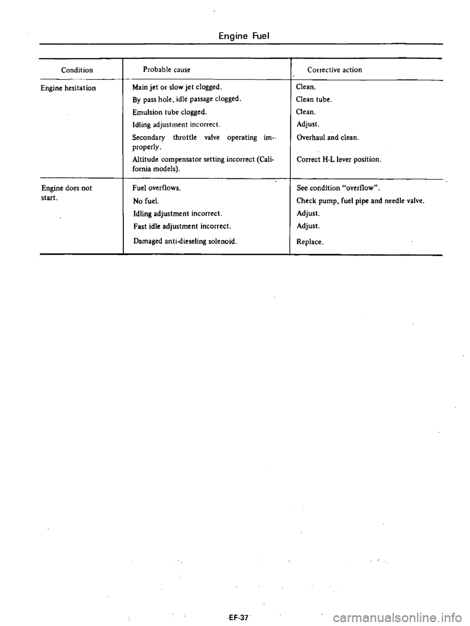
Condition
Engine
hesitation
Engine
does
not
start
Engine
Fuel
Probable
cause
Main
jet
or
slow
jet
clogged
By
pass
hole
idle
passage
dogged
Emulsion
tube
dogged
Idling
adjustment
incorrect
Secondary
throttle
valve
operating
im
properly
Altitude
compensator
setting
incorrect
Cali
fornia
models
Fuel
overflows
No
fuel
Idling
adjustment
incorrect
Fast
idle
adjustment
incorrect
Damaged
anti
dieseling
solenoid
EF
37
Corrective
action
Clean
Clean
tube
Clean
Adjust
Overhaul
and
clean
Correct
H
L
lever
position
See
condition
overflow
Check
pump
fuel
pipe
and
needle
valve
Adjust
Adjust
Replace
Page 144 of 537
Air
control
valve
CalifornIa
models
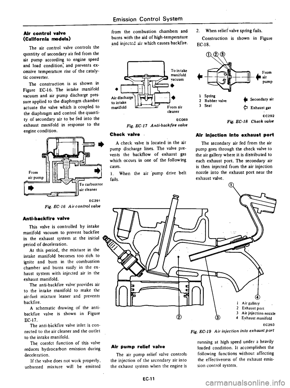
The
air
control
valve
con
troIs
the
quantity
of
secondary
air
fed
from
the
air
pump
according
to
engine
speed
and
load
condition
and
prevents
ex
cessive
temperature
rise
of
the
cataly
tic
converter
The
construction
is
as
shown
in
Figure
EC
16
The
intake
manifold
vacuum
and
air
pump
discharge
pres
sure
applied
to
the
diaphragm
chamber
actuate
the
valve
which
is
coupled
to
the
diaphragm
and
control
the
quanti
ty
of
secondary
air
to
be
fed
into
the
exhaust
manifold
in
response
to
the
engine
condition
c
From
air
pump
To
carburetor
air
cleaner
lr
J
EC291
Fig
EC
16
Air
control
valve
Anti
backfire
valve
This
valve
is
con
trolled
by
intake
manifold
vacuum
to
prevent
backfire
in
the
exhaust
system
at
the
ini
tial
period
of
deceleration
At
this
period
the
mixture
in
the
intake
manifold
becomes
too
rich
to
ignite
and
burn
in
the
combustion
chamber
and
burns
easily
in
the
ex
haust
system
with
injected
air
in
the
exhaust
manifold
The
anti
backfire
valve
provides
air
to
the
intake
manifold
to
make
the
air
fuel
mixture
leaner
and
prevents
backfire
A
schematic
drawing
of
the
anti
backfire
valve
is
shown
in
Figure
EC
17
The
anti
backfire
valve
inlet
is
con
nected
to
the
air
cleaner
and
the
outlet
to
the
intake
manifold
Th
correct
function
of
It
jS
valve
reduces
hydrocarbon
emission
during
aeceleration
If
the
valve
does
not
work
properly
unburned
mixture
will
be
emitted
Emission
Control
System
from
the
combustion
chambers
and
burns
with
the
aid
of
high
temperature
and
injected
air
which
causes
backfire
I
Tointake
c
manifold
vacuum
I
L
AirdisChaJ1le
I
to
mtake
manifold
From
air
cleaner
ECQ69
Fig
EC
11
Anti
back
ir
valve
Check
valve
A
check
valve
is
located
in
the
air
pump
discharge
lines
The
valve
pre
ven
ts
the
backflow
of
exhaust
gas
which
occurs
in
one
of
the
following
cases
1
When
the
air
pump
drive
belt
fails
2
When
relief
valve
spring
fails
Construction
is
shown
in
Figure
EC
18
F
rom
m
pump
1
Spring
2
Rubber
valve
3
Seat
Secondary
air
Exhaust
gas
EC292
Fig
EC
1B
Check
valve
AIr
InJaction
Into
axhaust
port
The
secondary
air
fed
from
the
air
pump
goes
through
the
check
valve
to
the
air
gallery
where
it
is
distributed
to
each
exhaust
port
The
secondary
air
is
then
injected
from
the
air
injection
nozzle
into
the
exhaust
port
near
the
exhaust
valve
n
L
y
r
V
Air
pump
relief
valve
The
air
pump
relief
valve
controls
the
injection
of
the
secondary
air
into
the
exhaust
system
when
the
engine
is
EG
11
3
I
Air
gallery
2
Exhaust
port
3
Air
jnjection
nozzle
4
Exhaust
manifold
EC293
Fig
EC
19
Air
injection
into
exhaust
port
running
at
high
speed
under
a
heavily
loaded
condition
It
accomplishes
the
following
functions
without
affecting
the
effectiveness
of
the
exhaust
emis
sion
control
system
Page 145 of 537
Minimizes
exhaust
gas
tempera
lure
rise
2
Minimizes
horsepower
losses
re
suiting
from
air
injection
into
the
exhaust
system
3
Protects
pump
from
excessive
back
pressure
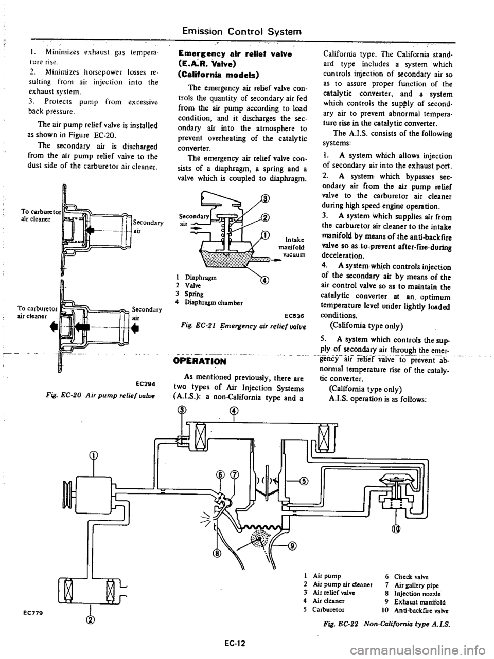
The
air
pump
relief
valve
is
installed
as
shown
in
Figure
EC
20
The
secondary
air
is
discharged
from
the
air
pump
relief
valve
to
the
dust
side
of
the
carburetor
air
cleaner
To
carburetor
air
cleaner
Secondary
air
To
carburetor
air
cleaner
J
erCOndary
r
r
EC294
Fig
EC
20
Air
pump
relief
valve
Emission
Control
System
Emargency
air
retial
valve
E
A
R
Valve
California
models
The
emergency
air
relief
valve
con
trols
the
quantity
of
secondary
air
fed
from
the
air
pump
according
to
load
condition
and
it
discharges
the
see
ondary
air
into
the
atmosphere
to
prevent
overheating
of
the
catalytic
converter
The
emergency
air
relief
valve
con
sists
of
a
diaphragm
a
spring
and
a
valve
which
is
coupled
to
diaphragm
1
Diaphragm
2
Val
3
Spring
4
Diaphragm
chamber
EC536
Fig
EC
21
mergency
air
relief
valve
OPERATION
As
mentioned
previously
there
are
two
types
of
Air
Injection
Systems
A
I
S
a
non
California
type
and
a
California
type
The
California
stand
ard
type
includes
a
system
which
controls
injection
of
secondary
air
so
as
to
assure
proper
function
of
the
catalytic
converter
and
a
system
which
controls
the
supply
of
second
ary
air
to
prevent
abnormal
tempera
tUfe
rise
in
the
catalytic
converter
The
A
I
S
consists
of
the
following
systems
L
A
system
which
allows
injection
of
secondary
air
into
the
exhaust
port
2
A
system
which
bypasses
sec
ondary
air
from
the
air
pump
relief
valve
to
the
carburetor
air
cleaner
during
high
speed
engine
operation
3
A
system
which
supplies
air
from
the
carburetor
air
cleaner
to
the
intake
manifold
by
means
of
the
anti
backfire
valve
so
as
to
prevent
after
fire
during
deceleration
4
A
system
which
controls
injection
of
the
secondary
air
by
means
of
the
air
control
valve
so
as
to
maintain
the
catalytic
converter
at
an
optimum
temperature
level
under
lightly
loaded
condi
tions
Califomia
type
only
5
A
system
which
controls
the
sup
ply
of
secondary
air
through
the
emer
gency
air
relief
vilve
io
pfevent
ab
normal
temperature
rise
of
the
cataly
tic
converter
California
type
only
A
I
S
operation
is
as
follows
I
I
t
1
r
9
I
Air
pump
6
Check
valve
I
0
L
2
Air
pump
air
deaner
7
Air
gallery
pipe
3
Air
relief
valve
8
Injection
non
e
r
4
Air
cleaner
9
Exhaust
manifold
5
Carburetor
10
Anti
backflIe
valve
EC179
Fig
EC
22
Non
California
type
A
I
S
EC
12
Page 155 of 537
j
EC231
Thermal
vacuum
valva
o
o
m
Emission
Control
System
0
o
o
o
l
l
@
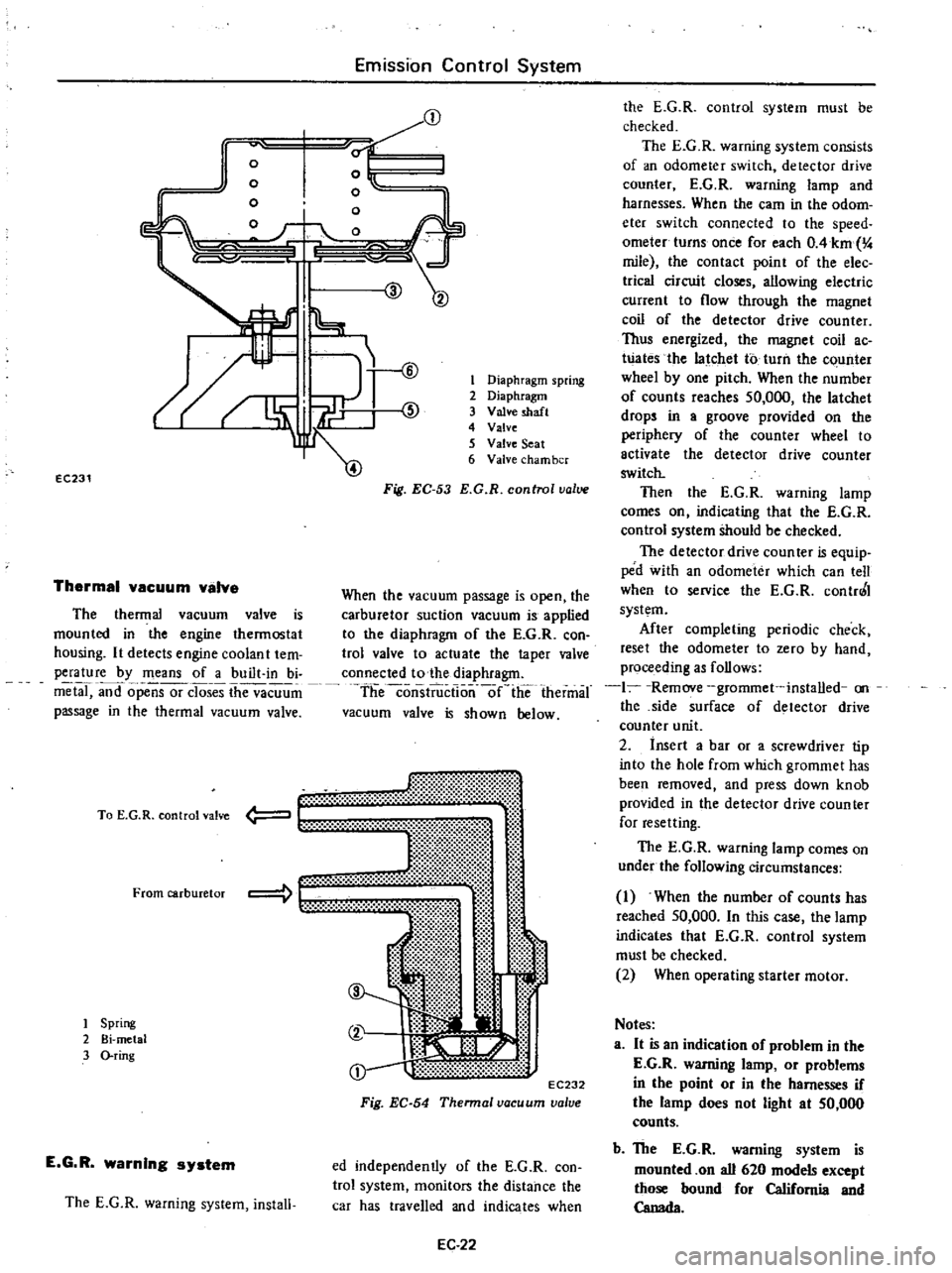
The
thermal
vacuum
valve
is
mounted
in
the
engine
thermostat
housing
It
detects
engine
coolan
t
tem
perature
by
means
of
a
built
in
bi
metal
and
opensor
closes
the
vacuum
passage
in
the
thermal
vacuum
valve
mt
li
t
00
t
EC232
Fig
EC
54
Thennal
vacuum
valve
To
E
G
R
control
valve
From
carburetor
1
Spring
2
Bi
metal
3
O
ring
E
G
R
warning
system
The
E
G
R
warning
system
install
1
Diaphragm
spring
2
Diaphragm
3
Valve
shaft
4
Valve
5
Valve
Seat
6
Valve
cham
ber
Fig
EC
53
E
G
R
control
value
When
the
vacuum
passage
is
open
the
carburetor
suction
vacuum
is
applied
to
the
diaphragm
of
the
E
G
R
con
trol
valve
to
actuate
the
taper
valve
connected
to
the
diaphragm
theconsiiiictlo
nlie
thermal
vacuum
valve
is
shown
below
ed
independently
of
the
E
G
R
con
trol
system
monitors
the
distance
the
car
has
travelled
and
indicates
when
EC
22
the
E
G
R
control
system
must
be
checked
The
E
G
R
warning
system
consists
of
an
odometer
switch
detector
drive
counter
E
G
R
warning
lamp
and
harnesses
When
the
earn
in
the
odom
eter
switch
connected
to
the
speed
ometer
turns
once
for
each
OAkm
4
mile
the
contact
point
of
the
elec
trica
circuit
closes
allowing
electric
current
to
flow
through
the
magnet
coil
of
the
detector
drive
counter
Thus
energized
the
magnet
coil
ac
Wates
the
latchet
to
turn
the
c
unter
wheel
by
one
pitch
When
the
number
of
counts
reaches
50
000
the
latchet
drops
in
a
groove
provided
on
the
periphery
of
the
counter
wheel
to
activate
the
detector
drive
counter
switch
Then
the
E
G
R
warning
lamp
comes
on
indicating
that
the
E
G
R
control
system
Should
be
checked
The
detector
drive
coun
teT
is
equip
ped
with
an
odometer
which
can
tell
when
to
service
the
E
G
R
contr0
I
system
After
completing
periodic
check
reset
the
odometer
to
zero
by
hand
proceeding
as
follows
1
Remove
grommet
installed
on
the
side
surface
of
detector
drive
counter
unit
2
insert
a
bar
or
a
screwdriver
tip
into
the
hole
from
which
grommet
has
been
removed
and
press
down
knob
provided
in
the
detector
drive
counter
for
resetting
The
E
G
R
warning
lamp
comes
on
under
the
following
circumstances
1
When
the
number
of
counts
has
reached
50
000
In
this
case
the
lamp
indicates
that
E
G
R
control
system
must
be
checked
2
When
operating
starter
motor
Notes
a
It
is
an
indication
of
problem
in
the
E
G
R
warning
lamp
or
problems
in
the
point
or
in
the
harnesses
if
the
lamp
does
not
light
at
50
000
counts
b
The
E
G
R
warning
system
is
mounted
on
all
620
models
except
those
bound
for
California
and
Canada
Page 158 of 537
Ignition
Switch
Position
START
Detector
Drive
Counter
E
G
R
Warning
Lamp
ON
b
After
completing
inspection
of
E
G
R
control
system
be
sure
to
reset
odometer
of
detector
drive
counter
to
zero
c
This
item
applies
to
all
620
models
except
those
bound
for
California
and
Canada
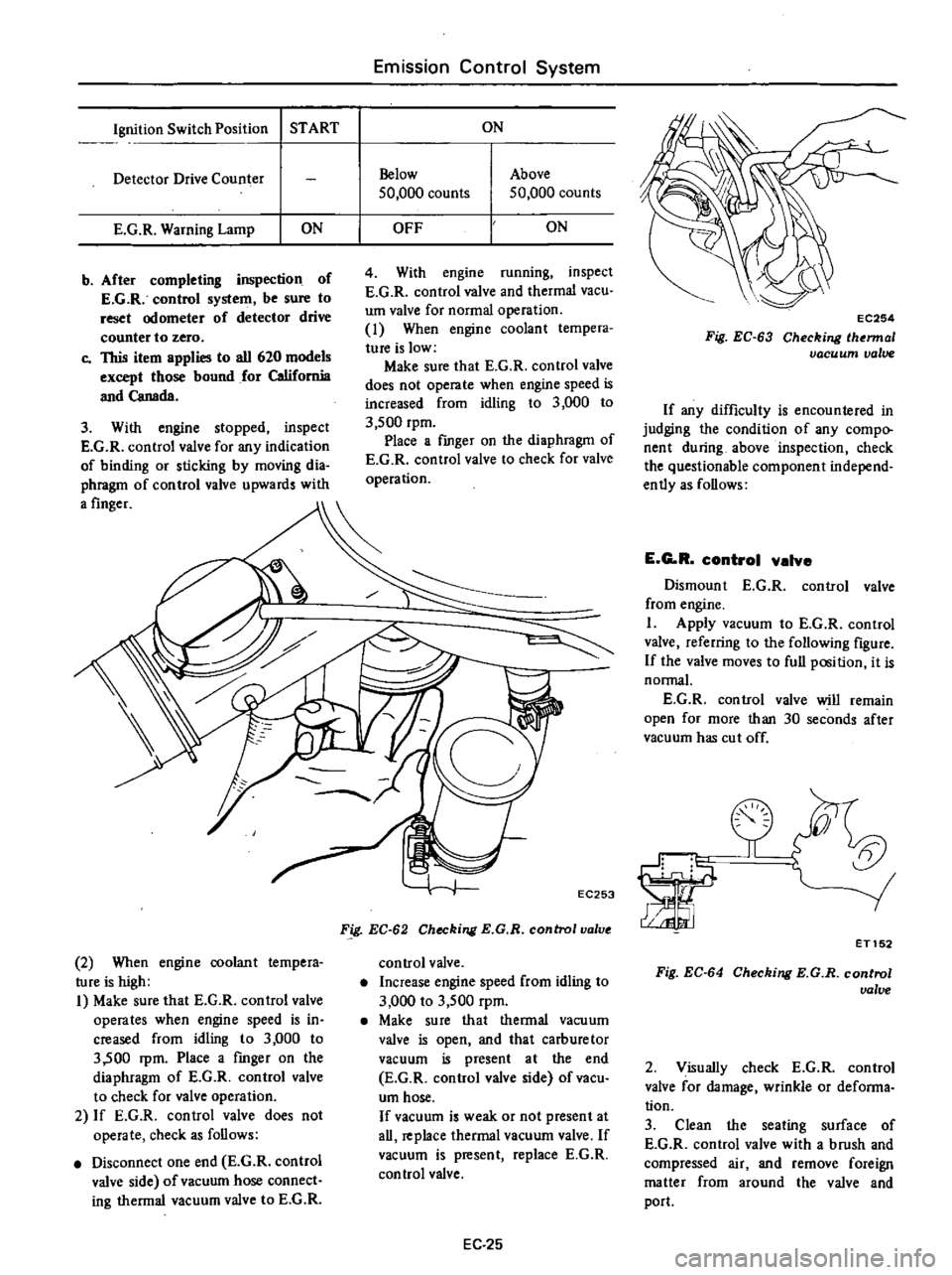
3
With
engine
stopped
inspect
E
G
R
control
valve
for
any
indication
of
binding
or
sticking
by
moving
dia
phragm
of
control
valve
upwards
with
a
finger
2
When
engine
coolant
tempera
ture
is
high
I
Make
sure
that
E
G
R
control
valve
operates
when
engine
speed
is
in
creased
from
idling
to
3
000
to
3
500
rpm
Place
a
fmger
on
the
diaphragm
of
E
G
R
control
valve
to
check
for
valve
operation
2
If
E
G
R
control
valve
does
not
operate
check
as
follows
Disconnect
one
end
E
G
R
control
valve
side
of
vacuum
hose
connect
ing
thermal
vacuum
valve
to
E
G
R
Emission
Control
System
ON
Below
50
000
counts
Above
50
000
counts
OFF
ON
4
With
engine
running
inspect
E
G
R
control
valve
and
thermal
vacuo
um
valve
for
normal
operation
1
When
engine
coolant
tempera
ture
is
low
Make
sure
that
E
G
R
control
valve
does
not
operate
when
engine
speed
is
increased
from
idling
to
3
000
to
3
500
rpm
Place
a
fmger
on
the
diaphragm
of
E
G
R
control
valve
to
check
for
valve
operation
EC253
Fig
EC
62
Checking
E
G
R
control
valve
control
valve
Increase
engine
speed
from
idling
to
3
000
to
3
500
rpm
Make
su
re
that
thermal
vacu
um
valve
is
open
and
that
carburetor
vacuum
is
present
at
the
end
E
G
R
control
valve
side
of
vacu
um
hose
If
vacuum
is
weak
or
not
present
at
all
replace
thermal
vacuum
valve
If
vacuum
is
present
replace
E
G
R
control
valve
EC
25
EC254
Fig
EC
63
Checking
lhermal
vacuum
valve
If
any
difficulty
is
encountered
in
judging
the
condition
of
any
compo
nent
during
above
inspection
check
the
questionable
component
independ
ently
as
follows
E
G
R
control
valve
Dismount
E
G
R
control
valve
from
engine
I
Apply
vacuum
to
E
G
R
control
valve
referring
to
the
following
figure
If
the
valve
moves
to
full
position
it
is
normal
E
G
R
control
valve
will
remain
open
for
more
than
30
seconds
after
vacuum
has
cut
off
la
ET152
Fig
EC
64
Checking
E
G
R
control
ualue
2
Visually
check
E
G
R
control
valve
for
damage
wrinkle
or
defonna
tion
3
Clean
the
seating
surface
of
E
G
R
control
valve
with
a
brush
and
compressed
air
and
remove
foreign
matter
from
around
the
valve
and
port
Page 193 of 537
NON
CALIFORNIA
MODELS
Engine
Electrical
System
IGNITION
CIRCUIT
CONTENTS
EE
26
CALIFORNIA
MODELS
EE
2B
NON
CALIFORNIA
MODELS
The
ignition
circuit
consists
of
the
ignition
switch
coil
distributor
wiring
spark
plugs
and
battery
The
circuit
is
equipped
with
a
resistor
During
cranking
electrical
current
bypasses
the
resistor
thereby
connecting
the
ignition
coil
directly
to
battery
This
provides
full
battery
voltage
available
at
coil
and
keeps
ignition
voltage
as
high
as
possible
The
low
voltage
current
is
supplied
by
the
battery
or
alternator
and
flows
through
the
primary
circuit
It
consists
of
the
ignition
switch
resistor
primary
winding
of
the
ignition
coil
distributor
contact
points
condenser
and
all
connecting
low
tension
wiring
The
high
voltage
current
is
pro
duced
by
the
ignition
coil
and
flows
through
the
secondary
circuit
result
ing
in
high
voltage
spark
between
the
electrodes
of
the
spark
plugs
in
engine
cylinders
This
circuit
contains
the
0
cl
Battery
Ignition
coil
secondary
winding
of
the
ignition
coil
high
tension
wiring
distributor
rotor
and
cap
When
the
ignition
switch
is
turned
on
and
the
distributor
contact
points
are
closed
the
primary
current
flows
through
the
primary
winding
of
the
coil
and
through
the
contact
points
to
ground
When
the
contact
points
are
opened
by
the
revolving
distributor
earn
the
magnetic
field
built
up
in
the
primary
winding
of
the
coil
moves
through
the
secondary
winding
of
the
coil
inducing
high
voltage
The
high
voltage
is
produced
every
time
the
contact
points
open
The
high
voltage
current
flows
through
the
high
tension
wire
to
the
distributor
cap
Then
the
rotor
distributes
the
current
to
one
of
the
spark
plug
terminals
in
the
distributor
Re5istor
To
starter
Secondary
winding
Cap
Breaker
point
f
Distributor
EE
26
cap
Then
the
spark
obtains
while
the
high
voltage
current
jumps
the
gap
between
the
insulated
electrode
and
the
ground
side
electrode
of
the
spark
plug
This
process
is
repeated
for
each
power
stroke
of
the
engine
The
distributor
contact
point
and
spark
plugs
should
be
inspected
clean
ed
and
regapped
at
tune
up
They
should
also
be
replaced
periodically
as
specified
in
the
Maintenance
Sched
ule
In
addition
apply
grease
NLGl
consistency
No
I
containing
MoS2
or
equivalent
to
distributor
shaft
and
grease
MIL
G
l0924B
containing
MoS2
or
equivalent
to
cam
as
reo
quired
The
remainder
of
the
ignition
component
parts
should
be
inspected
for
only
their
operation
tightness
of
electrical
terminals
and
wiring
con
dition
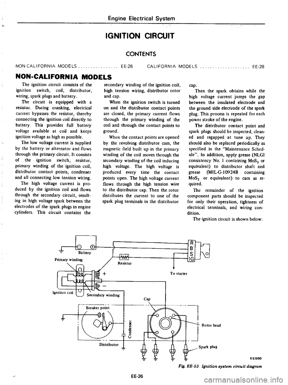
The
ignition
circuit
is
shown
below
IR
IB
I
is
21
J
g
Rotor
head
EE060
Fig
EE
53
Ignition
ydem
circuit
diagram
Page 195 of 537
Primary
winding
1
Ignition
coo
I
Secondary
winding
CALIFORNIA
MODELS
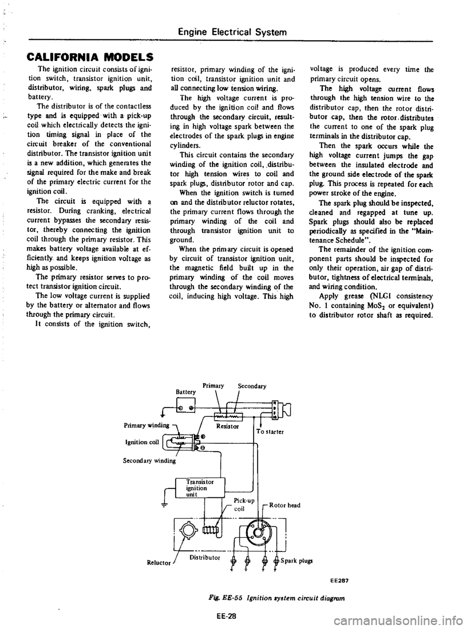
The
ignition
circuit
consists
of
igni
tion
switch
transistor
ignition
unit
distributor
wiring
spark
plugs
and
battery
The
distributor
is
of
the
contactless
type
and
is
equipped
with
a
pick
up
coil
which
electrically
detects
the
igni
tion
timing
signal
in
place
of
the
circuit
breaker
of
the
conventional
distributor
The
transistor
ignition
unit
is
a
new
addition
which
generates
the
signal
required
for
the
make
and
break
of
the
primary
electric
current
for
the
ignition
coil
The
circuit
is
equipped
with
a
resistor
During
cranking
electrical
current
bypasses
the
secondary
resis
tor
thereby
connecting
the
ignition
coil
through
the
primary
resistor
This
makes
battery
voltage
available
at
ef
ficiently
and
keeps
ignition
voltage
as
high
as
possible
The
primary
resistor
selVeS
to
pro
tect
transistor
ignition
circuit
The
low
voltage
current
is
supplied
by
the
battery
or
alternator
and
flows
through
the
primary
circuit
It
consists
of
the
ignition
switch
Engine
Electrical
System
resistor
primary
winding
of
the
igni
tion
coil
transistor
ignition
unit
and
all
connecting
low
tension
wiring
The
high
voltage
current
is
pro
duced
by
the
ignition
coil
and
flows
through
the
secondary
circuit
result
ing
in
high
voltage
spark
between
the
electrodes
of
the
spark
plugs
in
engine
cylinders
This
circuit
contains
the
secondary
winding
of
the
ignition
coil
distribu
tor
high
tension
wires
to
coil
and
spark
plugs
distributor
rotor
and
cap
When
the
ignition
switch
is
turned
on
and
the
distributor
reluctor
rotates
the
primary
current
flows
through
the
primary
winding
of
the
coil
and
through
transistor
ignition
unit
to
ground
When
the
prim
ary
circuit
is
opened
by
circuit
of
transistor
ignition
unit
the
magnetic
field
built
up
in
the
primary
winding
of
the
coil
moves
through
the
secondary
winding
of
the
coil
inducing
high
voltage
This
high
Battery
Primary
Secondary
I
Resistor
To
starter
r
Transis
tor
ignition
unit
I
I
Pick
up
rcoil
r
Rotor
head
nl
J
R5
U1f
1
Retuctor
r
oi
l
f
S
park
plugs
voltage
is
produced
every
time
the
primary
circuit
opens
The
high
voltage
current
flows
through
the
high
tension
wire
to
the
distributor
cap
then
the
rotor
distri
butor
cap
then
the
rotor
distributes
the
current
to
one
of
the
spark
plug
terminals
in
the
distributor
cap
Then
the
spark
occurs
while
the
high
voltage
current
jumps
the
gap
between
the
insulated
electrode
and
the
ground
side
electrode
of
the
spark
plug
This
process
is
repeated
for
each
power
stroke
of
the
engine
The
spark
plug
should
be
inspected
cleaned
and
regapped
at
tune
up
Spark
plugs
should
also
be
replaced
periodically
as
specified
in
the
Main
tenance
Schedule
The
remainder
of
the
ignition
com
ponent
parts
should
be
inspected
for
only
their
operation
air
gap
of
distri
butor
tightness
of
electrical
terminals
and
wiring
condition
Apply
grease
NLGI
consistency
No
I
containing
MoS
or
equivalent
to
distributor
rotor
shaft
as
required
EE287
EE
28
Fig
EE
55
Ignition
8Y3tem
circuit
diagram
Page 200 of 537
Engine
Electrical
System
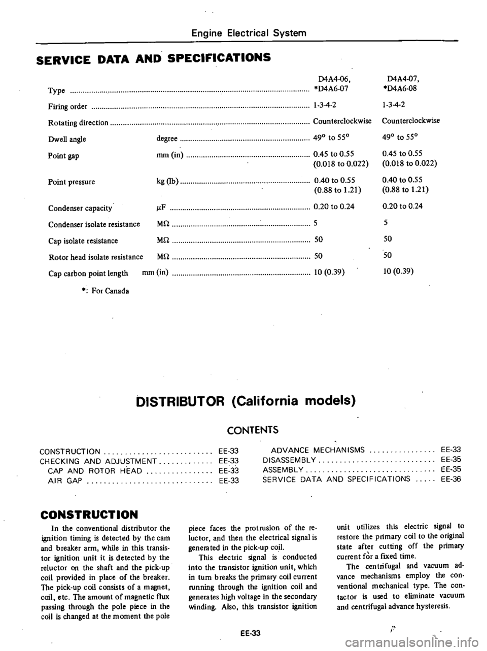
SERVICE
DATA
AND
SPECIFICATIONS
D4A4
06
D4A4
07
Type
D4A6
07
D4A6
08
Firing
order
1
3
4
2
13
4
2
Rotating
direction
Counterclockwise
Counterclockwise
Owen
angle
degree
490
to
550
490
to
550
Point
gap
mm
in
0
45
to
0
55
0
45
to
0
55
0
018
to
0
022
0
018
to
0
022
Point
pressure
kg
lb
0
40
to
0
55
0
40
to
0
55
0
88
to
1
21
0
88
to
1
21
Condenser
capacity
JlF
0
20
to
0
24
0
20
to
0
24
Condenser
isolate
resistance
Mrl
5
5
Cap
isolate
resistance
Mrl
50
50
Rotor
head
isolate
resistance
Mrl
50
50
Cap
carbon
point
length
mm
in
10
0
39
10
0
39
For
Canada
DISTRIBUTOR
California
models
CONSTRUCTION
CHECKING
AND
ADJUSTMENT
CAP
AND
ROTOR
HEAD
AIR
GAP
CONSTRUCTION
In
the
conventional
distributor
the
ignition
liming
is
detected
by
the
cam
and
breaker
arm
while
in
this
transis
tor
ignition
unit
it
is
detected
by
the
reluctor
on
the
shaft
and
the
pick
up
coil
provided
in
place
of
the
breaker
The
pick
up
coil
consists
of
a
magnet
coil
etc
The
amount
of
magnetic
flux
passing
through
the
pole
piece
in
the
coil
is
changed
at
the
moment
the
pole
CONTENTS
EE
33
EE
33
EE
33
EE
33
ADVANCE
MECHANISMS
DISASSEMBLY
ASSEMBLY
SERVICE
DATA
AND
SPECIFICATIONS
EE
33
EE
35
EE
35
EE
36
piece
faces
the
protrusion
of
the
re
luctor
and
then
the
electrical
signal
is
genera
ted
in
the
pick
up
coil
This
electric
signal
is
conducted
into
the
transistor
ignition
unit
which
in
turn
breaks
tI
e
primary
coil
current
running
through
the
ignition
coil
and
generates
high
voltage
in
the
secondary
winding
Also
this
transistor
ignition
EE
33
unit
utilizes
this
electric
signal
to
restore
the
primary
coil
to
the
original
state
after
cutting
off
the
primary
current
for
a
fIXed
time
The
centrifugal
and
vacuum
ad
vance
mechanisms
employ
the
con
ventional
mechanical
type
The
con
tactor
is
used
to
eliminate
vacuum
and
centrifugal
advance
hysteresis
I
Page 213 of 537
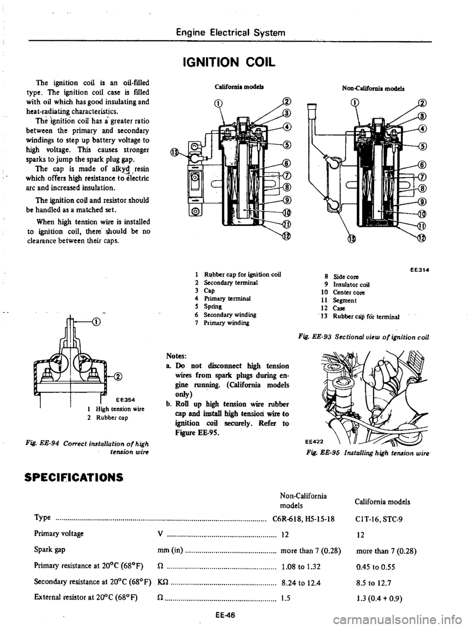
The
ignition
coil
is
an
oil
f1l1ed
type
The
ignition
coil
case
is
filled
with
oil
which
has
good
insulating
and
heat
radiating
characteristics
The
ignition
coil
has
a
greater
ratio
between
the
primary
and
secondary
windings
to
step
up
battery
voltage
t
high
voltage
This
causes
stronger
sparks
to
jump
the
spark
plug
gap
The
cap
is
made
of
alkyd
resin
which
offers
high
resistance
to
lectric
arc
and
increased
insulation
The
ignition
coil
and
resistor
should
be
handled
as
a
matched
set
When
high
tension
wire
is
installed
to
ignition
coil
there
should
be
no
clearance
between
their
caps
I
EE354
1
High
tension
wire
2
Rubber
cap
Fig
EE
94
Correcl
installation
of
high
t
Mjon
win
SPECIFICATIONS
Type
Primary
voltage
Spark
gap
Primary
resistance
at
200C
680F
Secondary
resistance
at
200C
680
F
KSl
External
resistor
at20
C
680F
n
Engine
Electrical
System
IGNITION
COIL
California
models
f
ID
@
J
C
ID
I
1W
1
R
bber
cap
for
ignition
coil
2
Secondary
terminal
3
Cap
4
Primary
terminal
5
Spring
6
Secondary
winding
7
Primary
winding
Notes
a
Do
not
disconnect
high
tension
wires
from
spark
plugs
during
en
gine
mnning
California
models
only
b
RoD
up
high
tension
wire
mbber
cap
and
instaD
high
tension
wire
to
ignition
coil
securely
Refer
to
Figure
EE
9S
Non
califomia
models
EE314
8
Side
core
9
Insulator
coil
10
Center
core
11
Segment
12
Case
13
Rubber
cap
Cor
terminal
Fig
EE
93
Sectional
view
of
ignition
coil
Fig
EE
95
Installing
high
tension
wire
Non
California
California
models
models
C6R
618
HS
15
18
CIT
16
STC
9
12
12
more
than
7
0
28
more
than
7
0
28
1
08
to
1
32
0
45
to
0
55
8
24
to
12
4
8
5
to
12
7
1
5
1
3
0
4
0
9
V
mm
in
n
EE
46
Page 262 of 537
The
model
3N7l
B
automatic
trans
mission
is
a
fully
automatic
unit
con
sisting
primarily
of
3
element
hydrau
lic
torque
converter
and
two
planetary
gear
sets
Two
multiple
disc
clutches
a
multiple
disc
brake
a
band
brake
and
a
one
way
sprag
clutch
provide
the
friction
elements
required
to
obtain
the
desir
d
function
of
lhe
two
plane
tary
gear
sets
The
two
planetary
gear
sets
give
three
forward
ratios
and
one
reverse
Changing
of
the
gear
ratios
is
fully
automatic
in
relation
to
vehicle
speed
and
engine
torque
input
V
chide
speed
and
engine
manifold
vacuum
signals
are
constantly
fed
to
the
transmission
to
provide
the
proper
gear
ralio
for
maximum
efficiency
and
performance
at
all
throttle
openings
The
model
3N71
B
has
six
selector
1
9sition
LP
R
N
D
2
1
I
Park
position
positively
locks
the
output
shaft
to
the
transmission
case
by
means
of
a
locking
pawl
to
prevent
the
vehicle
from
rolling
in
either
direction
This
position
should
be
selected
whenever
the
driver
leaves
Ihe
vehicle
Thc
engine
may
be
slarted
in
Park
position
R
Reverse
range
enables
the
vehicle
to
be
operated
in
a
reverse
direction
N
Neutral
position
enables
the
engine
to
be
started
and
run
without
driving
the
vehicle
0
Drive
range
is
used
for
all
normal
driving
conditions
Drive
range
has
three
gear
ratios
from
the
starting
ratio
to
direct
drive
Automatic
Transmission
DESCRIPTION
2
2
range
provides
performance
for
driving
on
slippery
surfaces
2
range
can
also
be
used
for
engine
braking
2
range
can
be
selected
at
any
vehicle
speed
and
prevents
the
trans
mission
from
shifting
out
of
second
gear
I
I
range
can
be
selected
at
any
vehicle
speed
and
the
transmission
will
shift
to
second
gear
and
remain
in
second
until
v
hicle
speed
is
reduced
10
approximately
40
to
50
kmfh
25
to
30
MPH
I
range
position
prevents
the
transmission
from
shifting
out
of
low
gear
This
is
particularly
beneficial
for
maintaining
maximum
engin
braking
when
continuous
low
gear
operation
is
desirable
The
torque
converter
assembly
is
of
welded
construction
and
can
nOlbe
disassembled
for
service
FLUID
RECOMMENDATION
Use
automatic
transmission
fluid
having
DEXRON
identifications
only
in
the
3N71
B
automatic
transmis
sion
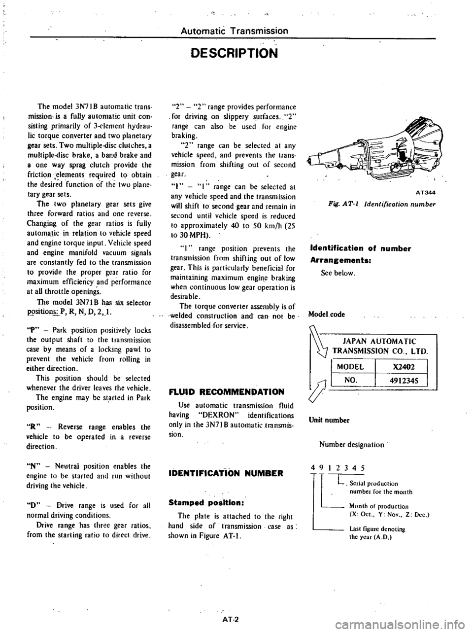
IDENTIFICATioN
NUMBER
Stamped
position
The
plate
is
attached
to
the
right
hand
side
of
transmission
case
as
shown
io
Figure
AT
I
AT
2
AT344
Fig
AT
I
Identification
number
Identification
of
number
Arrangements
See
below
Model
code
JAPAN
AUTOMATIC
0J
TRANSMISSION
CO
LTD
I
MODEL
X2402
I
J
I
NO
4912345
I
Unit
number
Number
designation
4
9
I
234
5
L
Serial
production
number
for
the
month
Month
of
production
X
Oct
Y
Nov
Z
Dec
last
figure
denoting
the
year
A
D