clutch DATSUN PICK-UP 1977 Owner's Manual
[x] Cancel search | Manufacturer: DATSUN, Model Year: 1977, Model line: PICK-UP, Model: DATSUN PICK-UP 1977Pages: 537, PDF Size: 35.48 MB
Page 227 of 537
Stroke
30
mm
Jt
i
I
1
18
in
Sj
1
i
J
o
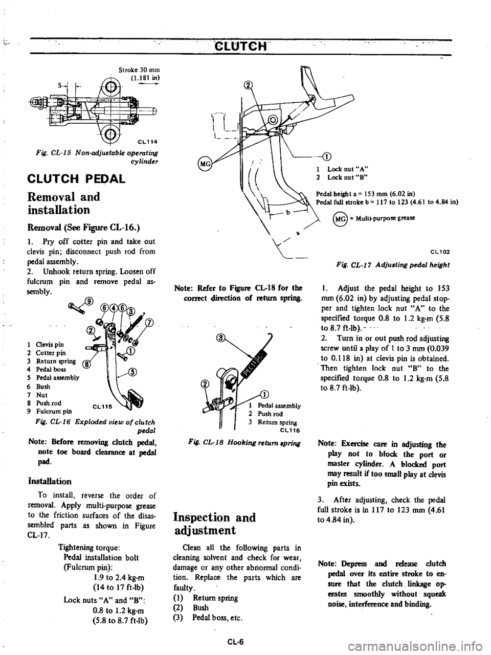
Fig
CL
15
Non
adj
table
operating
cylinder
CLUTCH
PEDAL
Removal
and
installation
Removal
See
Figure
CL
16
1
Pry
off
cotter
pin
and
take
out
clevis
pin
disconnect
push
rod
from
pedal
assembly
2
Unhook
return
spring
Loosen
off
fulcrum
pin
and
remove
pedal
as
sembly
CfJ
W5
6
3
ch
fD
ij
ll
i
A
1
aevis
pin
2
Cotter
pin
3
Return
spring
4
Pedal
boss
S
Pedal
assembly
6
Bush
7
Nut
8
Push
rod
9
Fulcrum
pin
Fig
CL
16
Exploded
view
of
clutch
pedal
Note
Before
removing
clutch
pedal
note
toe
board
clearance
at
pedal
pad
Installation
To
install
reverse
the
order
of
removal
Apply
multi
purpose
grease
to
the
friction
surfaces
of
the
disas
sembled
parts
as
shown
in
Figure
CL
17
Tightening
torque
Pedal
installation
bolt
Fulcrum
pin
1
9
to
2
4
kg
m
14
to
17
ft
Ib
Lock
nuts
A
and
B
0
8
to
1
2
kg
m
5
8
to
8
7
ft
lb
CLtJTCH
Note
Refer
to
Figure
Clot8
for
the
correct
direction
of
return
spring
1
Pedal
assembly
2
Push
rod
3
Return
spring
eL116
Fig
CL
1B
Hooking
return
pring
Inspection
and
adjustment
Clean
all
the
following
parts
in
cleaning
solvent
and
check
for
wear
damage
or
any
other
abnormal
condi
tion
Replace
the
parts
which
are
faulty
1
Return
spring
2
Bush
3
Pedal
boss
etc
CL
6
1
Lock
nut
A
2
Lock
nut
8
Pedal
beiBht
a
53
mm
6
02
in
Pedal
full
stroke
b
117
10
23
4
6
104
84
in
@
Multi
purpose
grease
CL102
Fig
CL
17
Adju
ting
pedal
height
1
Adjust
the
pedal
height
to
153
mm
6
02
in
by
adjusting
pedal
stop
per
and
tighten
lock
nut
A
to
the
specified
torque
0
8
to
1
2
kg
m
5
8
to
8
7
ft
lb
2
Turn
in
or
out
push
rod
adjusting
screw
until
a
play
of
I
to
3
mm
0
039
to
0
118
in
at
clevis
pin
is
obtained
Then
tighten
lock
nut
B
to
the
specified
torque
0
8
to
1
2
kg
m
5
8
to
8
7ft
Ib
Note
Exercise
care
in
adjusting
the
play
not
to
block
the
port
or
master
cylinder
A
blocked
port
may
result
if
too
small
play
at
clevis
pin
exists
3
After
adjusting
check
the
pedal
full
stroke
is
in
117
to
123
mm
4
61
to
4
84
in
Note
Depress
and
release
clutch
pedal
over
its
entire
stroke
to
en
sure
that
the
clutch
linkage
op
erates
smoothly
without
squeak
noise
interference
and
binding
Page 228 of 537
CLUTCH
CYLINDER
MASTER
Removal
and
installation
Removal
I
Remove
clcvis
pin
at
push
rod
2
Disconnect
clutch
tube
from
master
cylinder
and
drain
clutch
fluid
3
Remove
bolts
securing
master
Disassembly
and
assembly
CLUTCH
cylinder
to
the
vehicle
and
dismount
master
cylinder
Note
Remove
dust
cover
from
master
cylinder
body
on
the
side
of
driv
er
s
seat
Installation
To
install
reverse
the
order
of
removal
Closely
observe
the
following
instructions
1
Adjust
pedal
height
by
changing
pedal
stopper
length
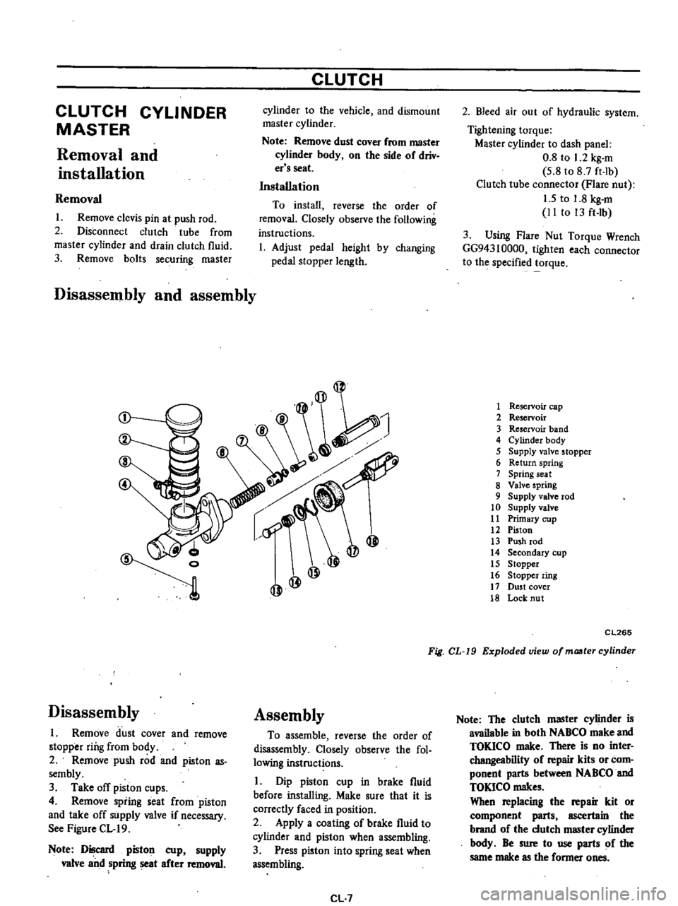
Disassembly
1
Remove
dust
cover
and
remove
stopper
ring
from
body
2
Remove
push
rod
and
piston
as
sembly
3
Take
off
piston
cups
4
Remove
spiing
seat
from
piston
and
take
off
supply
valve
if
necessary
See
Figure
CL
19
Note
Discard
piston
cup
supply
valve
and
spring
seat
after
removal
Assembly
To
assemble
reverse
the
order
of
disassembly
Closely
observe
the
fol
lowing
instructions
I
Dip
piston
cup
in
brake
fluid
before
installing
Make
sure
that
it
is
correctly
faced
in
position
2
Apply
a
coating
of
brake
fluid
to
cylinder
and
piston
when
assembling
3
Press
piston
into
spring
seat
when
assembling
CL
7
2
Bleed
air
out
of
hydraulic
system
Tightening
torque
Master
cylinder
to
dash
panel
0
8
to
1
2
kg
m
5
8
to
8
7
ft
lb
Clutch
tube
connector
Flare
nut
1
5
to
1
8
kg
m
II
to
13
ft
lb
3
Using
Flare
Nut
Torque
Wrench
GG94310000
tighten
each
connector
to
the
specified
torque
1
Reservoir
cap
2
Reservoir
3
Reservoir
band
4
Cylinder
body
5
Supply
valve
stopper
6
Return
spring
7
Spring
seat
8
Valve
spring
9
Supply
valve
rod
10
Supply
valve
11
Primary
cup
12
Piston
13
Push
rod
14
Secondary
cup
15
Stopper
16
Stopper
ring
17
DU5t
cover
18
Lock
nut
CL265
Fig
CL
19
Exploded
view
of
maater
cylinder
Note
The
clutch
master
cylinder
is
available
in
both
NABCO
make
and
TOKICO
make
There
is
no
inter
changeability
of
repair
kits
or
com
ponent
parts
between
NABCO
and
TOKlCO
makes
When
replacing
the
repair
kit
or
component
parts
ascertain
the
brand
of
the
clutch
IIIBSter
cylinder
body
Be
sure
to
use
parts
of
the
same
make
as
the
former
ones
Page 229 of 537
Inspection
Note
To
clean
or
wash
all
parts
of
master
cylinder
operating
cylinder
and
piping
clean
brake
fluid
must
be
used
Never
use
minera10ils
llUch
as
gasoline
and
kerosene
It
will
ruin
the
rubber
parts
of
the
hydrau
lic
system
I
Check
cylinder
and
piston
for
uneven
wear
or
damage
and
if
neces
sary
replace
2
If
the
clearance
between
cylinder
and
piston
is
more
than
0
15
mm
0
0059
in
replace
cylinder
3
Renew
piston
cup
when
dis
assembled
It
must
also
be
replaced
when
wear
or
deformation
due
to
fatigue
or
damage
is
found
4
Damaged
dust
cover
oil
reservoir
or
cap
should
be
replaced
Return
spring
and
valve
spring
must
also
be
replaced
when
they
are
broken
or
weak
5
Replace
clutch
hose
and
tube
if
any
abnormal
sign
of
damage
or
de
fro
ti
n
is
found
OPERATING
CYLINDER
Removal
and
installation
Removal
1
Detach
clutch
hose
from
operat
ing
cylinder
2
Remove
two
bolts
securing
op
erating
cylinder
to
clutch
housing
Installation
Install
in
the
reverse
order
of
re
moval
Observe
the
following
instructions
Bleed
air
thoroughly
from
clutch
hydraulic
system
2
Do
not
install
return
spring
or
clutch
will
not
be
disengaged
properly
Tightening
torque
Operating
cylinder
securing
bolt
2
5
to
3
5
kg
m
18
to
25
ft
lb
Bleeder
screw
0
7
to
0
9
kg
m
5
1
to
6
5
ft
Ib
Clutch
hose
connector
1
7
to
2
0
kg
m
12
to
14
ft
b
CLUTCH
Disassembly
and
assembly
Disassembly
1
Remove
push
rod
with
dust
cover
2
Remove
piston
assembly
and
pis
ton
spring
3
Remove
bleeder
screw
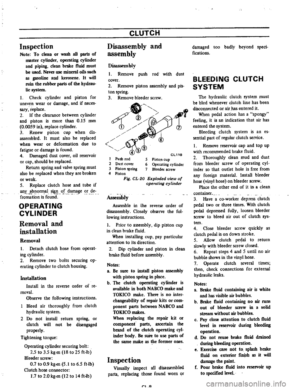
1
6
Cl11B
5
Piston
cup
6
Operating
cylinder
7
Bleeder
screw
1
Push
rod
2
Dust
cover
3
Piston
spring
4
Piston
Fig
CL
20
Exploded
view
of
operating
cyUnder
Assembly
Assemble
in
the
reverse
order
of
disassembly
Closely
observe
the
fol
lowing
instructions
1
Prior
to
assembly
dip
piston
cup
in
clean
brake
fluid
When
installing
cup
pay
particular
attention
to
its
direction
2
Dip
cylinder
and
piston
in
clean
brake
fluid
before
assembly
Notes
a
Be
sure
to
install
piston
assembly
with
piston
spring
in
place
b
The
clutch
operating
cylinder
is
available
in
both
NABCO
make
and
TOKICO
make
There
is
no
inter
changeability
of
repair
kits
or
com
ponent
parts
between
NABCO
and
TOKICO
makes
When
replacing
the
repair
kit
or
component
parts
ascertain
the
brand
of
the
clutch
operating
cyl
inder
bndy
Be
sure
to
use
parts
of
the
same
make
as
the
former
ones
Inspection
Visually
inspect
all
disassembled
parts
replacing
those
found
worn
or
rl
Q
damaged
too
badly
beyond
speci
fications
BLEEDING
CLUTCH
SYSTEM
The
hydraulic
clutch
system
must
be
bled
whenever
clutch
line
has
been
disconnected
or
air
has
entered
it
When
pedal
action
has
a
spongy
feeling
it
is
an
indication
that
air
has
entered
the
system
Bleeding
clutch
system
is
an
es
sential
part
of
regular
clutch
service
I
Remove
reservoir
cap
and
top
up
with
recommended
brake
fluid
2
Thoroughly
clean
mud
and
dust
from
bleeder
screw
of
operating
cyl
inder
so
that
outlet
hole
is
free
from
any
foreign
rnaterial
Install
bleeder
hose
vinyl
hose
on
bleeder
screw
Place
the
other
end
of
it
in
a
clean
container
3
Have
a
co
worker
depress
clutch
pedal
two
or
three
times
With
clu
tch
pedal
depressed
fully
loosen
bleeder
screw
to
bleed
air
out
of
clutch
sys
tern
4
Close
bleeder
screw
quickly
as
clutch
pedal
is
on
down
stroke
5
Allow
clutch
pedal
to
return
slowly
with
bleeder
screw
closed
6
Repeat
steps
4
and
5
until
no
air
bubble
shows
in
the
vinyl
hose
7
Operate
clutch
several
times
then
check
connections
for
external
hydraulic
leaks
Notes
a
Brake
fluid
containing
air
is
white
and
has
visible
air
bubbles
b
Brake
fluid
containing
no
air
runs
out
of
bleeder
screw
in
a
solid
stream
without
air
bubble
c
Pay
close
attention
to
clutch
fluid
level
in
reservoir
during
bleeding
operation
d
Do
not
reuse
brake
fluid
drained
during
bleeding
operation
e
Exercise
care
not
to
splash
brake
fluid
on
exterior
fInish
as
it
will
damage
the
paint
f
Pour
brake
fluid
into
reservoir
up
to
specifIed
level
Page 230 of 537
CLUTCH
SERVICE
DATA
AND
SPECIFICATIONS
Clutch
cover
Clu
tch
cover
type
Diaphragm
spring
to
flywheel
distance
Unevenness
of
diaphragm
spring
toe
height
Full
load
Out
of
flatness
of
pressure
plate
Allowable
refacing
limit
of
pressure
plate
Clutch
disc
Facing
size
Outer
dia
x
inside
dia
x
thickness
Thickness
of
disc
assembly
Free
Compressed
Number
of
torsion
springs
Allowable
minimum
depth
of
rivet
head
from
surface
Allowable
facing
run
out
Allowable
free
play
of
spline
at
the
outer
edge
of
disc
Clutch
pedal
Pedal
height
Play
at
clevis
pin
Full
stroke
Clutch
master
cylinder
Dia
of
master
cylinder
Allowable
maximum
clearance
between
cylinder
and
piston
Clutch
operating
cylinder
Dia
of
operating
cylinder
Tightening
torque
Clutch
assembly
to
flywheel
securing
bolt
Pedal
installation
bolt
Fulcrum
pin
Pedal
stopper
lock
nut
Push
rod
lock
nut
Master
cylinder
to
dash
panel
securing
bolt
Clutch
tube
connector
Flare
nut
Clutch
hose
connector
Operating
cylinder
to
clutch
housing
securing
bolt
Bleeder
screw
mm
in
mm
in
kg
Qb
mm
in
mm
in
Diaphragm
C225S
33
to
35
1
23
to
1
38
less
than
0
5
0
020
400
882
0
1
0
004
1
0
0
040
mm
in
225
x
150
x
3
5
8
86
x
5
91
x
0
138
mm
in
mm
in
8
3
to
8
9
0
327
to
0
350
7
6
to
8
0
0
299
to
0
315
6
0
3
0
012
0
5
0
020
0
4
0
016
mm
in
mm
in
mm
in
mm
in
153
6
02
mm
in
I
to
3
0
039
to
0
118
mm
in
117
to
123
4
61
to
4
84
mm
in
15
87
5
8
mm
in
0
15
0
0059
mm
in
19
05
Yo
kg
m
ft
lb
1
5
to
2
2
lito
16
kg
m
ft
Ib
1
9
to
2
4
14
to
17
kg
m
ft
b
0
8
to
1
2
5
8
to
8
7
kg
m
ft
lb
0
8
to
1
2
5
8
to
8
7
kg
m
ft
Ib
0
8
to
1
2
5
8
to
8
7
kg
m
ft
lb
1
5
to
1
8
11
to
13
kg
m
ft
lb
1
7
to
2
0
12
to
14
kg
m
ft
lb
2
5
to
3
5
18
to
25
kg
m
ft
Ib
0
7
to
0
9
5
1
to
6
5
CL
9
Page 231 of 537
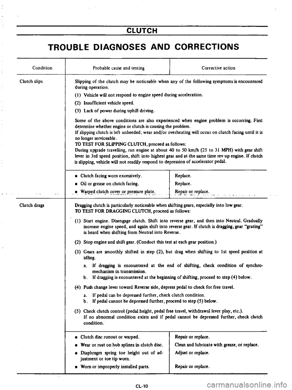
CLUTCH
TROUBLE
DIAGNOSES
AND
CORRECTIONS
Condition
Probable
cause
and
testing
Clutch
slips
Corrective
action
Slipping
of
the
clutch
may
be
noticeable
when
any
of
the
following
symptoms
is
encountered
during
operation
I
Vehicle
will
not
respond
to
engine
speed
during
acceleration
2
Insufficient
vehicle
speed
3
Lack
of
power
during
uphill
driving
Some
of
the
above
conditions
are
also
experienced
when
engine
problem
is
oc
urring
First
de
tennine
whether
engine
or
clutch
is
causing
the
problem
If
slipping
clutch
is
left
unheeded
wear
and
or
overheating
will
occur
on
clutch
facing
until
it
is
no
longer
serviceable
TO
TEST
FOR
SLIPPING
CLlJfCH
proceed
as
follows
During
upgrade
travelling
run
engine
at
about
40
to
50
km
h
25
to
31
MPH
with
gear
shift
lever
in
3rd
speed
position
shift
into
highest
gear
and
at
the
same
time
rev
up
engine
If
clutch
is
slipping
vehicle
will
not
readily
respond
to
depression
of
accelerator
pedal
Clutch
facing
worn
excessively
Oil
or
grease
on
clutch
facing
W
r
d
clut
h
cov
r
pressure
plat
Replace
Replace
tpa
o
e
lace
Dragging
clutch
is
particularly
noticeable
when
shifting
gears
especially
into
low
gear
TO
TEST
FOR
DRAGGING
CLlJfCH
proceed
as
follows
I
Start
engine
Disengage
clutch
Shift
into
reverse
gear
and
then
into
Neutral
Gradually
increase
engine
speed
and
again
shift
into
reverse
gear
If
clutch
is
dragging
gear
grating
is
heard
when
shifting
from
Neutral
into
Reverse
Clutch
drags
2
Stop
engine
and
shift
gear
Conduct
this
test
at
each
gear
position
3
Gears
are
smoothly
shifted
in
step
2
but
drag
when
shifting
to
1st
speed
position
at
idling
a
If
dragging
is
encountered
at
the
end
of
shifting
check
condition
of
synchro
mechanism
in
transmission
b
If
dragging
is
encountered
at
the
beginning
of
shifting
proceed
to
step
4
below
4
Push
change
lever
toward
Reverse
side
depress
pedal
to
check
for
free
travel
a
If
pedal
can
be
depressed
further
check
clutch
condition
b
If
pedal
cannot
be
depressed
further
proceed
to
step
5
below
5
Check
clutch
control
pedal
height
pedal
free
travel
withdrawal
lever
play
etc
If
no
abnonnal
condition
exists
and
if
pedal
cannot
be
depressed
further
check
clutch
condition
Clutch
disc
runout
or
warped
Wear
or
rust
on
hub
splines
in
clutch
disc
Diaphragm
spring
toe
height
out
of
ad
justment
or
toe
tip
worn
Worn
or
improperly
installed
parts
CL10
Repair
or
replace
Clean
and
lubricate
with
grease
or
replace
Adjust
or
replace
Repair
or
replace
Page 232 of 537
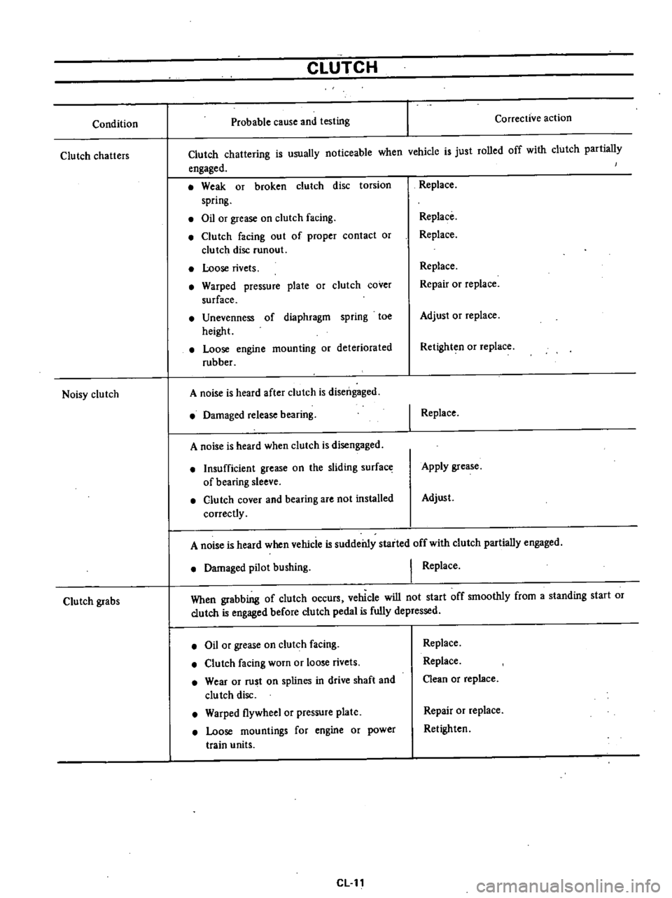
Condition
Clutch
chatters
Noisy
clutch
Clutch
grabs
CLUTCH
Probable
cause
and
testing
Corrective
action
Clutch
chattering
is
usually
noticeable
when
vchicle
is
just
rolled
off
with
clutch
partially
engaged
Weak
or
broken
clutch
disc
torsion
spring
Oil
or
grease
on
clutch
facing
Clutch
facing
out
of
proper
contact
or
clutch
disc
runout
Loose
rivets
Warped
pressure
plate
or
clutch
cover
surface
Unevenness
of
diaphragm
spring
toe
height
Loose
engine
mounting
or
deteriorated
rubber
A
noise
is
heard
after
clutch
is
disengaged
Damaged
release
bearing
A
noise
is
heard
when
clutch
is
disengaged
Insufficient
grease
on
the
sliding
surface
of
bearing
sleeve
Clutch
cover
and
bearing
are
not
installed
correctly
Replace
Replace
Replace
Replace
Repair
or
replace
Adjust
or
replace
Retighten
or
replace
I
Replace
Apply
grease
Adjust
A
noise
is
heard
when
vehicle
is
suddei11y
staited
off
with
clutch
partially
engaged
Damaged
pilot
bushing
I
Replace
When
grabbing
of
clutch
occurs
vehicle
will
not
start
off
smoothly
from
a
standing
start
or
clutch
is
engaged
before
clutch
pedal
is
fully
depressed
Oil
or
grease
on
clutch
facing
Clutch
facing
worn
or
loose
rivets
Wear
or
rust
on
splines
in
drive
shaft
and
clu
tch
disc
Warped
flywheel
or
pressure
plate
Loose
mountings
for
engine
or
power
train
units
CLll
Replace
Replace
Clean
or
replace
Repair
or
replace
Retighten
Page 233 of 537

Cl
Ul
CFf
SPECIAL
SERVICE
TOOLS
Tool
number
For
Reference
No
Description
use
page
or
tool
name
on
Figure
No
Unit
mm
in
ST20050010
620
Fig
CL
12
Base
plate
00
B210
710
610
y
S30
2
ST20050051
Set
bolt
SE002
q
3
ST20050
100
Distance
@
piece
7
8
mm
0
31
in
@1
@J
SEOQ3
4
ST20050240
620
Fig
CL
13
Diaphragm
B210
adjusting
710
wrench
610
S30
SE032
5
KV30100200
Clutch
aligning
bar
This
tool
is
used
to
conduct
disc
centeril
g
by
inserting
the
tool
into
pilot
bush
in
flywheel
when
installing
clutch
assembly
to
flywheel
620
710
610
S30
Fig
CL
2
Fig
CL
3
SEaOl
6
STl6610001
Pilot
bushing
puller
Fig
CL
6
620
710
610
S30
SE191
CL
12
Page 234 of 537
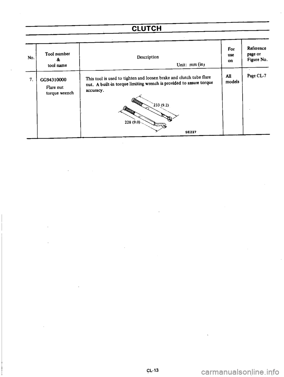
No
Tool
number
tool
name
7
GG94310000
Flare
nut
torque
wrench
CLUTCH
Description
Unit
mm
in
This
tool
is
used
to
tighten
and
loosen
brake
and
clutch
tube
flare
nut
A
built
in
torque
limiting
wrench
is
provided
to
assure
torque
accuracy
y
SE227
CL
13
For
use
on
All
models
Reference
page
or
Figure
No
Page
CL
7
Page 236 of 537
Manual
Transmission
4
SPEED
TRANSMISSION
TYPE
F4W71B
CONTENTS
DESCRIPTION
REMOVAL
DISASSEMBL
Y
TRANSMISSION
CASE
DISASSEMBLY
D
ISASSEMBL
Y
OF
GEAR
ASSEMBLY
REAR
EXTENSION
DISASSEMBLY
ADAPTER
PLATE
DISASSEMBLY
INSPECTION
TRANSMISSION
CASE
AND
REAR
EXTENSION
HOUSING
BEARING
GEARS
AND
SHAFTS
BAULK
RING
Oil
SEAL
ASSEMBL
Y
FRONT
COVER
ASSEMBLY
REAR
EXTENSION
ASSEMBLY
ADAPTER
PLATE
ASSEMBLY
GEAR
ASSEMBLY
TRANSMISSION
ASSEMBLY
INSTALLATION
MT
2
MT
4
MT
4
MT
4
MT
5
MT
B
MT
8
MT
8
MT
B
MT
8
MT
8
MT
9
MT
9
MT
9
MT
9
MT
9
MT
9
MT
9
MT13
MT14
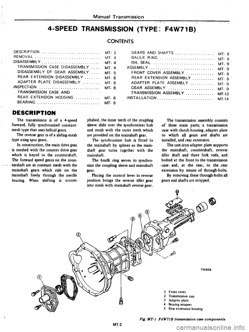
DESCRIPTION
pUshed
the
inner
teeth
of
the
coupling
sleeve
slide
over
the
synchronizer
hub
and
mesh
with
the
outer
teeth
which
are
provided
on
the
mainshaft
gear
The
synchronizer
hub
is
fitted
to
the
mainshaft
by
splines
so
the
main
shaft
gear
turns
together
with
the
mainshaft
The
baulk
ring
serves
to
synchro
nile
the
coupling
sleeve
and
mainshaft
gear
Placing
the
control
lever
in
reverse
position
brings
the
reverse
idler
gear
into
mesh
with
mainshaft
reverse
gear
The
transmission
is
of
a
4
speed
forward
fully
synchronized
constant
mesh
type
that
uses
helical
gears
The
reverse
gear
is
ofa
sliding
mesh
type
using
spur
gears
In
construction
the
main
drive
gear
is
meshed
with
the
counter
drive
gear
which
is
keyed
to
the
countershaft
The
forward
speed
gears
on
the
coun
tershaft
are
in
constant
mesh
with
the
mainshaft
gears
which
ride
on
the
mainshaft
freely
through
the
needle
bearing
When
shifting
is
accom
The
transmission
assembly
consists
of
three
main
parts
a
transmission
case
with
clutch
housing
adapter
plate
to
which
an
gears
and
shafts
are
installed
and
rear
extension
The
cast
iron
adapter
plate
supports
the
mainshaft
countershaft
reverse
idler
shaft
and
three
fork
rods
and
bolted
at
the
front
to
the
transmission
case
and
at
the
rear
to
the
rear
extension
by
means
of
through
bolts
By
removing
these
through
bolts
all
gears
and
shafts
are
stripped
e
TM
858
1
Front
cover
2
Transmission
case
3
Adapter
plate
4
Bearing
retainer
5
Rear
extension
hOUsing
Fig
MT
1
F4W71B
lrammiasion
case
compon
nt
MT
2
Page 238 of 537
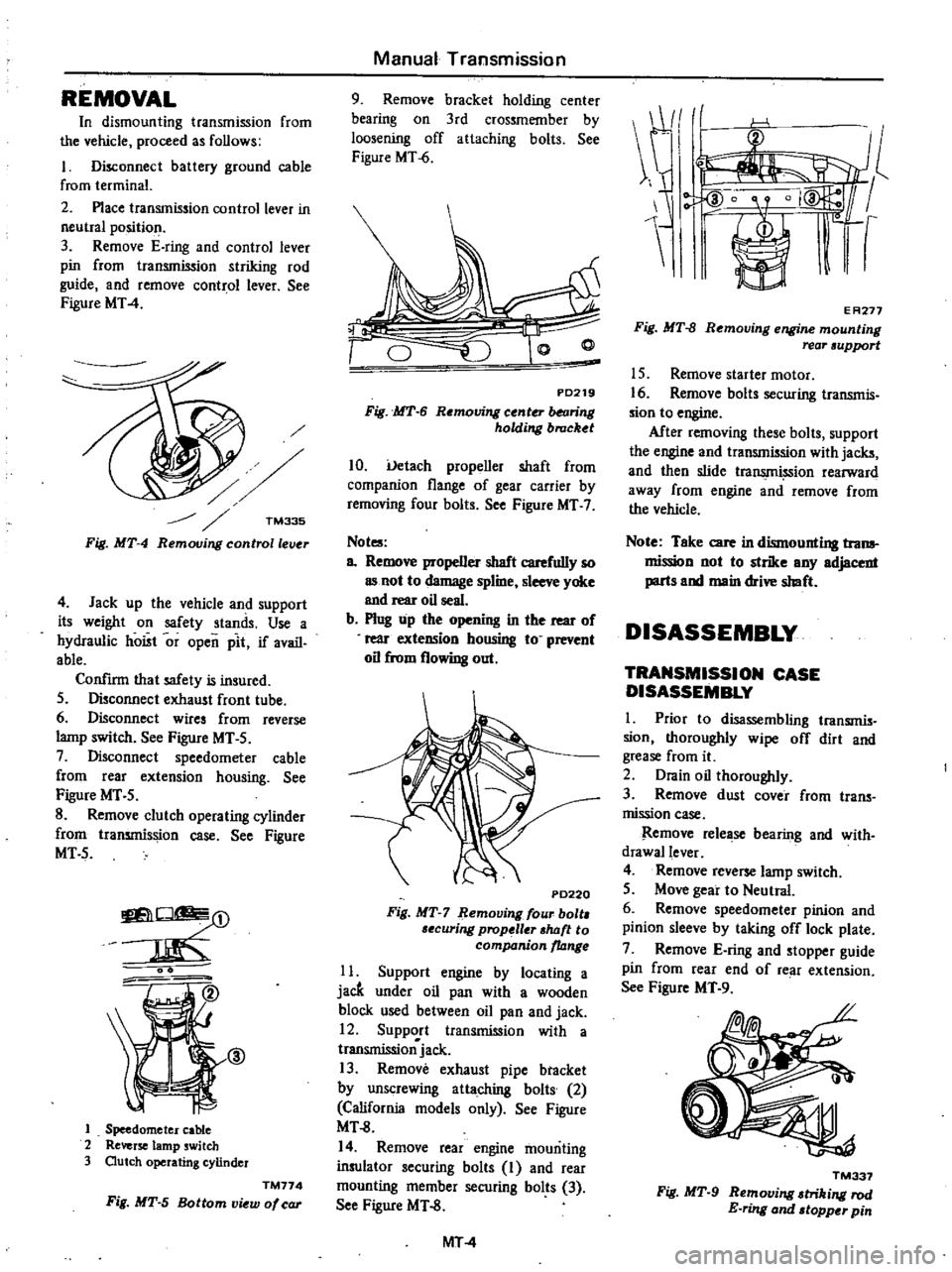
REMOVAL
In
dismounting
transmission
from
the
vehicle
proceed
as
follows
I
Disconnect
battery
ground
cable
from
terminal
2
Place
transmission
control
lever
in
neutIal
position
3
Remove
E
ring
and
control
lever
pin
from
transmission
striking
rod
guide
and
remove
control
lever
See
Figure
MT
4
TM335
Fig
MT
4
Remouing
controllelJ
r
4
Jack
up
the
vehicle
and
support
its
weight
on
safety
stands
Use
a
hydraulic
hoist
or
open
pit
if
avail
able
Confirm
that
safety
is
insured
5
Disconnect
exhaust
front
tube
6
Disconnect
wires
from
reverse
lamp
switch
See
Figure
MT
5
7
Disconnect
speedometer
cable
from
rear
extension
housing
See
Figure
MT
5
8
Remove
clutch
operating
cylinder
from
transmission
case
See
Figure
MT5
O
m
J
@
1
Speedometer
cable
2
Reverse
lamp
switch
3
Outch
operating
cylinder
TM774
Fig
MT
5
Bottom
view
of
car
Manual
Transmission
9
Remove
bracket
holding
center
bearing
on
3rd
crossmember
by
loosening
off
attaching
bolts
See
Figure
MT
6
PD219
Fig
MT
6
Removing
center
balring
holding
brucket
10
Uetach
propeller
shaft
from
companion
flange
of
gear
carrier
by
removing
four
bolts
See
Figure
MT
7
Not
a
Remove
propeller
shaft
carefully
so
as
not
to
damage
spline
sleeve
yoke
and
rear
oil
seal
b
Plug
up
the
opening
in
the
rear
of
rear
exteDSion
housing
to
prevent
oil
from
flowing
out
P0220
Fig
MT
7
Remouing
four
bolt
6ecuring
prop
ller
shtJft
to
companion
ltJnge
11
Support
engine
by
locating
a
jacft
under
oil
pan
with
a
wooden
block
used
between
oil
pan
and
jack
12
Support
transmission
with
a
transmissionjack
13
Remove
exhaust
pipe
btacket
by
unscrewing
attaching
bolts
2
California
models
only
See
Figure
MT
8
14
Remove
rear
engine
mounting
insulator
securing
bolts
I
and
rear
mounting
member
securing
bolts
3
See
Figure
MT
8
MT
4
E
A277
Fig
MT
8
Removing
engine
mounting
rear
support
15
Remove
starter
motor
16
Remove
bolt
securing
transmis
sion
to
engine
After
removing
these
bolts
support
the
engine
and
transmission
with
jacks
and
then
slide
tra
ion
rearward
away
from
engine
and
remove
from
the
vehicle
Note
Take
care
in
dismounting
trona
mission
not
to
strike
any
adjacent
parts
and
main
drive
shaft
DISASSEMBLY
TRANSMISSION
CASE
DISASSEMBLY
I
Prior
to
disassembling
transmis
sion
thoroughly
wipe
off
dirt
and
grease
from
it
2
Drain
oil
thoroughly
3
Remove
dust
cover
from
trans
mission
case
Remove
release
bearing
and
with
drawallever
4
Remove
reverse
lamp
switch
5
Move
gear
to
Neutral
6
Remove
speedometer
pinion
and
pinion
sleeve
by
taking
off
lock
plate
7
Remove
E
ring
and
stopper
guide
pin
from
rear
end
of
re
ll
extension
See
Figure
MT
9
TM337
Fig
MT
9
Removing
triking
rod
E
ring
and
topper
pin