differential DATSUN PICK-UP 1977 Owner's Manual
[x] Cancel search | Manufacturer: DATSUN, Model Year: 1977, Model line: PICK-UP, Model: DATSUN PICK-UP 1977Pages: 537, PDF Size: 35.48 MB
Page 344 of 537
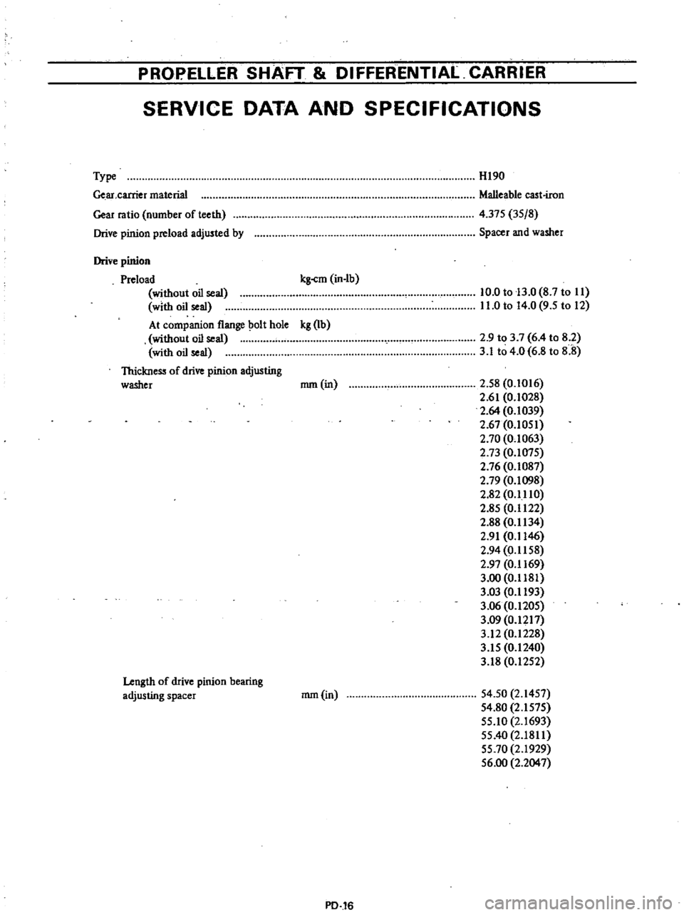
PROPELLER
SHAFT
DIFFERENTIAL
CARRIER
SERVICE
DATA
AND
SPECIFICATIONS
Type
Ge
ar
carrier
material
Gear
ratio
number
of
teeth
Drive
pinion
preload
adjusted
by
HI90
Malleable
cast
iron
4
375
3S
8
Spacer
and
washer
Drive
pinion
Preload
kg
cm
in
Ib
without
oil
seal
with
oil
seal
At
companion
flange
olt
hole
kg
Ib
without
oil
seal
with
oil
seal
Thickness
of
drive
pinion
adjusting
washer
nun
in
10
0
to
13
0
8
7
to
II
11
0
to
14
0
9
5
to
12
2
9
to
3
7
6
4
to
8
2
3
1
to
4
0
6
8
to
8
8
2
S8
0
1016
2
61
0
1028
2
64
0
1039
2
67
0
IOSI
2
70
0
1063
2
73
O
I07S
2
76
0
1087
2
79
0
1098
2
82
0
1110
2
8S
0
1122
2
88
0
1134
2
91
0
1146
2
94
0
1158
2
97
0
1169
3
00
0
1181
3
03
0
1193
3
06
0
120S
3
09
0
1217
3
12
0
1228
3
IS
0
1240
3
18
0
12S2
Length
of
drive
pinion
bearing
adjusting
spacer
nun
in
S4
50
2
14S7
54
80
2
IS7S
SS
IO
2
1693
SS
40
2
1811
SS
70
2
1929
S6
00
2
2047
PD
16
Page 345 of 537
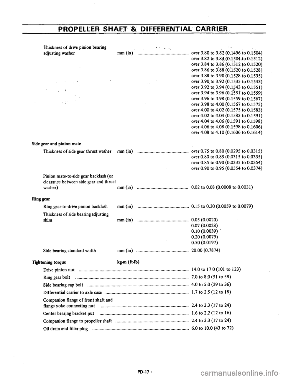
PROPELlER
SHAFT
DIFfERENTIALCARRI
ER
Thickness
of
drive
pinion
bearing
adjusting
washer
mm
in
over
3
80
to
3
82
0
1496
to
O
IS04
over
3
82
to
3
8
HO
IS04
to
OcISI2
over
3
84
to
3
86
0
ISI2
to
0
IS20
over
3
86
to
3
88
0
1520
to
0
IS28
over
3
88
to
3
90
0
IS28
to
0
IS3S
over
3
90
to
3
92
0
IS3S
to
0
1S43
over
3
92
to
3
94
0
1543
to
O
ISSI
over
3
94
to
3
96
0
I5si
to
0
ISS9
over
3
96
to
3
98
0
I5S9
to
0
IS67
over
3
98
to
4
00
0
1567
to
0
IS7S
over
4
00
to
4
02
0
157S
to
0
IS83
over
4
02
to
4
04
0
IS83
to
0
IS91
over
4
04
to
4
06
0
IS91
to
0
IS98
over
4
06
to
4
08
0
1598
to
0
1606
over
4
08
to
4
10
0
1606
to
0
1614
Side
gear
and
pinion
mate
Thickness
of
side
gear
thrust
washer
mOl
in
over
0
7S
to
0
80
0
029S
to
0
03IS
over
0
80
to
0
8S
0
03IS
to
0
033S
over
0
8S
to
0
90
0
0335
to
0
03S4
over
0
90
to
0
9S
0
03S4
to
0
0374
Pinion
mate
to
side
gear
backlash
or
clearance
between
side
gear
and
thrust
washer
mOl
in
0
02
to
0
08
0
0008
to
0
0031
Ring
gear
Ring
gear
to
drive
pinion
backlash
mm
in
Thickness
of
side
bearing
adjusting
shim
mOl
in
O
1S
to
0
20
0
00S9
to
0
0079
Side
bearing
standard
width
mm
in
O
OS
0
0020
0
07
0
0028
0
10
0
0039
0
20
0
0079
0
50
0
0197
20
00
0
7874
TIghtening
torque
Drive
pinion
nut
Ring
gear
bolt
Side
bearing
cap
bolt
Differential
carrier
to
axle
case
Companion
flange
of
front
shaft
and
flange
yoke
connecting
nut
Center
bearing
bracket
ut
Companion
flange
to
propeller
shaft
Oil
drain
and
filler
plug
kg
m
ft
Ib
14
0
to
17
0
101
to
123
7
0
to
8
0
SI
toS8
4
0
to
S
O
29
to
36
17
to
2
S
12
to
18
2
4
to
3
3
17
to
24
1
6
to
2
2
12
to
16
2
4
to
3
3
17
to
24
6
0
to
10
0
43
to
72
PD
l1
Page 346 of 537
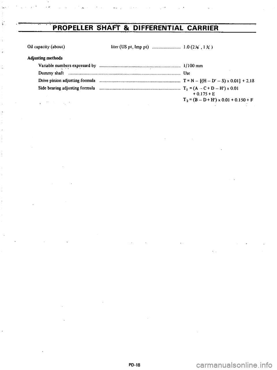
PROPELLER
SHAFT
DIFFERENTIAL
CARRIER
Oil
capacity
about
liter
US
pt
Imp
pt
1
0
2Ji
I
Y
Adjusting
methods
Variable
numbers
expressed
by
Dummy
shaft
Drive
pinion
adjusting
fonnula
Side
bearing
adjusting
fonnula
1
100
mOl
Use
T
N
H
0
S
x
0
01
2
18
TI
A
C
D
H
xO
OI
0
17S
E
T2
B
0
H
x
0
01
0
150
F
PD
18
Page 347 of 537
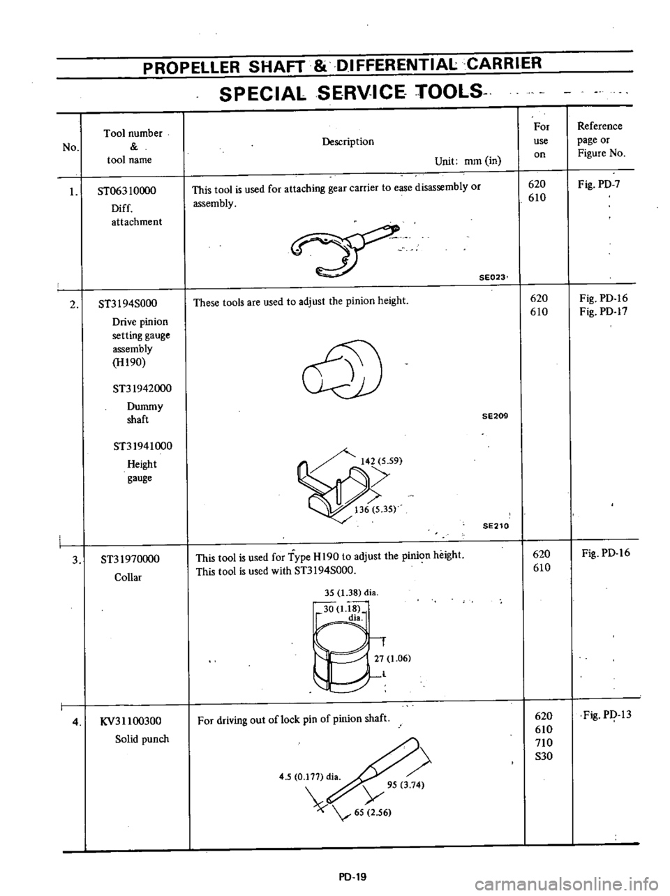
PROPELLER
SHAFT
8i
DIFFERENTIALCARRIER
SPECIAL
SERVICE
TOOlS
No
Tool
number
tool
name
I
ST063
10000
Diff
attachment
2
ST3I
94S000
Drive
pinion
setting
gauge
assembly
H190
ST31942000
Dummy
shaft
ST31941000
Height
gauge
3
ST31970000
Collar
4
KV311
00300
Solid
punch
Description
Unit
mOl
in
This
tool
is
used
for
attaching
gear
carrier
to
ease
disassembly
or
assembly
SE023
These
tools
are
used
to
adjust
the
pinion
height
@
SE209
SE210
This
tool
is
used
for
Type
H
190
to
adjust
the
pinion
height
This
tool
is
used
with
ST3I
94S000
35
1
38
di
30
1
18
dia
1
27
1
06
l
For
driving
out
oflock
pin
of
pinion
shaft
4
5
0
177
di
Y
95
3
74
65
2
56
PD
19
For
use
on
620
610
620
610
620
610
620
610
710
S30
Reference
page
or
Figure
No
Fig
PD
7
Fig
PD
16
Fig
PD
17
Fig
PD
16
Fig
PI
13
Page 349 of 537
PROPELLER
SHAFT
DIFFERENTIAL
CARRIER
Toollltlltlbcr
For
Reference
No
Description
use
page
or
tuol
nallle
Unit
mOl
in
on
Figure
No
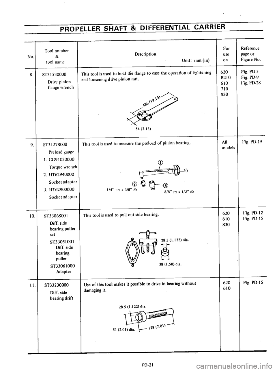
8
ST3
1530000
This
tool
is
used
to
hold
the
Ilange
to
case
the
operation
of
tightening
620
Fig
PD
5
Drive
pinion
and
lousening
drive
piniun
nut
8210
Fig
PD
Y
flange
wrench
610
Fig
PD
28
710
SJO
b
l
54
2
13
9
ST3127S000
This
toul
is
used
to
Ilwasure
the
preload
of
piniun
bearing
All
Fig
PD
19
Preload
gauge
models
GG91030000
Turque
wr
nch
CD
L
O
2
IIT62940000
lJ
Socket
adapter
ct
J
IIT62900000
1
4
II
J
x
3
8
3
8
L
UJ
1
2
r
Socket
adapter
10
ST3J06S001
This
tool
is
lIsed
to
Jut
oul
side
bearing
620
Fig
PD
12
Diff
side
610
Fig
PD
I
5
bearing
puller
SJO
set
ST3JOSIOOI
Diff
side
bearing
puller
STJ306
I
000
38
1
50
di
Adapter
II
ST33230000
Use
of
this
tool
makes
it
possible
to
drive
in
bearing
without
620
Fig
PD
IS
Diff
side
damaging
it
610
bearing
drift
1B
1
0ll
5t
2
0t
di
PD
21
Page 369 of 537
DESCRIPTION
The
rear
axle
assembly
is
of
the
semi
floating
type
in
which
the
vehicle
weight
is
carried
on
the
axle
shafts
through
bearings
enclosed
in
the
bear
ing
cages
on
outer
rear
axle
case
The
axle
case
is
a
pressed
steeJ
Banjo
type
housing
The
rear
axle
assembly
is
attached
to
the
frame
through
semi
elliptic
leaf
springs
and
telescopic
hydraulic
shock
absorbers
Rubber
bushings
at
either
end
of
the
leaf
springs
and
shock
absorbers
are
designed
to
absorb
vibra
tion
and
noise
The
rear
axle
shaft
splines
engage
the
differential
side
gears
with
a
float
ing
fit
The
outer
ends
are
supported
in
the
bearing
cages
by
tapered
roller
bearings
The
bearings
are
lubricated
by
wheel
bearing
grease
The
axle
shaft
oil
seals
are
located
outboard
and
inboard
of
the
bearing
The
bearings
are
se
cured
against
shoulders
on
the
shafts
by
press
fit
and
held
in
place
by
a
large
nuts
The
bearing
cages
hold
the
bearings
against
shoulders
on
the
axle
case
Whee
side
thrust
is
taken
at
the
wheel
bearings
through
the
thrust
block
so
an
axle
shaft
may
be
re
moved
simply
by
removing
the
bolts
holding
the
brake
disc
to
the
bearing
cage
and
the
rear
axle
case
REMOVAL
AND
INSTALLATION
REAR
AXLE
ASSEMBLY
It
is
not
necessary
to
remove
the
reaT
axle
assembly
for
any
normal
repairs
However
if
the
axle
case
is
dam
aged
the
rear
axle
assembly
may
be
removed
and
installed
using
the
fol
lowing
procedures
I
Raise
rear
of
vehicle
high
enough
to
permi
t
working
underneath
Place
a
jack
under
center
of
axle
case
so
it
just
starts
to
raise
rear
axle
assembly
Place
stands
solidly
under
frame
members
on
both
sides
Remove
rear
wheels
Rear
Axle
Rear
Suspension
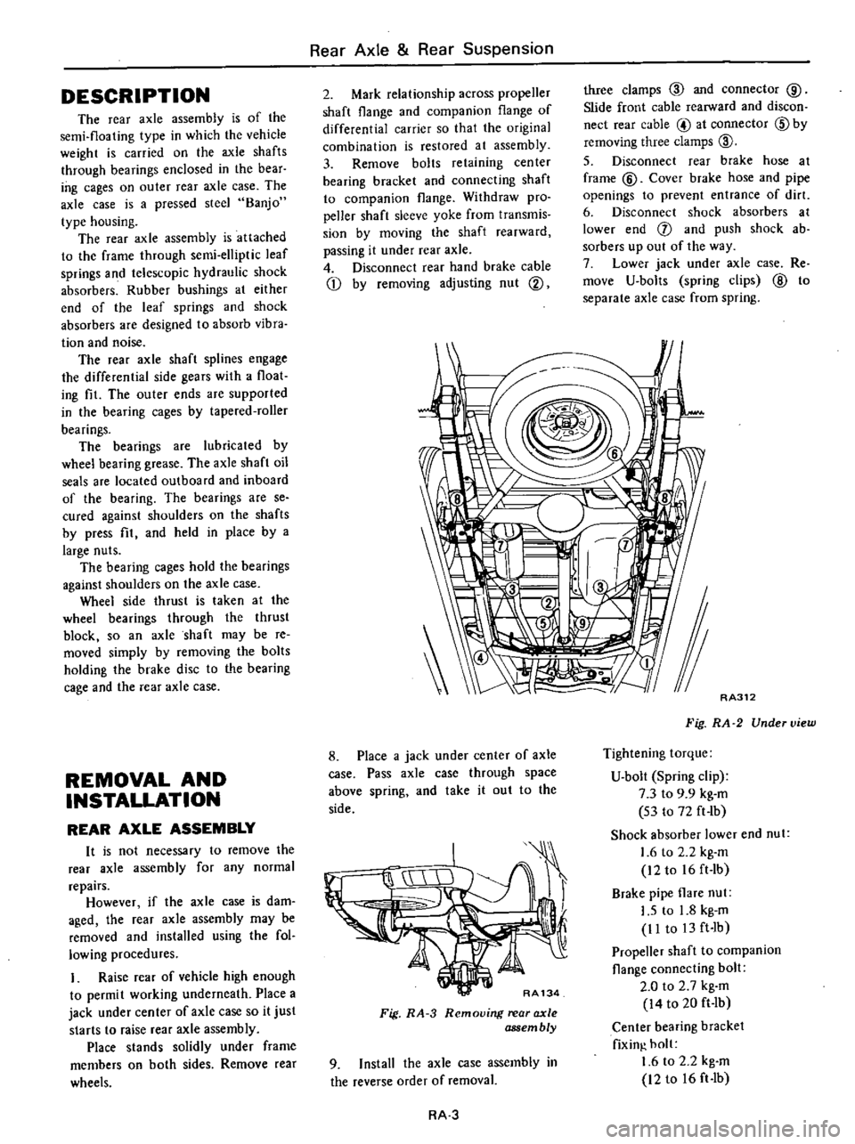
2
Mark
relationship
across
propeller
shaft
flange
and
companion
flange
of
differential
carrier
so
that
the
original
combination
is
restored
at
assembly
3
Remove
bolts
retaining
center
bearing
bracket
and
connecting
shaft
to
companion
flange
Withdraw
pro
peller
shaft
sleeve
yoke
from
transmis
sion
by
moving
the
shaft
rearward
passing
it
under
rear
axle
4
Disconnect
rear
hand
brake
cable
Q
by
removing
adjusting
nut
@
three
clamps
ID
and
connector
@
Slide
front
cable
rearward
and
discon
nect
rear
cable
@
at
connector
ID
by
removing
three
clamps
ID
5
Disconnect
rear
brake
hose
at
frame
@
Cover
brake
hose
and
pipe
openings
to
prevent
entrance
of
dirt
6
Disconnect
shock
absorbers
at
lower
end
f
and
push
shock
ab
sorbers
up
out
of
the
way
7
Lower
jack
under
axle
case
Re
move
U
bolts
spring
clips
@
to
separate
axle
case
from
spring
8
Place
a
jack
under
center
of
axle
case
Pass
axle
case
through
space
above
spring
and
take
it
out
to
the
side
RA134
Fig
RA
3
Removing
rear
axle
assembly
9
Install
the
axle
case
assembly
in
the
reverse
order
of
removal
RA
3
RA312
Fig
RA
2
Under
view
Tightening
torque
U
bolt
Spring
clip
7
3
to
9
9
kg
m
53
to
72
ft
lb
Shock
absorber
lower
end
nut
1
6
to
2
2
kg
m
12to
16ft
Ib
Brake
pipe
flare
nut
I
S
to
1
8
kg
m
II
to
13
ft
Ib
Propeller
shaft
to
companion
flange
connecting
bolt
2
0
to
2
7
kg
m
14
to
20
ft
Ib
Center
bearing
bracket
fixin
holt
1
6
to
2
2
kg
m
12
to
16
ft
Ib
Page 371 of 537
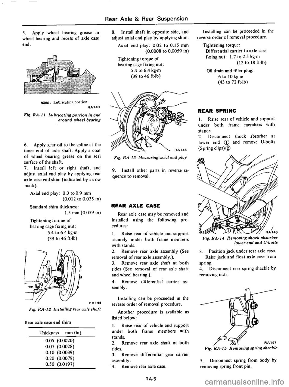
S
Apply
wheel
bearing
grease
in
wheel
bearing
and
recess
of
axle
case
end
Lubricating
portion
AA143
Fig
RA
l1
Lubricating
portion
in
and
around
wheel
bearing
6
Apply
gear
oil
to
the
spline
at
the
inner
end
of
axle
shaft
Apply
a
coal
of
wheel
bearing
grease
on
the
seal
surface
of
the
shaft
7
Install
left
or
right
shaft
and
adjust
axial
end
play
by
applying
rear
axle
case
end
shim
indicated
by
arrow
mark
Axial
end
play
0
3
to
0
9
mOl
0
012
to
0
035
in
Standard
shim
thickness
1
5
mm
0
059
in
Tightening
torque
of
bearing
cage
fIXing
nut
54
to
6
4
kg
m
39
to
46
ft
lb
w
AA144
Fig
RA
12
Installing
rear
axle
shaft
Rear
axle
case
end
shim
Thickness
mOl
in
O
OS
0
0020
0
07
0
0028
0
10
0
0039
0
20
0
0079
O
SO
0
0197
Rear
Axle
Rear
Suspension
8
Install
shaft
in
opposite
side
and
adjust
axial
end
play
by
applying
shim
Axial
end
play
0
02
to
O
IS
mOl
0
0008
to
0
0059
in
Tightening
torque
of
bearing
cage
fixing
nut
5
4
to
6
4
kg
m
39
to
46
ft
Ib
Fig
RA
13
Measuring
axial
end
play
9
Install
other
parts
in
reverse
se
quence
to
removal
REAR
AXLE
CASE
Rear
axle
case
may
be
removed
and
installed
using
the
following
pro
cedures
I
Raise
rear
of
vehicle
and
support
securely
under
both
frame
members
with
stands
2
Remove
rear
axle
assembly
See
removal
of
rear
axle
assembly
3
Remove
rear
axle
shaft
at
both
sides
See
removal
of
rear
axle
shaft
and
wheel
bearing
4
Remove
differentiai
carrier
as
sembly
Installing
can
be
proceeded
in
the
reverse
order
of
removal
procedure
Another
procedure
is
available
as
listed
below
I
Raise
rear
of
vehicle
and
support
under
both
frame
members
with
stands
2
Remove
ear
axle
shaft
at
both
sides
3
Remove
differential
gear
carrier
assembly
4
Remove
rear
axle
case
RA
5
Installing
can
be
proceeded
in
the
reverse
order
of
removal
procedure
Tightening
torque
Differential
carrier
to
axle
case
fixing
nut
I
7
to
2
5
kg
m
12
to
18
ft
Ib
Oil
drain
and
fIller
plug
6
to
10
kg
m
43
to
72
ft
lb
REAR
SPRING
1
Raise
rear
of
vehicle
and
support
under
both
frame
members
with
stands
2
Disconnect
shock
absorber
at
lower
end
CD
and
remove
U
bolts
Spring
clips
2
3
Position
jack
under
rear
axle
case
Raise
jack
and
float
axle
case
from
spring
4
Disconnect
rear
spring
shackle
by
removing
nuts
AA147
Fig
RA
15
Removing
spring
shackle
5
Disconnect
spring
from
body
by
removing
spring
front
pin
Page 374 of 537
Rear
Axle
Rear
Suspension
Spring
front
pin
Spring
shackle
Bearing
cage
fIXing
bolt
Wheel
bearing
lock
nut
Air
breather
Differential
gear
carrier
to
axle
case
nut
Propeller
shaft
flange
bolt
Drain
and
filler
plug
Bumper
rubber
fixing
bolt
Wheel
nut
kg
m
ft
lb
kg
m
ft
Ib
kg
en
ft
lb
kg
m
ft
Ib
kg
m
ft
Ib
kg
m
ft
Ib
kg
en
ft
Ib
kg
m
ft
Ib
kg
m
ft
Ib
kg
m
ft
lb
11
5
to
13
0
83
to
94
11
5
to
13
0
83
to
94
S
4
to
6
4
39
to
46
IS
to
20
108
to
l4S
0
7
to
0
9
S
I
to
6
S
17
to
2
7
12
to
20
2
0
to
2
7
14
to
20
6
to
10
43
to
72
1
6
to
2
2
12
to
16
8
to
9
S8
to
6S
TROUBLE
DIAGNOSES
AND
CORRECTIONS
When
rear
axle
and
suspension
is
suspected
of
being
noisy
it
is
advisable
to
make
a
thorough
test
to
determine
whether
the
noise
originates
in
the
tires
road
surface
exhaust
propeller
shaft
engine
transmission
universal
joint
wheel
bearings
or
suspension
Noise
which
originates
in
other
places
can
not
be
corrected
by
adjust
ment
or
replacement
of
parts
in
the
rear
axle
and
rear
suspension
In
case
of
oil
leak
first
check
if
there
is
any
damage
or
restriction
in
breather
Condition
Probable
cause
Noise
Loose
wheel
nuts
Loose
one
or
more
securing
bolts
Lack
of
lubricating
oil
or
grease
Faulty
shock
absorber
Incorrect
adjustment
of
rear
axle
shaft
end
play
Damaged
or
worn
wheel
bearing
Worn
spline
portion
of
rear
axle
shaft
Broken
leaf
spring
Loose
journal
connections
or
so
no
Wheel
and
tire
unbalance
Damaged
rubber
parts
such
as
leaf
spring
bush
shock
absorber
moun
ting
bush
Faulty
universal
joints
Instability
in
driving
Loose
wheel
nuts
Worn
shock
absorber
Worn
or
broken
leaf
spring
Oil
leakage
Damaged
or
restricted
air
breather
Damaged
oil
seal
in
rear
axle
case
or
differ
ential
carrier
Oil
leakage
from
between
the
differential
carrier
and
axle
case
RA
8
Corrective
action
Tighten
the
wheel
nuts
Tighten
the
bolts
to
the
specified
torque
Lubricate
as
required
Replace
the
shock
absorber
Adjust
the
rear
axle
shaft
end
play
Replace
wheel
bearing
Replace
if
necessary
Replace
leaf
spring
Tighten
to
the
given
torque
Balance
wheel
and
tire
Replace
the
required
parts
Adjust
or
replace
Tighten
to
the
given
torque
Replace
faulty
shock
absorber
Replace
leaf
spring
Clean
or
replace
air
breather
Replace
the
damaged
oil
seal
Tighten
to
the
specified
torque
or
replace
gasket
Page 522 of 537
DESCR
IPTIDN
COMPRESSOR
CLUTCH
REMOVAL
INSTAllATION
DISASSEMBLY
ASSEMBLY
INSPECTION
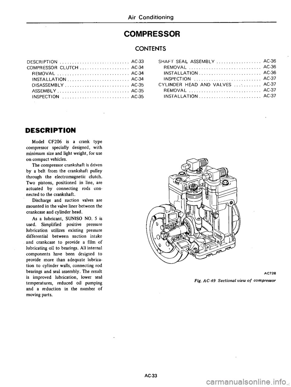
DESCRIPTION
Model
CF206
is
a
crank
type
compressor
specially
designed
with
minimum
size
and
light
weight
for
use
on
compact
vehicles
The
compressor
crankshaft
is
driven
by
a
belt
from
the
crankshaft
pulley
through
the
electromagnetic
clutch
Two
pistons
positioned
in
line
are
actuated
by
connecting
rods
coo
nected
to
the
crankshaft
Discharge
and
suction
valves
are
mounted
in
the
valve
liner
between
the
crankcase
and
cylinder
head
As
a
lubricant
SUNlSO
NO
5
is
used
Simplified
positive
pressure
lubrication
utilizes
existing
pressure
differential
between
suction
intake
and
crankcase
to
provide
a
film
of
lubricating
oil
to
bearings
All
internal
components
have
been
designed
to
provide
more
than
adequate
lubrica
tion
to
cylinder
walls
connecting
rod
bearings
and
seal
assembly
The
result
is
improved
lubrication
lower
seal
temperatures
reduced
oil
pumping
and
a
reduction
in
the
number
of
moving
parts
Air
Conditioning
COMPRESSOR
AC33
AC34
AC34
AC34
AC35
AC
35
AC35
CONTENTS
SHAFT
SEAL
ASSEMBLY
REMOVAL
INSTAllATION
INSPECTION
CYLINDER
HEAD
AND
VALVES
REMOVAL
INSTAllATION
AC36
AC36
AC36
AC37
AC37
AC37
AC37
AC728
Fig
AC
49
Sectional
view
of
compressor
AC33
Page 531 of 537
GENERAL
DESCRI
PTION
Special
Tools
play
very
important
role
in
the
maintenance
of
vehicles
These
are
essential
to
the
safe
accu
rate
and
speedy
servicing
The
working
times
listed
in
the
col
umn
under
FLAT
RATE
TIME
in
FLAT
RATE
SCHEDULE
are
com
puted
based
on
the
use
of
Special
Tools
The
identification
code
of
mainte
nance
tools
is
made
up
of
2
alpha
betical
letters
and
8
digital
figures
The
heading
two
letters
roughly
classify
tools
or
equipment
as
fol
lows
STOOOOOOOO
KVOOOOOOOO
Special
Tool
Special
Tool
Recently
established
Engine
Overhauling
Machine
General
Gauge
Hand
Tool
EMOOOOOOOO
GGOOOOOOOO
HTOOOOOOOO
HOW
TO
READ
SPECIAL
TOOL
LIST
APPLIED
VEHICLE
OR
UNIT
In
this
column
word
All
is
given
for
tools
applicable
to
all
vehicle
mod
els
and
unit
types
treated
in
this
manu
al
for
tools
applicable
only
to
particu
lar
models
or
units
those
vehicle
models
or
unit
types
are
indicated
NEWLY
ADDED
X
put
in
this
column
shows
newly
added
tools
Service
Equipment
SERVICE
EQUIPMENT
CLASS
Indicated
in
this
column
are
classi
fication
ftg1ll
es
in
accordance
with
Classification
of
Speciai
Tool
REMARKS
As
regards
special
tools
which
are
also
applicable
to
models
other
than
those
dealt
ith
U
this
m
inual
this
coluITUl
names
those
other
models
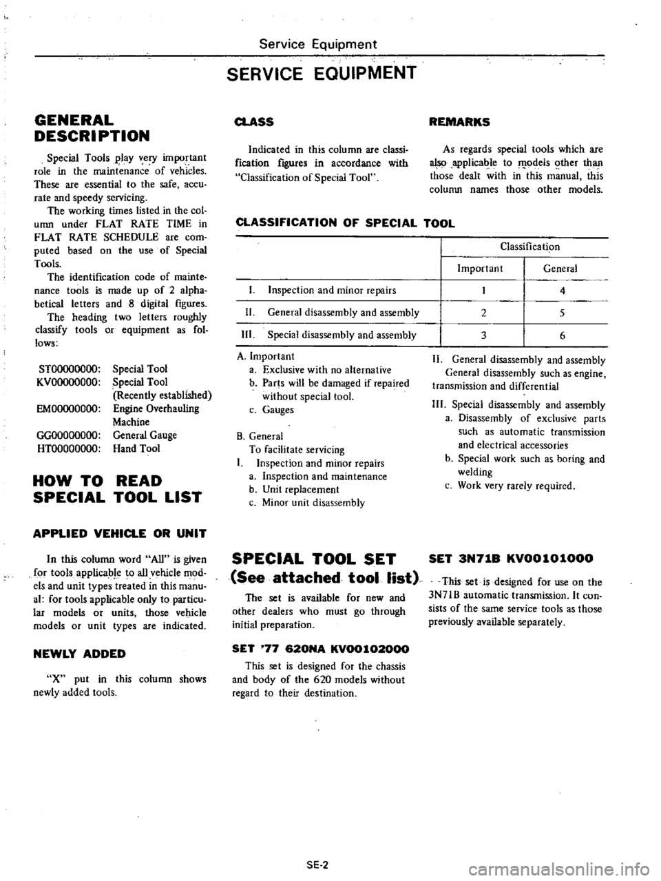
CLASSIFICATION
OF
SPECIAL
TOOL
I
Inspection
and
minor
repairs
11
General
disassembly
and
assembly
Ill
Special
disassembly
and
assembly
A
Important
a
Exclusive
with
no
alternative
b
Parts
will
be
damaged
if
repaired
without
special
tool
c
Gauges
B
General
To
facilitate
servicing
I
Inspection
and
minor
repairs
a
Inspection
and
maintenance
b
Unit
replacement
c
Minor
unit
disassembly
SPECIAL
TOOL
SET
See
attached
tool
list
The
set
is
available
for
new
and
other
dealers
who
must
go
through
initial
preparation
SET
77
620NA
KV00102000
This
set
is
designed
for
the
chassis
and
body
of
the
620
models
without
regard
to
their
destination
SE
2
Classification
Important
General
2
3
4
5
6
11
General
disassembly
and
assembly
General
disassembly
such
as
engine
transmission
and
differential
111
Special
disassembly
and
assembly
a
Disassembly
of
exclusive
parts
such
as
automatic
transmission
and
electrical
accessories
b
Special
work
such
as
boring
and
welding
c
Work
very
rarely
required
SET
3N71B
KV0010l000
This
set
is
designed
for
use
on
the
3N71B
automatic
transmission
It
con
sists
of
the
same
service
tools
as
those
previously
available
separately