suspension DATSUN PICK-UP 1977 Owner's Guide
[x] Cancel search | Manufacturer: DATSUN, Model Year: 1977, Model line: PICK-UP, Model: DATSUN PICK-UP 1977Pages: 537, PDF Size: 35.48 MB
Page 405 of 537

Condition
Wheel
wobbles
Unevenly
or
excessively
worn
tire
Tire
squeals
Wheel
and
Tire
TROUBLE
DIAGNOSES
AND
CORRECTIONS
Probable
cause
Improper
tire
pressure
Damaged
tire
or
distorted
wheel
rim
Unbalanced
wheel
Loose
wheel
nuts
Worn
or
damaged
wheel
bearing
or
excessive
play
of
wheel
bearing
Improper
front
wheel
alignment
Worn
or
damaged
ball
joint
Excessive
steering
linkage
play
or
worn
steering
linkage
Loose
steering
linkage
connection
Broken
suspension
spring
Damaged
shock
absorber
Improper
tire
rotation
Improper
tire
pressure
Unbalanced
wheel
Improperly
adjusted
brake
Improper
wheel
alignment
Excessively
distorted
or
improperly
installed
suspension
link
High
speed
on
curves
Sudden
start
and
improper
speed
due
to
rapid
acceleration
or
improper
brake
ap
plication
Improper
tire
pressure
Improper
front
wheel
alignment
Distorted
knuckle
or
suspension
link
WT
5
Corrective
action
Measure
and
adjust
Repair
or
replace
Balance
Tighten
Correct
play
or
replace
wheel
bearing
Align
Replace
Adjust
Or
replace
Tighten
nuts
to
rated
torque
or
replace
worn
parts
if
any
Replace
Replace
Conduct
tire
rotation
periodically
Measure
and
adjust
Balance
or
replace
Adjust
Align
Repair
replace
or
if
necessary
reinstall
Reduce
speed
Follow
correct
and
proper
driving
manner
Measure
and
adjust
Align
Repair
or
replace
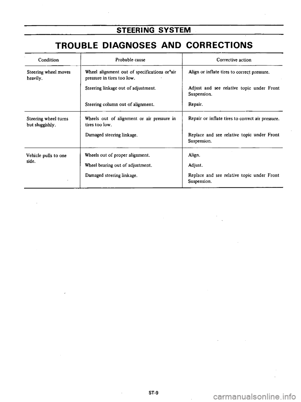
Page 414 of 537

STEERING
SYSTEM
TROUBLE
DIAGNOSES
AND
CORRECTIONS
Condition
Steering
wheel
moves
heavily
Steering
wheel
turns
but
sluggishly
Vehicle
pulls
to
one
side
Probable
cause
Wheel
alignment
out
of
specifications
or
air
pressure
in
tires
too
low
Steering
linkage
out
of
adjustment
Steering
column
out
of
alignment
Wheels
out
of
alignment
or
air
pressure
in
tires
too
low
Damaged
steering
linkage
Wheels
out
of
proper
alignment
Wheel
bearing
out
of
adjustment
Damaged
steering
linkage
ST
9
Corrective
action
Align
or
inflate
tires
to
correct
pressure
Adjust
and
see
relative
topic
under
Front
Suspension
Repair
Repair
or
inflate
tires
to
correct
air
pressure
Replace
and
see
relative
topic
under
Front
Suspension
Align
Adjust
Replace
and
see
relative
topic
under
Front
Suspension
Page 442 of 537

Body
Frame
INTERIOR
TRIM
AND
CENTER
CONSOLE
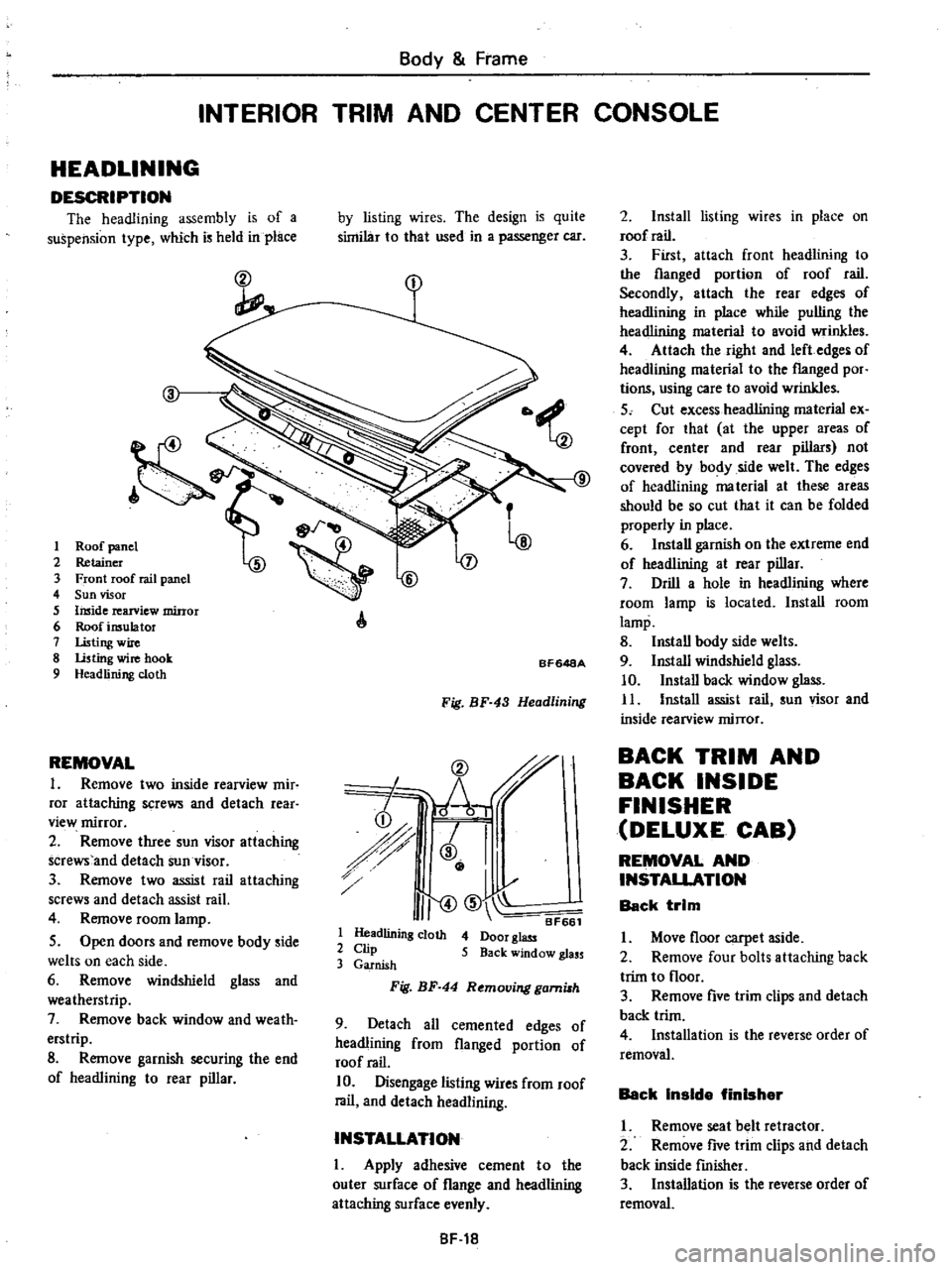
HEADLINING
DESCRIPTION
The
headlining
assembly
is
of
a
suspension
type
which
is
held
in
place
ct
I
2
3
4
5
6
7
8
9
REMOVAL
1
Remove
two
inside
rearview
mir
ror
attaching
screws
and
detach
rear
view
mirror
2
Remove
three
sun
visor
attaching
screws
and
detach
sun
visor
3
Remove
two
assist
rail
attaching
screws
and
detach
assist
rail
4
Remove
room
lamp
5
Open
doors
and
remove
body
side
welts
on
each
side
6
Remove
windshield
glass
and
weatherstrip
7
Remove
back
window
and
weath
erstrip
8
Remove
garnish
securing
the
end
of
headlining
to
rear
pillar
by
listing
wires
The
design
is
quite
similar
to
that
used
in
a
passenger
car
A
BF648A
Fig
BF
43
Headlining
CD
r
h
i
r
J
I
I
I
II
CID
BF661
1
Headlining
cloth
4
Door
glass
2
Clip
5
Back
window
glass
3
Garnish
Fig
BF
44
Removing
gami8h
9
Detach
all
cemented
edges
of
headlining
from
flanged
portion
of
roof
rail
10
Disengage
listing
wires
from
roof
rail
and
detach
headlining
INSTALLATION
I
Apply
adhesive
cement
to
the
outer
surface
of
flange
and
headlining
attaching
surface
evenly
8F
18
2
Install
listing
wires
in
place
on
roof
rail
3
First
attach
front
headlining
to
the
flanged
portion
of
roof
rail
Secondly
attach
the
rear
edges
of
headlining
in
place
while
pulling
the
headlining
material
to
avoid
wrinkles
4
Attach
the
right
and
left
edges
of
headlining
material
to
the
flanged
por
tions
using
care
to
avoid
wrinkles
5
Cut
excess
headlining
material
ex
cept
for
that
at
the
upper
areas
of
front
center
and
rear
pillars
not
covered
by
body
side
welt
The
edges
of
headlining
ma
terial
at
these
areas
should
be
so
cut
that
it
can
be
folded
properly
in
place
6
Install
garnish
on
the
extreme
end
of
headlining
at
rear
pillar
7
Drill
a
hole
in
headlining
where
room
lamp
is
located
Install
room
lamp
8
Install
body
side
welts
9
Install
windshield
glass
10
Install
back
window
glass
11
Install
assist
rail
sun
visor
and
inside
rearview
mirror
BACK
TRIM
AND
BACK
INSIDE
FINISHER
DELUXE
CAB
REMOVAL
AND
INSTALLATION
Back
trim
I
Move
floor
carpet
aside
2
Remove
four
bolts
attaching
back
trim
to
floor
3
Remove
five
trim
clips
and
detach
back
trim
4
Installation
is
the
reverse
order
of
removal
Back
Inside
finisher
I
Remove
seat
belt
retractor
2
Remove
five
trim
clips
and
detach
back
inside
fmisher
3
Installation
is
the
reverse
order
of
removal