service DATSUN PICK-UP 1977 Repair Manual
[x] Cancel search | Manufacturer: DATSUN, Model Year: 1977, Model line: PICK-UP, Model: DATSUN PICK-UP 1977Pages: 537, PDF Size: 35.48 MB
Page 343 of 537
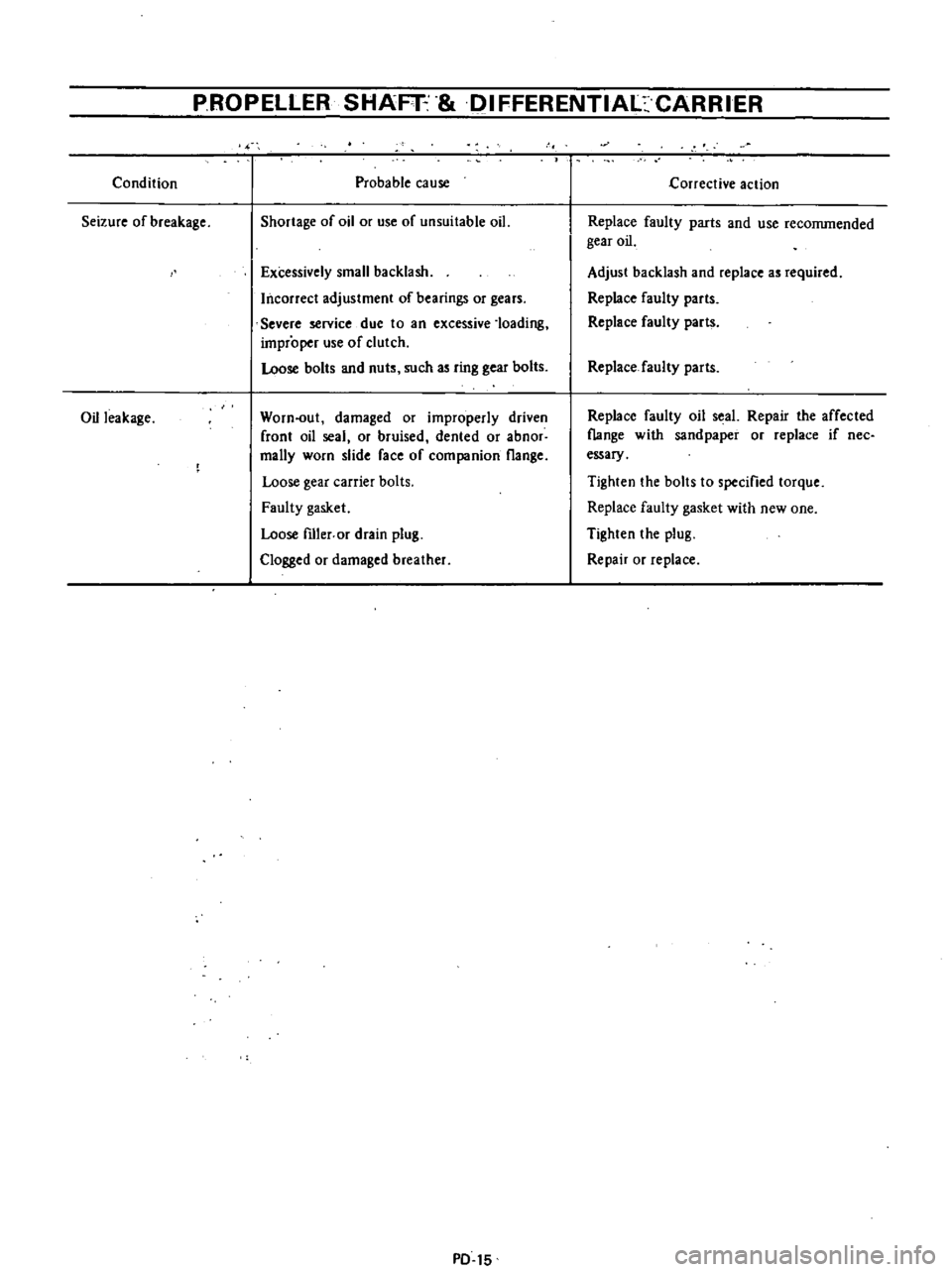
Condition
Seizure
of
breakage
Oil
leakage
PROPELLER
SHAFT
IFFERENTIAl
CARRIER
Probable
cause
Shortage
of
oil
or
use
of
unsuitable
oil
Excessively
small
backlash
Incorrect
adjustment
of
bearings
or
gears
Severe
service
due
to
an
excessive
loading
improper
use
of
clutch
Loose
bolts
and
nuts
such
as
ring
gear
bolts
Worn
out
damaged
or
improperly
driven
front
oil
seal
or
bruised
dented
or
abnor
mally
worn
slide
face
of
companion
flange
Loose
gear
carrier
bolts
Faulty
gasket
Loose
fIller
or
drain
plug
Clogged
or
damaged
breather
PD
15
1
j
Corrective
action
Replace
faulty
parts
and
use
reconunended
gear
oil
Adjust
backlash
and
replace
as
required
Replace
faulty
parts
Replace
faulty
parts
Replace
faulty
parts
Replace
faulty
oil
seal
Repair
the
affected
flange
with
sandpaper
or
replace
if
nee
essary
Tighten
the
bolts
to
specified
torque
Replace
faulty
gasket
with
new
one
Tighten
the
plug
Repair
or
replace
Page 344 of 537
PROPELLER
SHAFT
DIFFERENTIAL
CARRIER
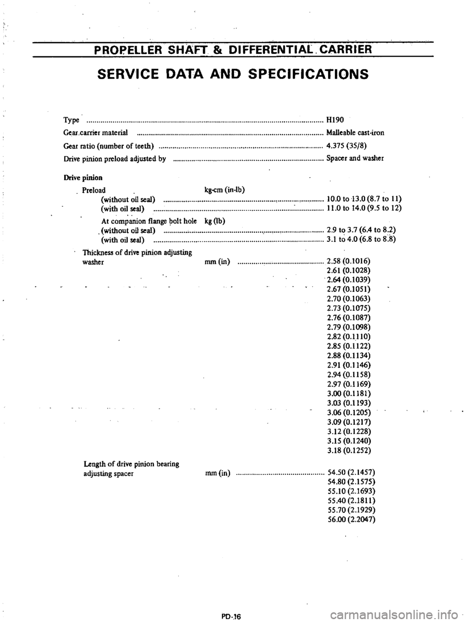
SERVICE
DATA
AND
SPECIFICATIONS
Type
Ge
ar
carrier
material
Gear
ratio
number
of
teeth
Drive
pinion
preload
adjusted
by
HI90
Malleable
cast
iron
4
375
3S
8
Spacer
and
washer
Drive
pinion
Preload
kg
cm
in
Ib
without
oil
seal
with
oil
seal
At
companion
flange
olt
hole
kg
Ib
without
oil
seal
with
oil
seal
Thickness
of
drive
pinion
adjusting
washer
nun
in
10
0
to
13
0
8
7
to
II
11
0
to
14
0
9
5
to
12
2
9
to
3
7
6
4
to
8
2
3
1
to
4
0
6
8
to
8
8
2
S8
0
1016
2
61
0
1028
2
64
0
1039
2
67
0
IOSI
2
70
0
1063
2
73
O
I07S
2
76
0
1087
2
79
0
1098
2
82
0
1110
2
8S
0
1122
2
88
0
1134
2
91
0
1146
2
94
0
1158
2
97
0
1169
3
00
0
1181
3
03
0
1193
3
06
0
120S
3
09
0
1217
3
12
0
1228
3
IS
0
1240
3
18
0
12S2
Length
of
drive
pinion
bearing
adjusting
spacer
nun
in
S4
50
2
14S7
54
80
2
IS7S
SS
IO
2
1693
SS
40
2
1811
SS
70
2
1929
S6
00
2
2047
PD
16
Page 347 of 537
PROPELLER
SHAFT
8i
DIFFERENTIALCARRIER
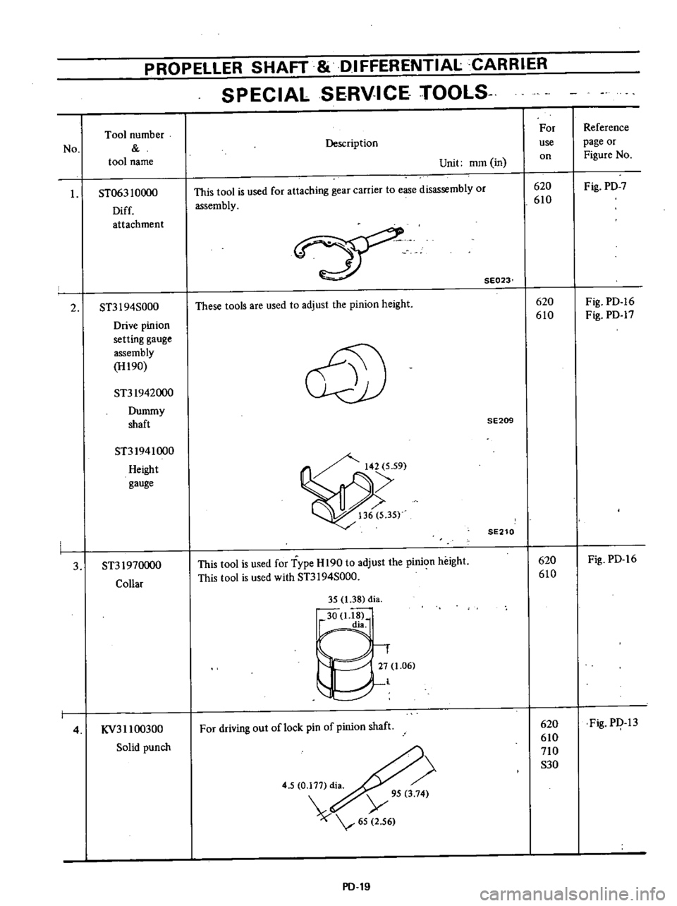
SPECIAL
SERVICE
TOOlS
No
Tool
number
tool
name
I
ST063
10000
Diff
attachment
2
ST3I
94S000
Drive
pinion
setting
gauge
assembly
H190
ST31942000
Dummy
shaft
ST31941000
Height
gauge
3
ST31970000
Collar
4
KV311
00300
Solid
punch
Description
Unit
mOl
in
This
tool
is
used
for
attaching
gear
carrier
to
ease
disassembly
or
assembly
SE023
These
tools
are
used
to
adjust
the
pinion
height
@
SE209
SE210
This
tool
is
used
for
Type
H
190
to
adjust
the
pinion
height
This
tool
is
used
with
ST3I
94S000
35
1
38
di
30
1
18
dia
1
27
1
06
l
For
driving
out
oflock
pin
of
pinion
shaft
4
5
0
177
di
Y
95
3
74
65
2
56
PD
19
For
use
on
620
610
620
610
620
610
620
610
710
S30
Reference
page
or
Figure
No
Fig
PD
7
Fig
PD
16
Fig
PD
17
Fig
PD
16
Fig
PI
13
Page 350 of 537
DATSUN
PICK
UP
MODEL
620
SERIES
lNISSAN
I
NISSAN
MOTOR
CO
LTD
TOKYO
JAPAN
r
SECTION
FA
FRONT
AXLE
FRONT
SUSPENSION
FRONT
AXLE
AND
FA
2
FRONT
SUSPENSION
SERVICE
DATA
AND
FA
13
SPECIFICATIONS
TROUBLE
DIAGNOSES
AND
FA
14
CORRECTIONS
SPECIAL
SERVICE
TOOLS
FA
17
Page 354 of 537
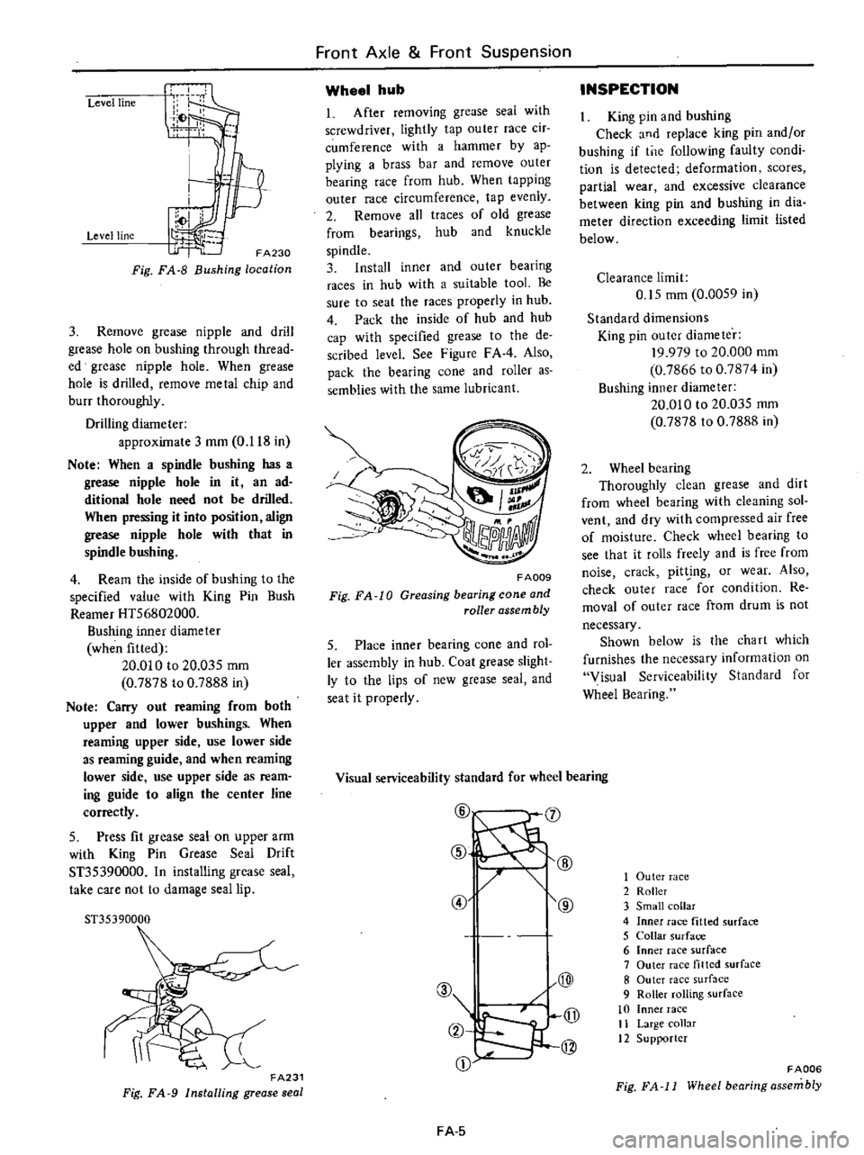
Level
line
Level
line
FA230
Fig
FA
8
Bushing
location
3
Remove
grease
nipple
and
drill
grease
hole
on
bushing
through
thread
ed
grease
nipple
hole
When
grease
hole
is
drilled
remove
metal
chip
and
burr
thoroughly
Drilling
diameter
approximate
3
mOl
0
118
in
Note
When
a
spindle
bushing
has
a
grease
nipple
hole
in
it
an
ad
ditional
hole
need
not
be
drilled
When
pressing
it
into
position
align
grease
nipple
hole
with
that
in
spindle
bushing
4
Ream
the
inside
of
bushing
to
the
specified
value
with
King
Pin
Bush
Reamer
HT56802000
Bushing
inner
diameter
when
fitted
20
010
to
20
03S
mOl
0
7878
to
0
7888
in
Note
Carry
out
reaming
from
both
upper
and
lower
bushings
When
reaming
upper
side
use
lower
side
as
reaming
guide
and
when
reaming
lower
side
use
upper
side
as
ream
ing
guide
to
align
the
center
line
correctly
5
Press
fit
grease
seal
on
upper
arm
with
King
Pin
Grease
Seal
Drift
ST35390000
In
installing
grease
seal
take
care
not
to
damage
seal
lip
51
35390000
FA231
Fig
FA
9
Installing
grease
seal
Front
Axle
Front
Suspension
Wheel
hub
1
After
removing
grease
seal
with
screwdriver
lightly
tap
outer
race
cir
cumference
with
a
hammer
by
ap
plying
a
brass
bar
and
remove
outer
bearing
race
from
hub
When
tapping
outer
race
circumference
tap
evenly
2
Remove
all
traces
of
old
grease
from
bearings
hub
and
knuckle
spindle
3
Install
inner
and
outer
bearing
races
in
hub
with
a
suitable
tool
Be
sure
to
seat
the
races
properly
in
hub
4
Pack
the
inside
of
hub
and
hub
cap
with
specified
grease
to
the
de
scribed
level
See
Figure
FAA
Also
pack
the
bearing
cone
and
roller
as
semblies
with
the
same
lubricant
FA009
Fig
FA
10
Greasing
bearing
cone
and
roller
assembly
5
Place
inner
bearing
cone
and
rol
ler
assembly
in
hub
Coat
grease
slight
ly
to
the
lips
of
new
grease
seal
and
seat
it
properly
INSPECTION
King
pin
and
bushing
Check
and
replace
king
pin
andlor
bushing
if
tne
following
faulty
condi
tion
is
detected
deformation
scores
partial
wear
and
excessive
clearance
between
king
pin
and
bushing
in
dia
meter
direction
exceeding
limit
listed
below
Clearance
limit
0
15
mOl
0
00S9
in
Standard
dimensions
King
pin
outer
diameter
19
979
to
20
000
mm
0
7866
to
0
7874
in
Bushing
inner
diameter
20
010
to
20
035
mOl
0
7878
to
0
7888
in
2
Wheel
bearing
ThorougWy
clean
grease
and
dirt
from
wheel
bearing
with
cleaning
sol
vent
and
dry
with
compressed
air
free
of
moisture
Check
wheel
bearing
to
see
that
it
rolls
freely
and
is
free
from
noise
crack
pit
ing
or
wear
Also
check
outer
race
for
condition
Re
moval
of
outer
race
from
drum
is
not
necessary
Shown
below
is
the
cha
rt
which
furnishes
the
necessary
information
on
Visual
Serviceability
Standard
for
Wheel
Bearing
Visual
serviceability
standard
for
wheel
bearing
@
J
@
@
@
@
@
A
Q
jJ
2
@
CD
FA
5
1
Outer
race
2
Roller
3
Small
collar
4
Inner
race
fitted
surface
5
Collar
surface
6
Inner
race
surface
7
Outer
race
tilted
surface
8
Outer
race
surf
lcc
9
Roller
rolling
surface
10
Inner
race
11
Large
collar
12
Supporter
FADD6
Fig
FA
11
Wheel
bearing
assembly
Page 355 of 537
Front
Axle
Front
Suspension
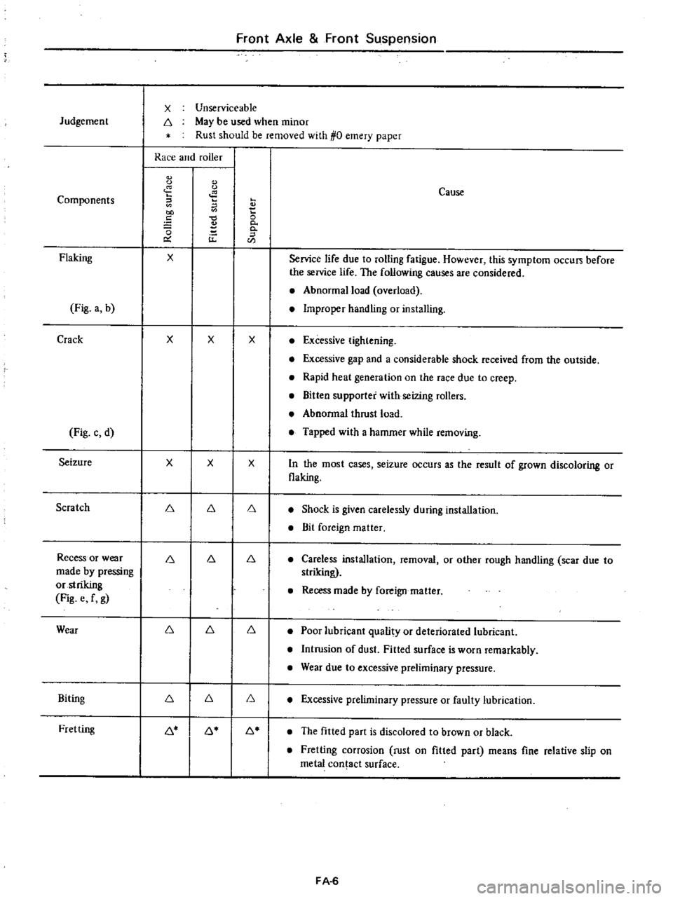
X
Unserviceable
Judgement
6
May
be
used
when
minor
Rust
should
be
removed
with
0
emery
paper
Race
and
roller
C
Cause
Components
E
2
e
0
0
0
0
u
0
CIl
Flaking
X
Service
life
due
to
rolling
fatigue
However
this
symptom
occu
before
the
service
life
The
following
causes
are
considered
Abnormal
load
overload
Fig
a
b
Improper
handling
or
installing
Crack
X
X
X
Excessive
tightening
Excessive
gap
and
a
considerable
shock
received
from
the
outside
Rapid
heat
generation
on
the
race
due
to
creep
Bitten
supporter
with
seizing
rollers
Abnormal
thrust
load
Fig
c
d
Tapped
with
a
hammer
while
removing
Seizure
X
X
X
n
the
most
cases
seizure
occurs
as
the
result
of
grown
discoloring
or
flaking
Scratch
6
6
6
Shock
is
given
carelessly
during
installation
Bit
foreign
matter
Recess
or
wear
6
6
6
Careless
installation
removal
or
other
rough
handling
scar
due
to
made
by
pressing
striking
or
striking
Recess
made
by
foreign
matter
Fig
e
f
g
Wear
6
6
6
Poor
lubricant
quality
or
deteriorated
lubricant
Intrusion
of
dust
Fitted
surface
is
worn
remarkably
Wear
due
to
excessive
preliminary
pressure
Biting
6
6
6
Excessive
preliminary
pressure
or
faulty
lubrication
Fretting
6
6
6
The
fitted
part
is
discolored
to
brown
or
black
Fretting
corrosion
rust
on
fitted
part
means
fine
relative
slip
on
metal
contact
surface
FA
6
Page 362 of 537
Front
Axle
Front
Suspension
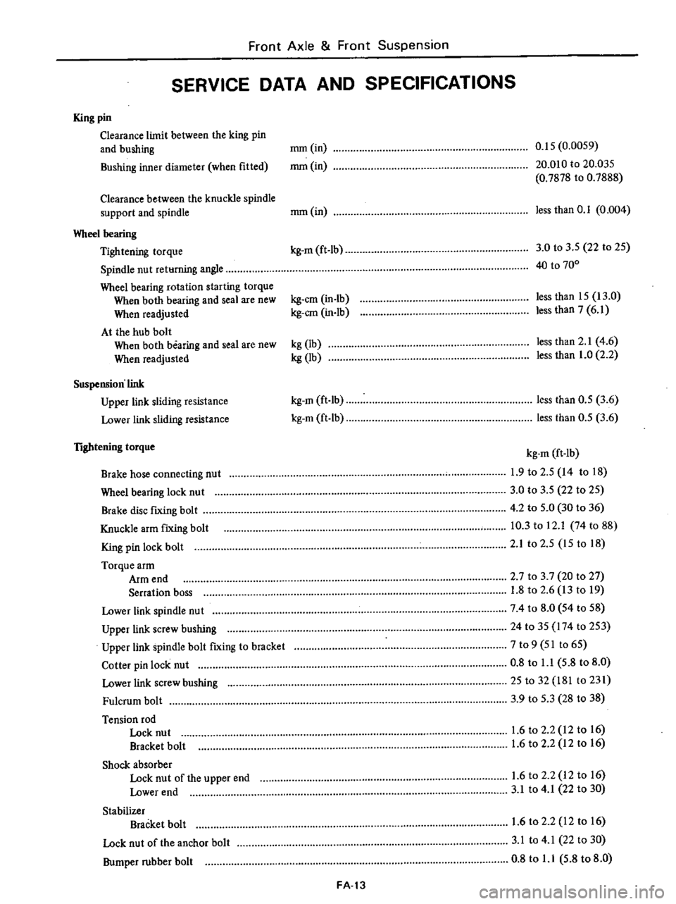
SERVICE
DATA
AND
SPECIFICATIONS
King
pin
Clearance
limit
between
the
king
pin
and
bushing
mm
in
0
15
0
0059
Bushing
inner
diameter
when
fitted
mm
in
20
010
to
20
035
0
7878
to
0
7888
Clearance
between
the
knuckle
spindle
support
and
spindle
mm
in
less
than
0
1
0
004
Wheel
bearing
Tightening
torque
kg
m
ft
Ib
3
0
to
3
S
22
to
2S
Spindle
nut
returning
angle
40
to
700
Wheel
bearing
rotation
starting
torque
When
both
bearing
and
seal
are
new
kg
em
in
Ib
less
than
IS
13
0
When
readjusted
kg
em
in
lb
less
than
7
6
1
At
the
hub
bolt
When
both
bearing
and
seal
are
new
kg
lb
less
than
2
1
4
6
When
readjusted
kg
lb
less
than
1
0
2
2
Suspension
link
Upper
link
sliding
resistance
kg
m
ft
Ib
less
than
O
S
3
6
Lower
link
sliding
resistance
kg
m
ft
lb
less
than
O
S
3
6
lightening
torque
kg
m
ft
Ib
Brake
hose
connecting
nut
1
9
to
2
S
14
to
18
Wheel
bearing
lock
nu
t
3
0
to
3
5
22
to
2S
Brake
disc
fIXing
bolt
4
2
to
S
O
30
to
36
Knuckle
arm
fixing
bolt
10
3
to
12
1
74
to
88
King
pin
lock
bolt
2
1
to
2
S
IS
to
18
Torque
arm
Arm
end
2
7
to
3
7
20
to
27
Serration
boss
1
8
to
2
6
13
to
19
Lower
link
spindle
nut
74
to
8
0
S4
to
58
Upper
link
screw
bushing
24
to
35
174
to
2S3
Upper
link
spindle
bolt
fIXing
to
bracket
7
to
9
51
to
6S
Cotter
pin
lock
nut
0
8
to
l
l
5
8
to
8
0
Lower
link
screw
bushing
25
to
32
181
to
231
Fulcrum
bolt
3
9
to
S
3
28
to
38
Tension
rod
Lock
nut
1
6
to
2
2
12
to
16
Bracket
bolt
1
6
to
2
2
12
to
16
Shock
absorber
Lock
nut
of
the
upper
end
1
6
to
2
2
12
to
16
Lower
end
3
1
to
4
1
22
to
30
Stabilizer
Bracket
bolt
1
6
to
2
2
12
to
16
Lock
nut
of
the
anchor
bolt
3
1
to
4
1
22
to
30
Bumper
rubber
bolt
0
8
to
l
l
5
8
to
8
0
FA
13
Page 366 of 537
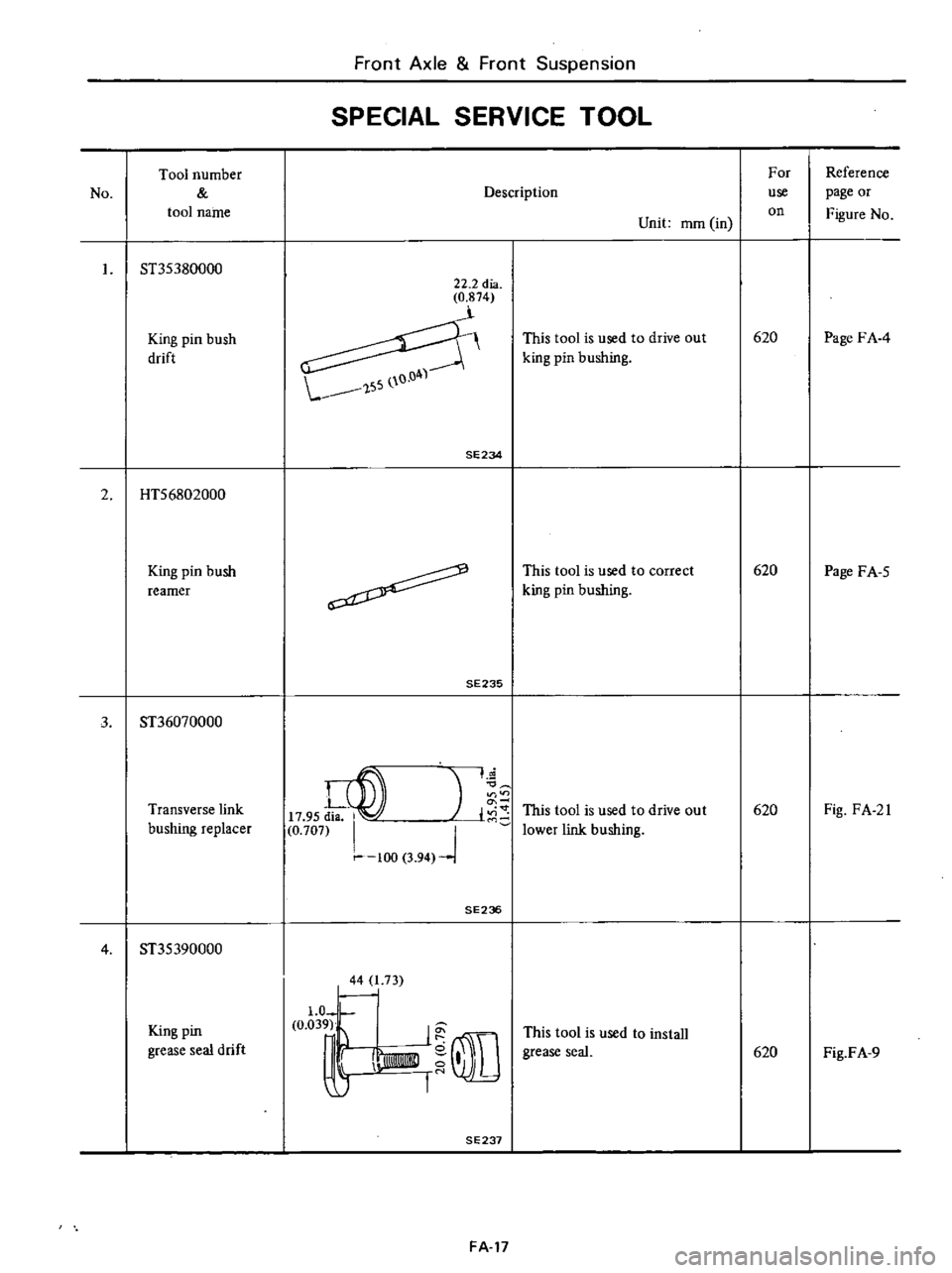
No
Tool
number
tool
name
ST35380000
King
pin
bush
drift
2
HTS6802000
King
pin
bush
reamer
Front
Axle
Front
Suspension
SPECIAL
SERVICE
TOOL
22
2
dia
0
874
SE234
FA
17
Description
Unit
mOl
in
This
tool
is
used
to
drive
out
king
pin
bushing
This
tool
is
used
to
correct
king
pin
bushing
For
use
on
620
620
Reference
page
or
Figure
No
Page
FA
4
Page
FA
S
Page 367 of 537
DATSUN
PICK
UP
MODEL
620
SERIES
I
NISSAN
I
NISSAN
MOTOR
CO
LTD
TOKYO
JAPAN
SECTION
RA
REAR
AXLE
REAR
SUSPENSION
REAR
AXlE
AND
RA
2
REAR
SUSPENSION
SERVICE
DATA
AND
RA
7
SPECIFICATIONS
TROUBLE
DIAGNOSES
RA
8
AND
CORRECTIONS
SPECIAL
SERVICE
TOOLS
RA
9
Page 372 of 537
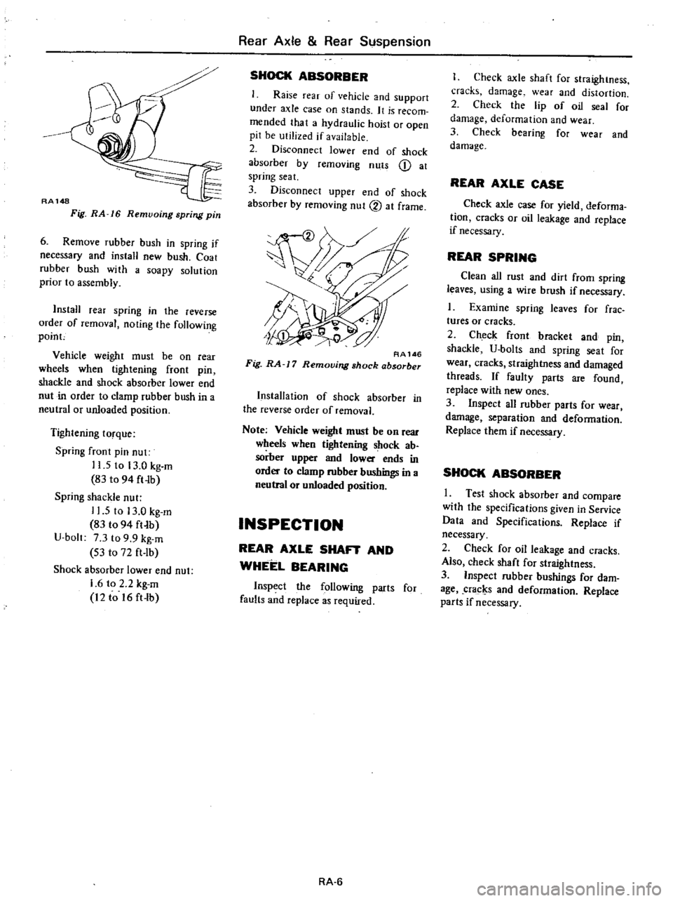
RA148
Fig
RA
16
Remvoing
spring
pin
6
Remove
rubber
bush
in
spring
if
necessary
and
install
new
bush
Coat
rubber
hush
with
a
soapy
solution
prior
to
assembly
InstaH
rear
spring
in
the
reverse
order
of
removal
noting
the
following
poinc
Vehicle
weight
must
be
on
rear
wheels
when
tightening
front
pin
shackle
and
shock
absorber
lower
end
nut
in
order
to
clamp
rubber
bush
in
a
neutral
or
unloaded
position
Tightening
torque
Spring
fTont
pin
nut
11
5
to
13
0
kg
m
83
to
94
ft
Ib
Spring
shackle
nut
11
5
to
13
0
kg
m
83
t094
ft
b
U
bolt
7
3
to
9
9
kg
m
S3
to
72
ft
lb
Shock
absorber
lower
end
nut
1
6
to
2
2
kg
m
12
to
16
ft
lb
Rear
Axle
Rear
Suspension
SHOCK
ABSORBER
Raise
rear
of
vehicle
and
support
under
axle
case
on
stands
It
is
recom
mended
that
a
hydraulic
hoist
or
open
pit
be
utilized
if
available
2
Disconnect
lower
end
of
shock
absorber
by
removing
nuts
Q
at
spring
seat
3
Disconnect
upper
end
of
shock
absorber
by
removing
nut
2
at
frame
RA146
Fig
RA
J
7
Removing
shock
absorber
Installation
of
shock
absorber
in
the
reverse
order
of
removal
Note
Vehicle
weight
must
be
on
Tear
wheels
when
tigtrtening
shock
ab
sorber
upper
and
lower
ends
in
order
to
clamp
rubber
bushings
in
a
neutral
or
unloaded
position
INSPECTION
REAR
AXLE
SHAFT
AND
WHEEL
BEARING
Inspect
the
following
parts
for
faults
and
replace
as
required
RA
6
I
Check
axle
shaft
for
straightness
cracks
damage
wear
and
distortion
2
Check
the
lip
of
oil
seal
for
damage
deformation
and
wear
3
Check
bearing
for
wear
and
damage
REAR
AXLE
CASE
Check
axle
case
for
yield
deforma
tion
cracks
or
oil
leakage
and
replace
if
necessary
REAR
SPRING
Clean
all
rust
and
dirt
from
spring
leaves
using
a
wire
brush
if
necessary
1
Examine
spring
leaves
for
frae
tures
or
cracks
2
Check
front
bracket
and
pin
shackle
U
bolts
and
spring
seat
for
wear
cracks
straightness
and
damaged
threads
If
faulty
parts
are
found
replace
with
new
ones
3
Inspect
all
rubber
parts
for
wear
damage
separation
and
deformation
Replace
them
if
necessary
SHOCK
ABSORBER
I
Test
shock
absorber
and
compare
with
the
specifications
given
in
Service
Data
and
Specifications
Replace
if
necessary
2
Check
for
oil
leakage
and
cracks
Also
check
shaft
for
straightness
3
Inspect
rubber
bushings
for
dam
age
cracl
s
and
deformation
Replace
parts
if
necessary