service DATSUN PICK-UP 1977 Owner's Manual
[x] Cancel search | Manufacturer: DATSUN, Model Year: 1977, Model line: PICK-UP, Model: DATSUN PICK-UP 1977Pages: 537, PDF Size: 35.48 MB
Page 117 of 537
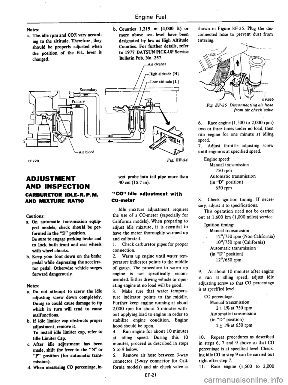
Notes
a
The
idle
rpm
and
CO
vary
accord
ing
to
the
altitude
Therefore
they
should
be
properly
adjusted
when
the
position
of
the
H
L
lever
is
changed
EF729
ADJUSTMENT
AND
INSPECTION
CARBURETOR
IDLE
R
P
M
AND
MIXTURE
RATIO
Cautions
3
On
automatic
transmission
equi
ped
models
check
should
be
per
formed
in
the
0
position
Be
sure
to
engage
parking
brake
and
to
lock
both
front
and
rear
wheels
with
wheel
chocks
b
Keep
your
foot
down
on
the
brake
pedal
while
depressing
the
accelera
tor
pedal
Otherwise
vehicle
surges
forward
dangerously
Notes
a
00
not
attempt
to
screw
the
idle
adjusting
screw
down
completely
Ooing
so
could
cause
damage
to
tip
which
in
turn
will
tend
to
cause
malfunctio11ll
b
If
idle
limiter
cap
obstructs
proper
adjustment
remove
it
To
install
idle
limiter
cap
refer
to
Idle
Limiter
Cap
c
After
idle
adjustment
has
been
made
shift
the
lever
to
the
N
or
P
position
for
automatic
trans
mission
d
When
measuring
CO
percentage
in
Engine
Fuel
b
Counties
1
219
m
4
000
ft
or
more
above
sea
level
have
been
designated
by
law
as
High
Altitude
Counties
For
further
details
refer
to
1977
OATSUN
PICK
UP
Service
Bulletin
Pub
No
257
0
I
Air
cleaner
rID
mOl
If
Low
altitude
Ll
n
n
L
n
Fig
EF
34
sert
probe
into
tail
pipe
more
than
40
em
15
7
in
CO
Idle
adjustment
with
CO
meter
Idle
mixture
adjustment
requires
the
use
of
a
CO
meter
especially
for
California
models
When
preparing
to
adjust
idle
mixture
it
is
essential
to
have
the
meter
thoroughly
warmed
up
and
calibrated
I
Check
carburetor
pipes
for
proper
connection
2
Warm
up
engine
until
water
tem
perature
indicator
points
to
the
middle
of
gauge
The
procedure
to
warm
up
engine
is
not
specifically
recom
mended
Either
driving
vehicle
or
oper
ating
engine
at
no
load
will
be
good
3
Make
sure
that
water
tempera
ture
indicator
points
to
the
middle
Further
keep
engine
running
at
about
2
000
rpm
for
about
5
minutes
with
out
applying
load
to
engine
in
order
to
stabilize
engine
condition
Engine
hood
should
be
open
4
Run
engine
for
about
10
minutes
at
idling
speed
Ouring
this
10
minutes
proceed
as
described
in
steps
5
to
9
below
5
Remove
air
hose
between
3
way
connector
5
way
connector
for
Cali
fornia
models
and
air
check
valve
as
EF
21
shown
in
Figure
EF
35
Plug
the
dis
connected
hose
to
prevent
dust
from
entering
0
o
EF259
Fig
EF
35
Disconnecting
air
hose
from
air
check
valve
6
Race
engine
I
500
to
2
000
rpm
two
or
three
times
under
no
load
then
run
engine
for
one
minute
at
idling
speed
7
Adjust
throttle
adjusting
screw
until
engine
is
at
specified
speed
Engine
speed
Manual
transmission
750
rpm
Automatic
transmission
in
0
position
650
rpm
8
Check
ignition
timing
If
neces
sary
adjust
it
to
specifications
This
operation
need
not
be
carried
out
at
1
600
Ian
1
000
miles
service
Ignition
timing
Manual
transmission
120
750
rpm
Non
California
100
750
rpm
California
Automatic
transmission
in
0
position
120
650
rpm
9
At
about
10
minutes
after
engine
is
run
at
idling
speed
adjust
idle
adjusting
screw
so
that
CO
percentage
is
at
specified
level
CO
percentage
Manual
transmission
2
t
l
at
750
rpm
Automatic
transmission
in
0
position
2
t
I
at
650
rpm
10
Repeat
procedures
as
described
in
steps
6
7
and
9
above
so
that
CO
percentage
is
at
specified
level
Check
ing
idle
CO
in
step
9
can
be
carried
out
right
after
step
7
II
Race
engine
1
500
to
2
000
Page 118 of 537
rpm
two
or
three
iimes
under
no
load
and
make
sure
that
specified
CO
per
centage
is
obtained
12
Connect
air
hose
to
air
check
valve
If
engine
speed
increases
readjust
it
to
the
specified
speed
with
throttle
adjustingsqew
CO
idle
edJustment
without
CO
meter
If
CO
meter
is
not
available
the
following
procedures
may
be
used
L
Check
carburetor
pipes
for
proper
connection
2
Warm
up
engine
until
water
tem
perature
indicator
points
to
the
middle
of
gauge
The
procedure
to
warm
up
engine
is
not
specifically
recom
mended
Either
driving
vehicle
or
oper
ating
engine
at
no
load
will
be
good
3
Make
sure
that
water
temperature
indicator
points
to
the
middle
Further
keep
engine
running
at
about
2
000
rpm
for
about
5
minutes
without
applying
load
to
engine
in
order
to
stabilize
engine
condition
Engine
hood
should
be
open
4
Run
engine
for
about
10
minutes
at
idling
speed
During
this
10
minutes
proceed
as
described
in
steps
5
to
9
below
5
Remove
air
hose
between
3
way
connector
5
way
connector
for
Cali
fornia
models
and
air
check
valve
shown
in
Figure
EF
35
Plug
the
dis
connected
hose
19
prevent
dust
from
entering
6
Race
engine
1
500
to
2
000
rpm
two
or
three
times
under
no
load
then
run
engine
for
one
minute
at
idling
speed
7
Adjust
throttle
adjusting
screw
so
that
engine
speeds
are
as
indicated
below
Engine
speed
Manual
transmission
815
rpm
Automatic
transmission
in
D
position
670
rpm
8
Check
ignition
timing
if
neces
sary
adjust
it
to
the
value
required
by
specifications
This
operation
need
not
be
carried
out
at
1
600
km
1
000
miles
service
9
At
about
10
minutes
after
engine
Engine
Fuel
is
run
at
idling
speed
adjust
idle
adjusting
screw
until
maximum
rpm
is
obtained
10
Repeat
procedures
as
described
in
steps
6
7
and
9
above
until
engine
speed
at
best
idle
mixture
is
815
rpm
for
manual
transmission
models
and
670
rpm
for
automatic
transmission
models
in
D
position
Adjustment
in
step
9
can
be
carried
out
right
after
step
7
11
Turn
the
idle
adjusting
screw
clockwise
until
engine
speed
drops
off
below
specified
rpm
Engine
speed
drops
off
Manual
transmission
60
to
70
rpm
Automatic
transmission
in
D
position
15
to
25
rpm
12
Connect
air
hose
to
air
check
valve
If
engine
speed
increases
readjust
it
to
the
specified
speed
with
throttle
adjusting
screw
Idle
limiter
cep
Do
not
remove
this
idle
limiter
cap
unless
necessary
If
this
unit
is
re
moved
it
must
be
readjusted
at
lime
of
installation
To
adjust
proceed
as
follows
I
After
adjusting
throttle
or
idle
speed
adjusting
screw
check
to
be
sure
that
the
amount
of
CO
contained
in
exhaust
gases
meets
the
established
standard
2
Install
idle
limiter
cap
in
position
making
sure
that
the
adjusting
screw
can
rotate
another
1
8
turn
in
the
CO
RICH
direction
Carbo
to
per
CO
rich
450
lIS
rotation
t
CO
lean
J
SQ
dl
lim
ET031
1
e
Iter
cap
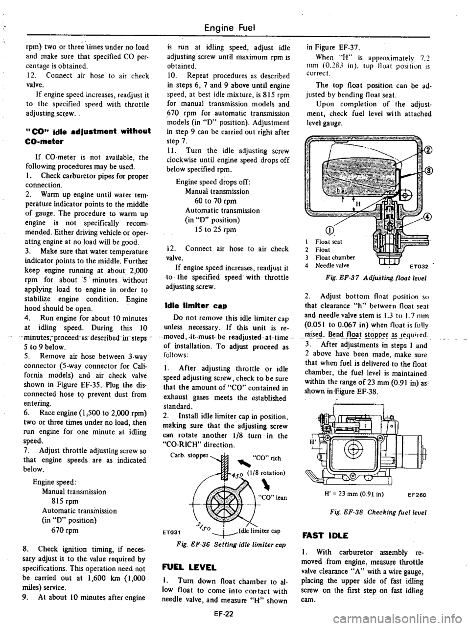
Fig
EF
36
Setting
idle
limiter
cap
FUEL
LEVEL
1
Turn
down
float
chamber
to
al
low
float
to
come
into
contact
with
needle
valve
and
measure
Hu
shown
EF
22
in
Figu
re
EF
37
When
H
is
approximalely
7
mill
0
283
in
lOp
float
position
is
correct
The
top
float
position
can
be
ad
justed
by
bending
float
seat
Upon
completion
of
the
adjust
ment
check
fuel
level
wi
th
attached
level
gauge
p
j
i
I
it
I
Float
seat
2
Float
3
Float
chamber
4
Needle
valve
t
I
IIf
ET032
Fig
EF
37
Adjusting
float
level
2
Adjust
bottom
float
position
so
that
clearance
h
between
float
seat
and
needle
valve
stemis
I
3
to
L
7
mm
0
051
to
0
067
in
when
Iloat
is
fully
rals
n
Jloa
t
goppe
q
re
3
After
adjustments
in
steps
I
and
2
above
have
been
made
make
sure
that
when
fuel
is
delivered
to
the
float
chamber
the
fuel
level
is
maintained
within
the
range
of23
mm
0
91
in
as
shown
in
FigureEF
38
H
23
mm
0
91
in
EF260
Fig
EF
38
Checking
ruellevel
FAST
IDLE
I
With
carburetor
assembly
reo
moved
from
engine
measure
throttle
valve
clearance
A
with
a
wire
gauge
placing
the
upper
side
of
fast
idling
screw
on
the
first
step
on
fast
idling
cam
Page 125 of 537
I
Set
circuit
tester
in
d
c
ampere
range
IA
min
fuU
scale
connect
test
probes
of
tester
as
shown
in
Figure
EF
58
Do
not
confuse
positive
line
with
negative
line
2
Turn
ignition
key
to
ON
posi
tion
I
t
EF264
1
Ignition
key
2
Amplifier
3
Speed
detecting
switch
4
B
C
D
D
solenoid
valve
Inhibitor
switch
Automatic
transmission
models
Refer
to
the
AT
section
Inhibitor
relay
Automatic
transmission
models
Inhibitor
relay
EF724
Fig
EF
59
Location
of
inhibitor
relay
2
Make
an
inhibitor
relay
check
as
shown
in
Figure
EF
60
Apply
12
volts
d
c
across
termi
nals
1
and
4
to
ensure
that
continuity
exists
between
terminals
2
and
3
Check
that
continuity
does
not
exist
between
terminals
2
and
3
when
no
voltage
is
applied
across
them
Engine
Fuel
3
Ensure
that
tester
pointer
deflects
when
ignition
key
is
turned
on
4
If
tester
pointer
does
not
deflect
when
solenoid
valve
and
speed
detect
ing
switch
circuits
are
functioning
properly
amplifier
is
faulty
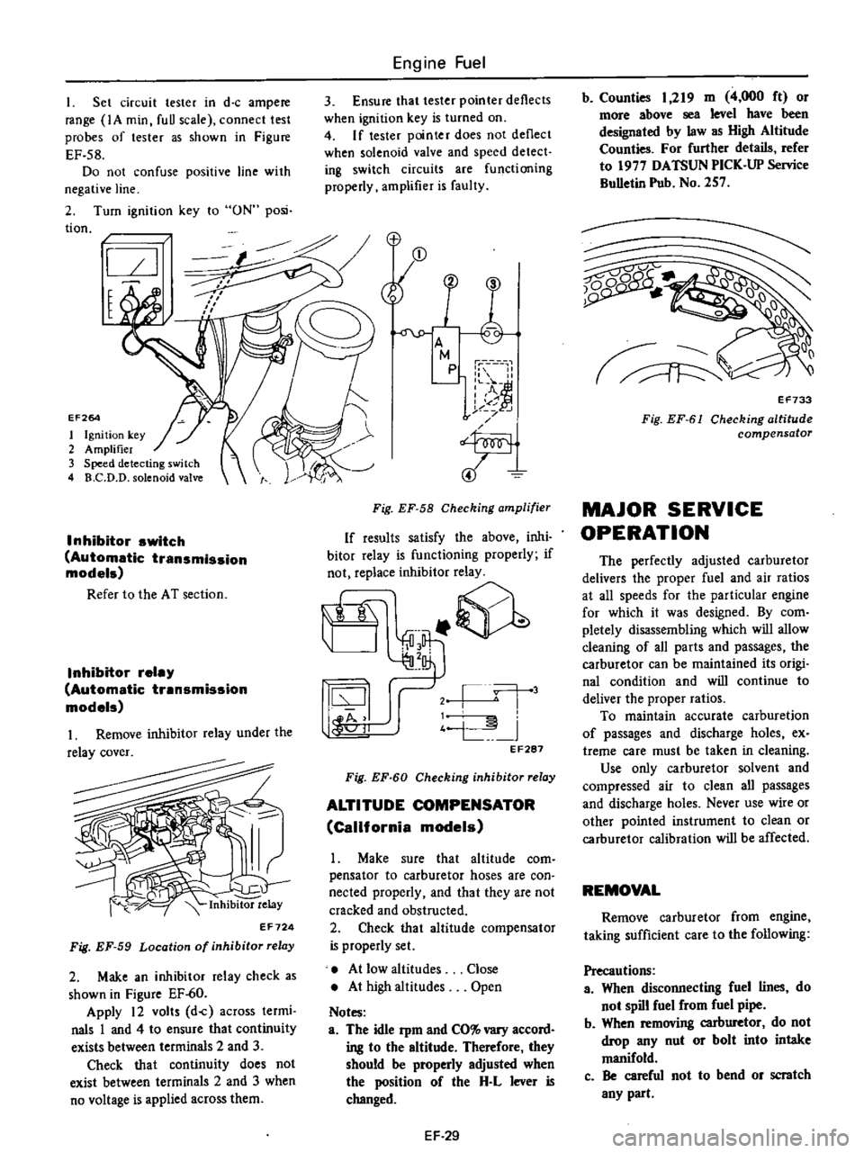
Fig
EF
58
Checking
amplifier
If
results
satisfy
the
above
inhi
bitor
relay
is
functioning
properly
if
not
replace
inhibitor
relay
it
@
j
l
j
4
L
I
44
11
oJ
EF287
Fig
EF
60
Checking
inhibitor
relay
ALTITUDE
COMPENSATOR
California
models
Make
sure
that
altitude
com
pensator
to
carburetor
hoses
are
con
nected
properly
and
that
they
are
not
cracked
and
obstructed
2
Check
that
altitude
compensator
is
properly
set
At
low
altitudes
At
high
altitudes
Notes
a
The
idle
Pm
and
CO
vary
accord
ing
to
the
altitude
Therefore
they
should
be
properly
adjusted
when
the
position
of
the
H
L
lever
is
changed
Close
Open
EF
29
b
Counties
1
219
m
4
000
ft
or
more
above
sea
level
have
been
designated
by
law
as
High
Altitude
Counties
For
further
details
refer
to
1977
DATSUN
PICK
UP
Service
BuUetin
Pub
No
257
Q0
1
v
EF733
Fig
EF
61
Checking
altitude
compensator
MAJOR
SERVICE
OPERATION
The
perfectly
adjusted
carburetor
delivers
the
proper
fuel
and
air
ratios
at
all
speeds
for
the
particular
engine
for
which
it
was
designed
By
com
pletely
disassembling
which
will
allow
deaning
of
all
parts
and
passages
the
carburetor
can
be
maintained
its
origi
nal
condition
and
will
continue
to
deliver
the
proper
ratios
To
maintain
accurate
carburetion
of
passages
and
discharge
holes
ex
treme
care
must
be
taken
in
cleaning
Use
only
carburetor
solvent
and
compressed
air
to
clean
all
passages
and
discharge
holes
Never
use
wire
or
other
pointed
instrument
to
clean
or
carburetor
calibration
will
be
affected
REMOVAL
Remove
carburetor
from
engine
taking
sufficient
care
to
the
following
Precautions
a
When
disconnecting
fuel
lines
do
not
spill
fuel
from
fuel
pipe
b
When
removing
carburetor
do
not
drop
any
nut
or
bolt
into
intake
manifold
c
Be
careful
not
to
bend
or
scratch
any
part
Page 131 of 537
Engine
Fuel
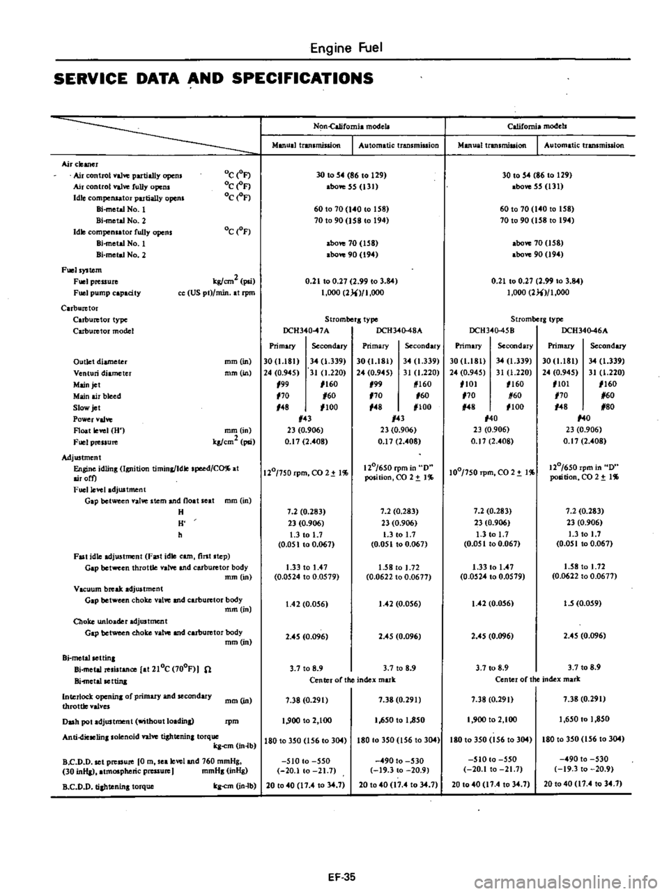
SERVICE
DATA
AND
SPECIFICATIONS
Airclelllcr
Ail
control
val
partially
opem
Air
ntrol
valve
fuUy
opens
Idle
ompensatoI
partially
opens
Hi
mettiNo
l
Bi
metal
No
2
Idle
ompen
tor
fully
opens
Bi
metal
No
1
Hi
metd
No
2
Fuels
Stem
Fuel
prtuure
Fuel
pump
apacHy
C
rbu
tor
C
rbu
tor
type
Carburetor
model
Oc
oF
oCe
F
oCe
F
Oc
OF
kpJcm2
poi
US
pt
min
at
rpm
Outlet
diameter
Venturi
diameter
Main
jet
Main
air
bleed
Slow
jet
Power
val
Float
level
U
fuel
preuure
rom
in
mm
in
mm
in
kg
cm2
psi
Adjustment
Engine
idling
Ignition
timing
Idle
speed
CO
at
mloro
Fuel
level
adjustment
Gap
between
Ive
stem
and
noat
at
mm
in
H
H
h
Fast
idle
adjwtmcnt
Fast
idle
earn
tint
step
Gap
between
throttle
IYe
and
carburetor
body
mm
in
Vacuum
break
adjustment
Gap
between
choke
alve
and
carburetor
body
mm
in
Choke
unloadel
adjusttncnt
Gap
between
choke
alw
and
carburetor
body
rom
in
Bi
metalsettinl
Bi
metal
resistance
at
2Ioe
700F
n
Bi
metalsettina
lnterloc
k
opcnina
of
primary
and
secondary
throtUc
valves
mmOn
Duh
pot
adjustment
without
loadin
I
m
Anti
diclClinasolenoid
valV
C
tiahtenina
torque
ka
m
in
lb
a
c
D
D
set
p
JSure
0
m
sea
level
and
760
mmHg
30
inlla
atmospheric
pressure
J
mmHa
inHg
R
C
D
D
tiahteninl
torque
kg
m
n
b
Nl
n
California
modell
Manual
transmiSsion
I
Automatic
transmission
California
modeb
Manual
transmission
I
Automatic
transmission
30
to
54
86
to
129
above
55
131
30
to
54
86
to
129
above
55
131
60
to
70
140
to
158
70
to
90
158
to
194
60
to
70
140
to
158
70
to
90
158
to
194
above
70
158
above
90
194
above
70
158
above
90
194
0
21
to
0
27
2
99
to
3
84
t
OOO
2
i
I
OOO
0
21
to
0
27
2
99
to
3
84
1
000
2
i
I
OOO
Strombcra
type
OCH340
7A
DCH340
48A
Stromt
rg
type
DCH34Q
45B
DCH340
46A
Primary
Secondary
Primary
Secondary
Primary
Secondary
Primary
Secondary
30
I8t
340
339
30
1
181
34
1
339
30
1
181
34
1
339
30
1
181
34
1
339
24
0
945
310
220
24
0
945
31
1
220
24
0
945
31
1
220
24
0
945
31
1
220
199
1160
199
1160
1101
1160
101
1160
170
160
170
160
170
60
170
1
60
148
1100
148
1100
148
1100
148
180
143
143
140
140
23
0
906
23
0
906
23
0
906
23
0
906
0
17
2
408
0
17
2
40B
0
17
2
408
0
17
2
408
1201750
rpm
CO
2
1
120
650
rpm
0
100
750rpm
C02
t
1
120
650
rpm
0
position
CO
2
t
1
position
CO
2
t
1
7
2
0
283
7
2
0
283
7
2
0
283
7
2
0
283
23
0
906
23
0
906
23
0
906
23
0
906
1
3
to
1
7
1
3
to
1
7
1
3
to
1
7
1
3
to
1
7
0
051
to
0
067
0
051
to
0
067
0
051
to
0
067
0
051
to
0
067
1
33
to
1
47
1
58
to
1
72
1
33
to
1
47
1
58
to
1
72
0
0524
to
0
0579
0
0622
to
0
0677
0
0524
to
0
0579
0
0622
to
0
0677
1
42
0
056
1
42
0
056
1
42
0
056
1
5
0
059
2
45
0
096
2
45
0
096
2
4
0
096
2
45
0
096
3
7
to
8
9
3
7
to
8
9
3
7
to
B
9
3
7
to
8
9
Center
of
the
ndex
mark
Center
of
the
index
mark
7
38
0
291
7
38
0
291
7
38
0
290
7
38
0
291
1
900
to
2
100
1
650
to
1
850
1
900
to
2
100
1
650
to
1
850
180
to
350
156
to
304
180
to
350
156
to
304
180
to
350
156
to
304
180
to
350
156
to
304
510
to
550
490
to
530
510
to
550
490
to
530
20
1
to
21
7
19
3
to
20
9
20
1
to
21
7
19
3
to
20
9
20
to
40
17
4
to
34
1
20
to
40
11
4
to
34
7
20
to
40
17
4
to
34
7
20
to
40
17
4
to
34
1
EF
35
Page 134 of 537
DATSUN
PICK
UP
MODEL
620
SERIES
I
NISSANI
NISSAN
MOTOR
CO
LTD
TOKYO
JAPAN
SECTION
EC
EMISSION
CONTROL
SYSTEM
EC
2
GENERAl
DESCRIPTION
CRANKCASE
EMISSION
CONTROL
SYSTEM
EXHAUST
EMISSION
CONTROL
SySTEM
EC
3
EVAPORATIVE
EMISSION
CONTROL
SYSTEM
SPECIAL
SERVICE
TOOLS
EC
2
EC
30
EC
32
Page 155 of 537
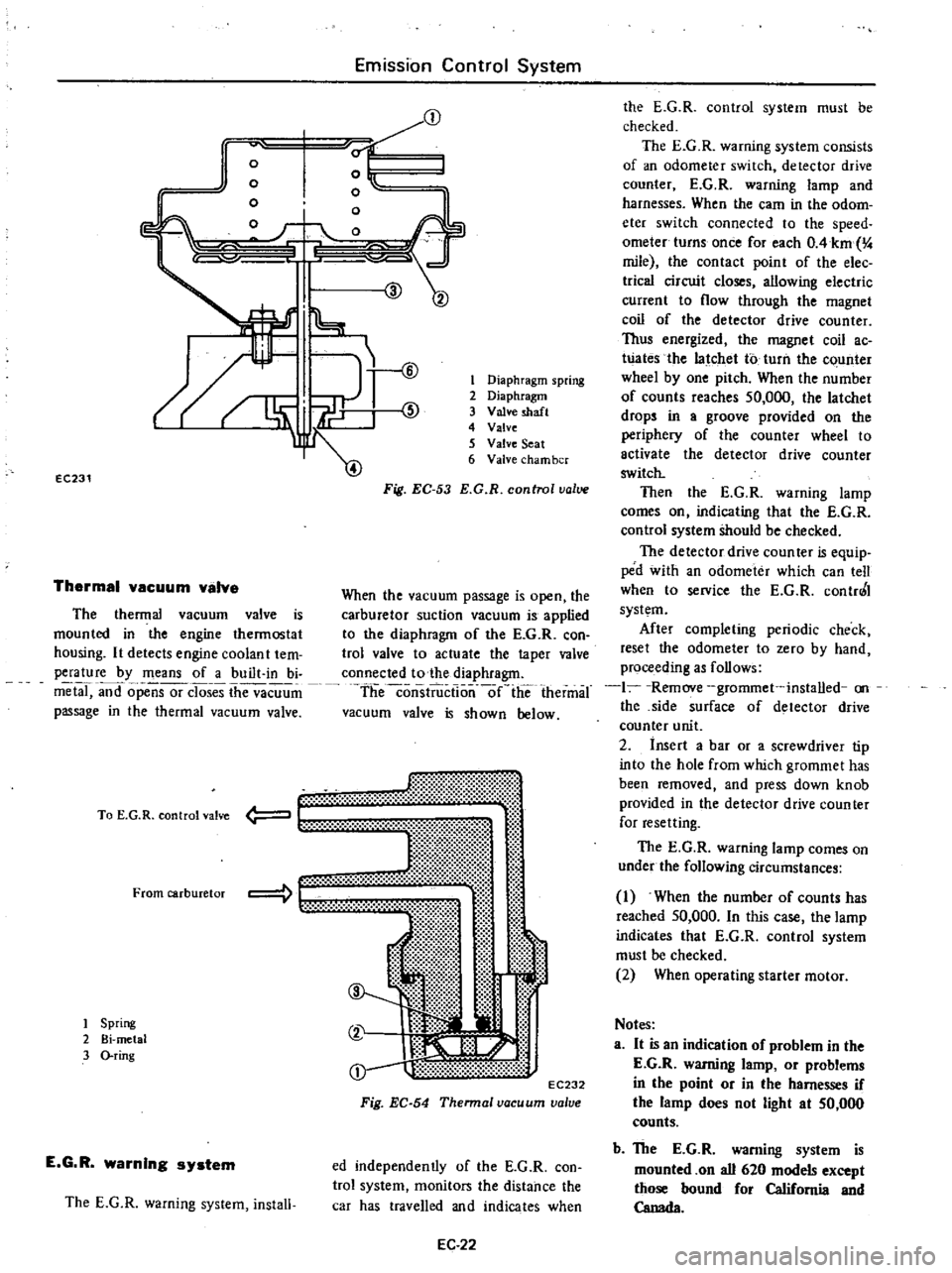
j
EC231
Thermal
vacuum
valva
o
o
m
Emission
Control
System
0
o
o
o
l
l
@
The
thermal
vacuum
valve
is
mounted
in
the
engine
thermostat
housing
It
detects
engine
coolan
t
tem
perature
by
means
of
a
built
in
bi
metal
and
opensor
closes
the
vacuum
passage
in
the
thermal
vacuum
valve
mt
li
t
00
t
EC232
Fig
EC
54
Thennal
vacuum
valve
To
E
G
R
control
valve
From
carburetor
1
Spring
2
Bi
metal
3
O
ring
E
G
R
warning
system
The
E
G
R
warning
system
install
1
Diaphragm
spring
2
Diaphragm
3
Valve
shaft
4
Valve
5
Valve
Seat
6
Valve
cham
ber
Fig
EC
53
E
G
R
control
value
When
the
vacuum
passage
is
open
the
carburetor
suction
vacuum
is
applied
to
the
diaphragm
of
the
E
G
R
con
trol
valve
to
actuate
the
taper
valve
connected
to
the
diaphragm
theconsiiiictlo
nlie
thermal
vacuum
valve
is
shown
below
ed
independently
of
the
E
G
R
con
trol
system
monitors
the
distance
the
car
has
travelled
and
indicates
when
EC
22
the
E
G
R
control
system
must
be
checked
The
E
G
R
warning
system
consists
of
an
odometer
switch
detector
drive
counter
E
G
R
warning
lamp
and
harnesses
When
the
earn
in
the
odom
eter
switch
connected
to
the
speed
ometer
turns
once
for
each
OAkm
4
mile
the
contact
point
of
the
elec
trica
circuit
closes
allowing
electric
current
to
flow
through
the
magnet
coil
of
the
detector
drive
counter
Thus
energized
the
magnet
coil
ac
Wates
the
latchet
to
turn
the
c
unter
wheel
by
one
pitch
When
the
number
of
counts
reaches
50
000
the
latchet
drops
in
a
groove
provided
on
the
periphery
of
the
counter
wheel
to
activate
the
detector
drive
counter
switch
Then
the
E
G
R
warning
lamp
comes
on
indicating
that
the
E
G
R
control
system
Should
be
checked
The
detector
drive
coun
teT
is
equip
ped
with
an
odometer
which
can
tell
when
to
service
the
E
G
R
contr0
I
system
After
completing
periodic
check
reset
the
odometer
to
zero
by
hand
proceeding
as
follows
1
Remove
grommet
installed
on
the
side
surface
of
detector
drive
counter
unit
2
insert
a
bar
or
a
screwdriver
tip
into
the
hole
from
which
grommet
has
been
removed
and
press
down
knob
provided
in
the
detector
drive
counter
for
resetting
The
E
G
R
warning
lamp
comes
on
under
the
following
circumstances
1
When
the
number
of
counts
has
reached
50
000
In
this
case
the
lamp
indicates
that
E
G
R
control
system
must
be
checked
2
When
operating
starter
motor
Notes
a
It
is
an
indication
of
problem
in
the
E
G
R
warning
lamp
or
problems
in
the
point
or
in
the
harnesses
if
the
lamp
does
not
light
at
50
000
counts
b
The
E
G
R
warning
system
is
mounted
on
all
620
models
except
those
bound
for
California
and
Canada
Page 161 of 537
I
Emission
Control
System
Ignition
switch
Ignition
key
Off
T
I
I
I
Battery
I
J
77
77
Relay
J
Floor
temperature
sensing
swi
tch
Floor
temperature
warning
lamp
77
77
EC332
Fig
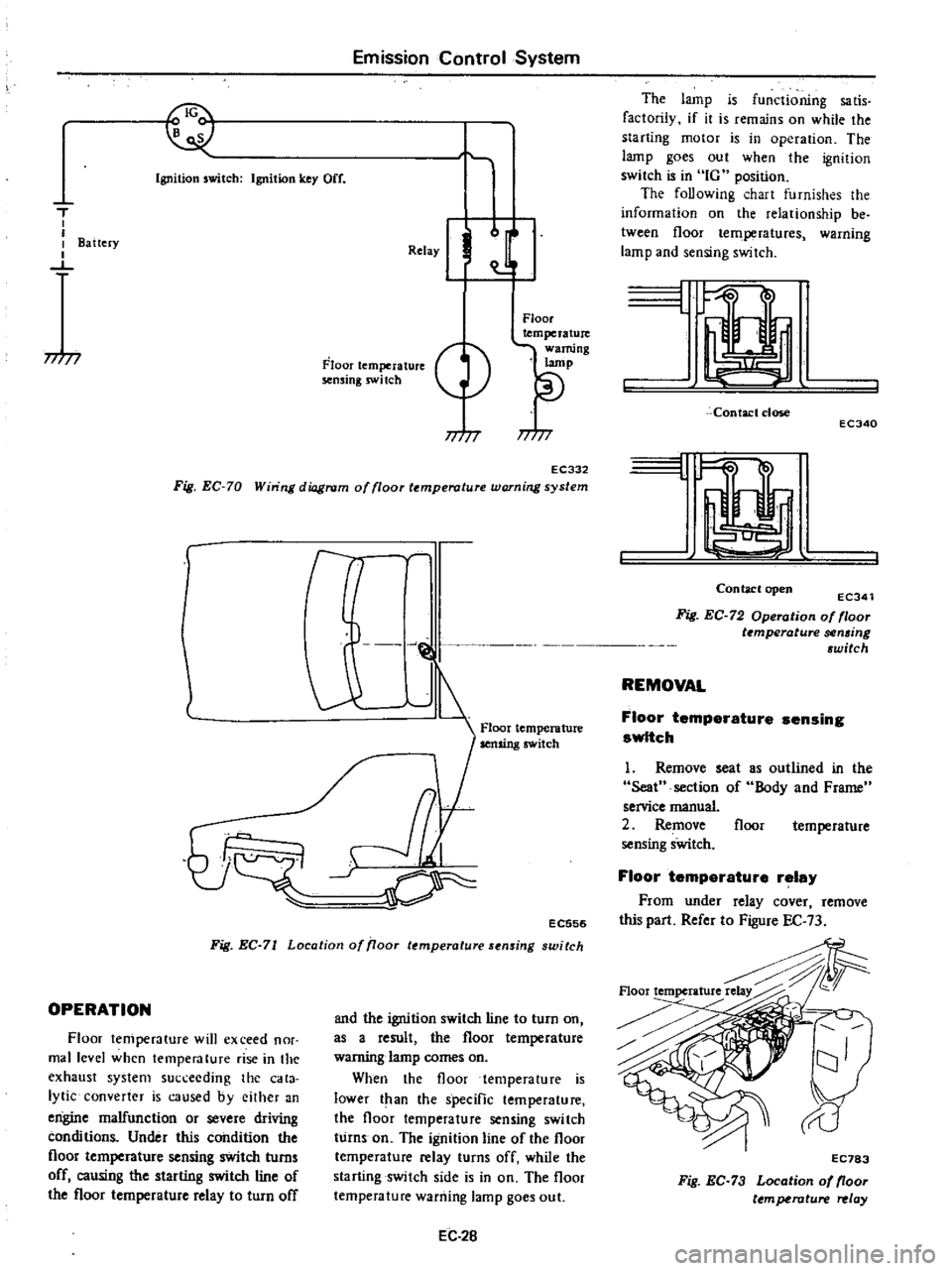
EC
70
Win
ng
diagram
of
floor
temperature
warning
system
r
l
J
@
1
Floor
temperature
Ij
cr
EC556
Fig
EC
71
Location
of
iJoor
temperature
sensing
switch
OPERATION
Floor
temperature
will
exceed
nor
mal
level
when
temperature
rise
in
the
exhaust
system
succeeding
the
cata
lytic
converter
is
caused
byeilher
an
engine
malfunction
or
severe
driving
conditions
Under
this
condition
the
floor
temperature
sensing
switch
turns
off
causing
the
starting
switch
line
of
the
floor
temperature
relay
to
turn
off
and
the
ignition
switch
line
to
turn
on
as
a
result
the
floor
temperature
warning
lamp
comes
on
When
the
floor
temperature
is
lower
t
an
the
specific
temperature
the
floor
temperature
sensing
switch
turns
on
The
ignition
line
of
the
floor
temperature
relay
turns
off
while
the
starting
switch
side
is
in
on
The
floor
temperature
warning
lamp
goes
out
EC
2B
The
lamp
is
functioning
sa
tis
factorily
if
it
is
remains
on
while
the
starting
motor
is
in
operation
The
lamp
goes
out
when
the
ignition
switch
is
in
IG
position
The
foUowing
chart
furnishes
the
information
on
the
relationship
be
tween
floor
temperatures
warning
lamp
and
sensing
switch
L
Contact
close
ECJ40
I
Contaclopen
ECJ41
Fig
EC
72
Operation
of
floor
t
mperature
sen6ing
6witch
REMOVAL
Floor
temperature
sensing
switch
1
Remove
seat
Seat
section
of
service
manual
2
Remove
sensing
sWitch
as
outlined
in
the
Body
and
Frame
floor
temperature
Floor
temperature
relay
From
under
relay
cover
remove
this
part
Refer
to
Figure
EC
73
Floortemperature
EC783
Fig
EC
73
Location
of
floor
ttmperature
relay
Page 166 of 537
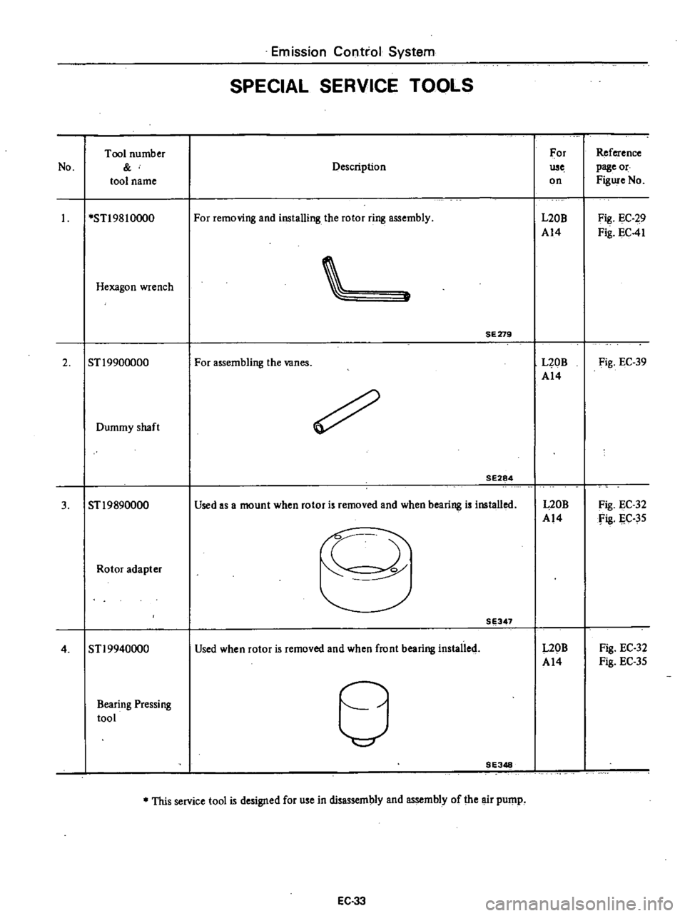
Emission
Control
System
SPECIAL
SERVICE
TOOLS
Tool
number
For
Reference
No
Description
use
page
or
tool
name
on
Figure
No
STI
98
10000
For
removing
and
installing
the
rotor
ring
assembly
L20B
Fig
EC
29
A14
Fig
EC
41
Hexagon
wrench
SE279
2
ST
19900000
For
assembling
the
vanes
L20B
Fig
EC
39
A14
Dummy
shaft
SE284
3
STl9890000
Used
as
a
mount
when
rotor
is
removed
and
when
bearing
is
installed
L20B
Fig
EC
32
A14
fig
IlC
35
f
Rotor
adapter
SE347
4
STl9940000
Used
when
rotor
is
removed
and
when
front
bearing
installed
L20B
Fig
EC
32
A14
Fig
EC
35
Bearing
Pressing
tool
d
9E348
This
service
tool
is
designed
for
use
in
disassembly
and
assembly
of
the
air
pump
EC
33
Page 171 of 537

DESCRIPTION
OPERATION
CONSTR
UCTI
ON
REMOVAL
DISASSEMBL
Y
CLEANING
AND
INSPECTION
TERMINAL
FIELD
COIL
BRUSHES
AND
BRUSH
LEAD
WIRE
BRUSH
SPRING
TENSION
ARMATURE
ASSEMBLY
DESCRIPTION
The
function
of
the
starting
system
which
consists
of
the
battery
ignition
switch
starting
motor
and
solenoid
is
to
crank
the
engine
The
electrical
energy
is
supplied
from
the
battery
the
solenoid
completes
the
circuit
to
operate
the
starling
motor
and
then
the
motor
carries
out
the
actual
crank
ing
of
the
engine
Engine
Electrical
System
STARTING
MOTOR
CONTENTS
EE
4
EE
6
EE
7
EE
7
EE
7
EE
8
EE
8
EE
B
EE
B
EE
B
EE
B
OVERRUNNING
CLUTCH
ASSEMBLY
BRUSH
HOLDER
TEST
FOR
GROUND
BEARING
METAL
MAGNETIC
SWITCH
ASSEMBLY
ASSEMBLY
TEST
PERFORMANCE
TEST
MAGNETIC
SWITCH
ASSEMBLY
TEST
SERVICE
DATA
AND
SPECIFICATIONS
TROUBLE
DIAGNOSES
AND
CORRECTIONS
5
@
EE
9
EE
9
EE
9
EE
9
EE
9
EE
9
EE
9
EE
O
EE
EE
11
I
Brush
2
Field
coil
3
Magnetic
switch
4
Pludgcr
5
Torsion
spring
6
Shifll
r
7
Overrunning
clutch
8
Pinion
9
Armature
9
EE315
Fig
EE
5
Sectioool
view
of
slarting
motor
Sl14
180B
EE
4
Page 178 of 537

Engine
Electrical
System
SERVICE
DATA
AND
SPECIFICATIONS
Type
System
voltage
No
load
Terminal
voltage
Current
Revolution
v
V
A
rpm
Brush
length
Outer
diameter
of
commutator
mm
in
mm
in
Brush
spring
tension
kg
Ib
Clearance
between
bearing
metal
and
armature
shaft
mm
in
Clearance
L
between
pinion
front
edge
and
pinion
stopper
mm
in
TROUBLE
DIAGNOSES
AND
CORRECTIONS
Condition
Starting
motor
will
not
operate
Noisy
starting
motor
Starting
motor
cranks
slowly
Probable
cause
Discharged
battery
Damaged
solenoid
switch
Loose
connections
of
terminal
Damaged
brushes
Starti
g
motor
inoperative
Loose
securing
bolt
Worn
pinion
gear
Poor
lubrication
Worn
commutator
Worn
brushes
Discharged
battery
Loose
connection
of
terminal
Worn
brushes
Locked
brushes
EE
ll
Manual
transmission
Automatic
transmission
Optional
for
manual
transmission
SII4
ISOB
S114
170B
12
12
Less
than
60
More
than
7
000
More
than
6
000
More
than
39
1
54
More
than
12
0
47
1
4
to
I
S
3
1
to
4
0
Less
than
0
2
O
OOS
0
3
to
1
5
0
012
to
0
059
Corrective
action
Charge
or
replace
battery
Repair
or
replace
solenoid
switch
Clean
and
tighten
terminal
Replace
brushes
Remove
starting
motor
and
make
test
Tighten
Replace
Add
oil
Replace
Replace
Charge
Clean
and
tighten
Replace
Inspect
brush
spring
tension
or
repair
brush
holder