ECU DATSUN PICK-UP 1977 Manual Online
[x] Cancel search | Manufacturer: DATSUN, Model Year: 1977, Model line: PICK-UP, Model: DATSUN PICK-UP 1977Pages: 537, PDF Size: 35.48 MB
Page 424 of 537

Engine
Control
Fuel
Exhaust
Systems
I
Wipe
clean
all
the
contact
por
tions
of
tube
joints
allow
them
to
dry
thoroughly
2
Temporarily
mount
in
place
muffler
assembly
as
an
assembled
unit
on
the
vehicle
3
Insert
front
tube
until
it
touches
emboss
m
b
nlfrnnjj
mm
lJ
Ij
@L
J
FE263
Fig
FE
ll
Exhawt
tube
connection
4
Torque
nut
securing
the
male
and
female
tubes
at
the
connection
Tightening
torque
is
1
6
to
2
0
kg
m
12
to
14
ft
lb
5
Squeeze
approximately
5
CC
0
31
cu
in
of
sealant
into
injection
from
sealant
tube
See
Figure
FE
12
Sealant
tube
polyethylene
Injector
Fig
FE
IO
Exhaust
sealant
kit
Be
sure
to
place
cap
back
to
sealant
tube
since
sealant
will
dry
Approximately
5
cc
0
31
Cll
in
FE1l1
Fig
FE
12
Squeezing
sealant
to
injec
tor
6
Position
nozzle
of
injector
to
the
guide
and
press
it
there
firmly
Inject
sealant
slowly
until
sealant
begins
to
flow
out
of
the
slit
of
tube
This
indicates
that
the
bead
requires
no
further
sealant
Excessive
sealant
can
cause
a
clogged
tube
See
Figure
FE
13
After
injecting
wash
injector
thoroughly
in
clean
water
to
remove
all
traces
of
sealant
FE191
Fig
FE
13
Injecting
sealant
FE
9
7
Start
engine
and
let
it
idle
slowly
for
ten
minutes
minimum
to
hilfden
sealant
with
the
heat
of
exhaust
gas
8
Check
the
condition
of
sealant
before
driving
the
vehicle
It
is
also
essential
that
the
vehicle
should
not
be
accelerated
sharply
for
20
to
30
minutes
subsequent
to
this
operation
Noles
a
The
sealant
should
be
used
within
guaranty
term
indicated
on
the
kit
case
b
Exposure
of
sealant
to
the
skin
may
cause
a
rash
Wash
sealant
off
the
skin
with
water
c
Do
not
keep
the
sealant
tube
in
a
place
where
the
ambient
tempera
ture
is
above
400C
I040F
A
sealant
hardened
above
4QoC
I040F
cannot
be
used
The
most
suitable
storage
temperature
is
from
15
to
350C
59
to
950F
If
sealant
becomes
hardened
because
of
low
temperatures
wann
the
sealant
tube
with
lukewarm
water
until
the
sealant
is
softened
Do
not
warm
tube
at
a
temperature
over
400C
1040F
for
a
long
time
d
Thoroughly
read
the
instruction
sheet
furnished
with
the
kit
before
using
the
sealant
i
Page 428 of 537
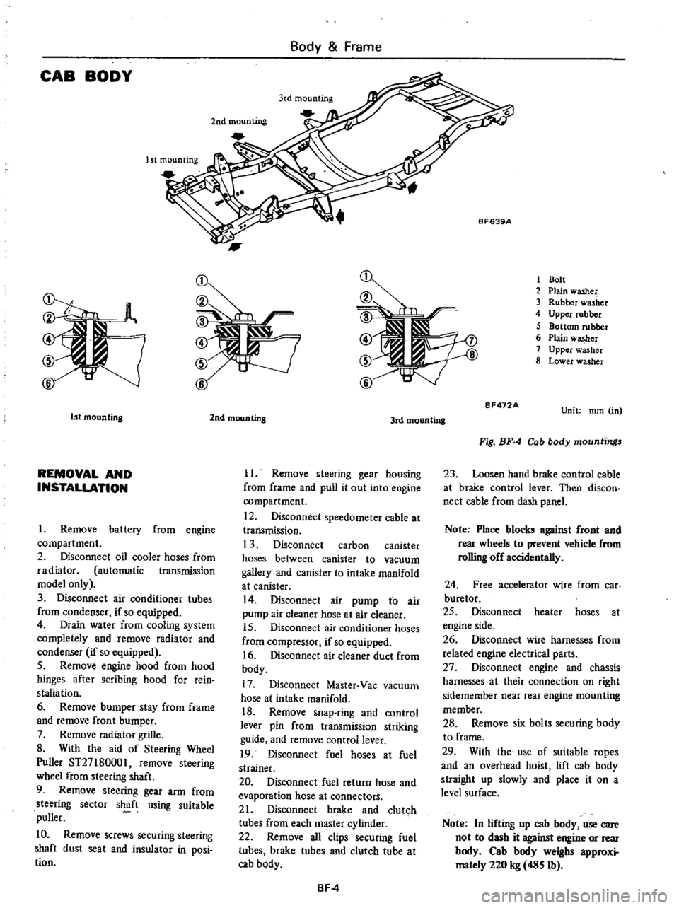
CAB
BODY
Body
Frame
Ist
mounting
2nd
mounting
1
Bolt
2
Plain
washer
3
Rubber
washer
4
Upper
rubber
5
Bottom
rubber
6
Plain
w
er
7
Upper
washer
8
Lower
washer
1st
mounting
REMOVAL
AND
INSTALLATION
Remove
battery
from
engine
compartment
2
Disconnect
oil
cooler
hoses
from
radiator
automatic
transmission
model
only
3
Disconnect
air
conditioner
tubes
from
condenser
if
so
equipped
4
Drain
water
from
cooling
system
completely
and
remove
radiator
and
condenser
if
so
equipped
5
Remove
engine
hood
from
hood
hinges
after
scribing
hood
for
rein
stallation
6
Remove
bumper
stay
from
frame
and
remove
front
bumper
7
Remove
radiator
grille
8
With
the
aid
of
Steering
Wheel
Puller
ST27
180001
remove
steering
wheel
from
steering
shaft
9
Remove
steering
gear
arm
from
steering
sector
shaft
using
suitable
puller
10
Remove
screws
securing
steering
shaft
dust
seat
and
insulator
in
posi
tion
2nd
mounting
3rd
mounting
II
Remove
steering
gear
housing
from
frame
and
pull
it
out
into
engine
compartment
12
Disconnect
speedometer
cable
at
transmission
1
3
Disconnect
carbon
canister
hoses
between
canister
to
vacuum
gallery
and
canister
to
intake
manifold
at
canister
14
Disconnect
air
pump
to
air
pump
air
cleaner
hose
at
air
cleaner
15
Disconnect
air
conditioner
hoses
from
compressor
if
so
equipped
16
Disconnect
air
cleaner
duct
from
body
17
Disconnect
Master
Vac
vacuum
hose
at
intake
manifold
18
Remove
snap
ring
and
control
lever
pin
from
transmission
striking
guide
and
remove
control
lever
19
Disconnect
fuel
hoses
at
fuel
strainer
20
Disconnect
fuel
return
hose
and
evaporation
hose
at
connectors
21
Disconnect
brake
and
clutch
tubes
from
each
master
cylinder
22
Remove
all
clips
securing
fuel
tubes
brake
tubes
and
clutch
tube
at
cab
body
BF
4
BF472A
Unit
mm
in
Fig
BF
4
Cab
body
mountings
23
Loosen
hand
brake
control
cable
at
brake
control
lever
Then
discon
nect
cable
from
dash
panel
Note
Place
blocks
against
front
and
rear
wheels
to
prevent
vehicle
from
rolling
off
accidentally
24
Free
accelerator
wire
from
car
buretor
25
Disconnect
heater
hoses
at
engine
side
26
Disconnect
wire
harnesses
from
related
engine
electrical
parts
27
Disconnect
engine
and
chassis
harnesses
at
their
connection
on
right
sidemember
near
rear
engine
mounting
member
28
Remove
six
bolts
securing
body
to
frame
29
With
the
use
of
suitable
ropes
and
an
overhead
hoist
lift
cab
body
straight
up
slowly
and
place
it
on
a
level
surface
Note
In
lifting
up
cab
body
use
care
not
to
dash
it
against
engine
or
rear
body
Cab
body
weighs
approxi
mately
220
kg
485
Ib
Page 429 of 537
Body
Frame
30
For
installation
reverse
above
steps
However
observe
the
following
instructions
i
If
the
cab
body
is
to
be
replaced
note
position
and
location
of
insula
tors
and
washers
used
See
Figure
BF
4
2
Adjust
hand
brake
stroke
pro
perly
3
Air
bleed
brake
and
clutch
system
thorougWy
Cab
body
to
frame
mounting
bolt
torque
1
6
to
2
2
kg
m
12
to
16
ft
Ib
o
i
k
q
1Q
j
b
crru
V
J
8F630
rr
1
4
n
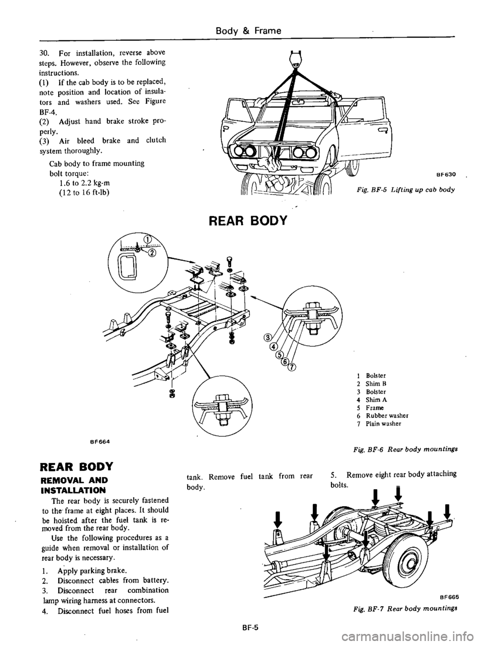
Fig
BF
5
Lifting
up
cab
body
REAR
BODY
1
Bolster
2
Shim
B
3
Bolster
4
Shim
A
5
Frame
6
Rubber
washer
7
Plain
washer
BF664
Fig
BF
6
Rear
body
mountings
REAR
BODY
REMOVAL
AND
INSTALLATION
The
rear
body
is
securely
fastened
to
the
frame
at
eight
places
It
should
be
hoisted
after
the
fuel
tank
is
re
moved
from
the
rear
body
Use
the
following
procedures
as
a
guide
when
removal
or
installation
of
rear
body
is
necessary
I
Apply
parking
brake
2
Disconnect
cables
from
battery
3
Disconnect
rear
combination
lamp
wiring
harness
at
connectors
4
Disconnect
fuel
hoses
from
fuel
tank
Remove
fuel
tank
from
rear
body
5
Remove
eight
rear
body
attaching
bolts
BF665
Fig
BF
7
Rear
body
mountings
BF
5
Page 432 of 537
COWL
TOP
GRILLE
@
@
REMOVAL
AND
INSTALLATION
I
Open
engine
hood
2
Remove
two
windshield
wiper
blad
3
Remove
cowl
top
grille
attaching
HOOD
REMOVAL
AND
INSTALLATION
1
Place
protective
covers
over
front
fender
and
cowl
top
grille
2
Open
engine
hood
Mark
hinge
locations
on
hood
and
loosen
off
four
bolts
securing
hood
to
hood
hinge
Use
extra
caution
to
avoid
damaging
painted
surfaces
of
fender
and
cowl
top
grille
3
Remove
engine
hood
4
To
install
reverse
above
pro
cedures
ADJUSTMENT
Four
slotted
holes
in
hood
hinge
provide
for
fore
aft
and
side
adjust
ment
to
correct
space
between
hood
and
fender
and
hood
and
cowl
top
grille
Loosen
four
bolts
just
enough
to
move
engine
hood
and
move
hood
to
desired
position
if
necessary
to
correct
space
To
make
vertical
adjustment
adjust
height
of
dove
tail
bolt
at
hood
lock
male
until
hood
is
flush
with
fender
Body
Frame
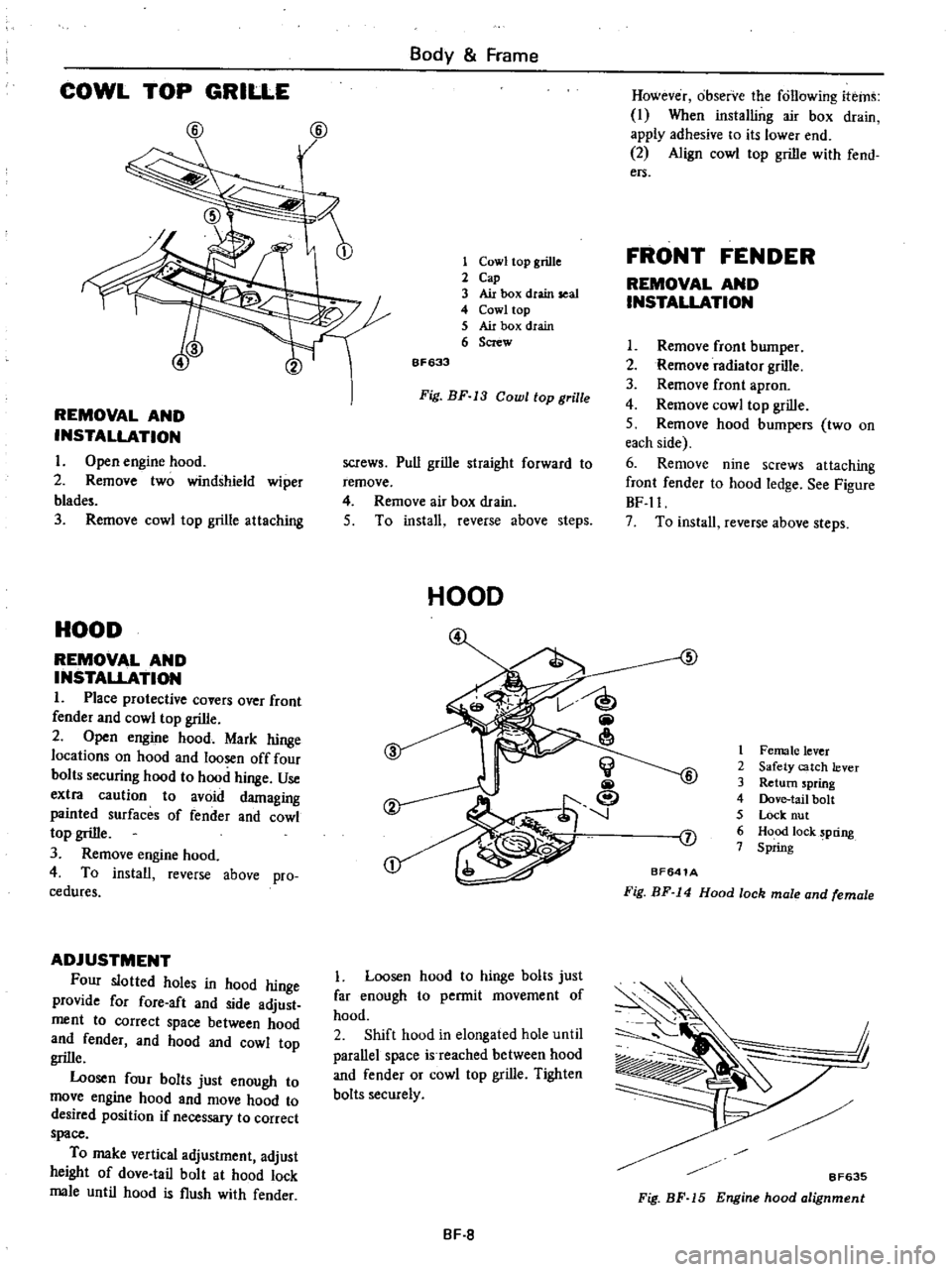
1
Cowl
top
grille
2
Cap
3
Air
box
dtain
seal
4
Cowl
top
5
Air
box
drain
6
Screw
6F633
Fig
BF
13
Cowl
top
grille
screws
Pull
grille
straight
forward
to
remove
4
Remove
air
box
drain
5
To
install
reverse
above
steps
HOOD
Loosen
hood
to
hinge
bolts
just
far
enough
to
permit
movement
of
hood
2
Shift
hood
in
elongated
hole
until
parallel
space
is
reached
between
hood
and
fender
or
cowl
top
grille
Tighten
bolts
securely
BF
8
However
observe
the
following
items
I
When
installing
air
box
drain
apply
adhesive
to
its
lower
end
2
Align
cowl
top
grille
with
fend
ers
FRONT
FENDER
REMOVAL
AND
INSTALLATION
I
Remove
front
bumper
2
Remove
radiator
grille
3
Remove
front
apron
4
Remove
cowl
top
grille
S
Remove
hood
bumpers
two
on
each
side
6
Remove
nine
screws
attaching
front
fender
to
hood
ledge
See
Figure
BF
ll
7
To
install
reverse
above
steps
5
1
Female
lever
2
Safety
catch
lever
3
Return
spring
4
Dove
tail
bolt
S
Lock
nut
6
Hood
lock
pring
7
Spring
J
BF641A
Fig
BF
14
Hood
lock
male
and
female
j
I
8F635
Fig
BF
15
Engine
hood
alignment
Page 433 of 537
Body
Frame
Note
Vertical
adjustment
should
be
carried
out
after
hood
lock
male
and
female
adjustment
has
been
completed
3
To
correct
hood
lock
alignment
loosen
two
hood
lock
male
attaching
bolts
and
move
hood
lock
male
and
female
in
the
lateral
and
fore
and
aft
directions
as
required
D
1r
r
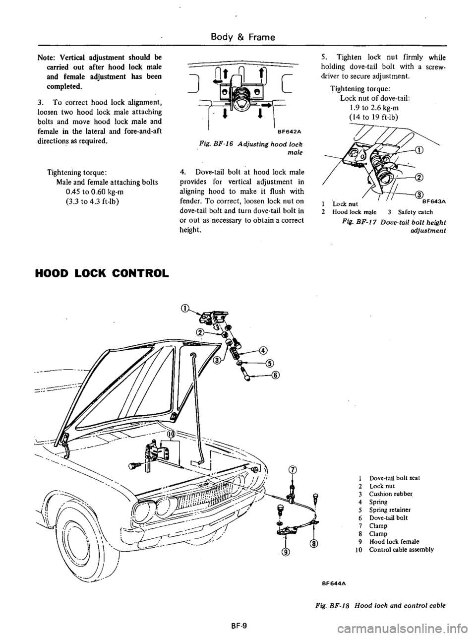
BF642A
Fig
BF
16
Adjusting
hood
lock
male
Tightening
torque
Male
and
female
attaching
bolts
0
45
to
0
60
kg
m
3
3
to
4
3
ft
Ib
4
Dove
tail
bolt
at
hood
lock
male
provides
for
vertical
adjustment
in
aligning
hood
to
make
it
flush
with
fender
To
correct
loosen
lock
nut
on
dove
tail
bolt
and
turn
dove
tail
bolt
in
or
out
as
necessary
to
obtain
a
correct
height
HOOD
LOCK
CONTROL
JI
I
i
I
r
lPP
J
jJ
J
Sr
aj
I
I
I
J
f
ifry
ff
I
ii1iiilliii
j
iW
r
U
I
j
Y
f
7
j
1
JJ
J
8F
9
5
Tighten
lock
nut
firmly
while
holding
dove
tail
bolt
with
a
screw
driver
to
secure
adjustment
Tightening
torque
Lock
nut
of
dove
tail
1
9
to
2
6
kg
m
14
to
19
ft
lb
BF643A
1
Lock
nut
2
Hood
lock
male
3
Safety
catch
Fig
BF
17
Doue
tail
bolt
height
adjustment
1
Dove
tail
bolt
seat
2
Lock
nut
3
Cushion
rubber
4
Spring
5
Spring
retainer
6
Dove
tail
bolt
7
Clamp
8
Clamp
9
Hood
lock
female
10
Control
cable
assembly
BF644A
Fig
BF
18
Hood
lock
and
control
cable
Page 434 of 537
REMOVAL
AND
INSTALLATION
I
Remove
hood
lock
male
by
re
moving
two
attaching
bolts
2
To
remove
hood
lock
female
first
remove
radiator
grille
Back
off
two
bolts
securing
hood
lock
female
in
position
Hood
lock
female
can
now
be
taken
out
3
Remove
two
bolts
attaching
hood
lock
handle
assembly
to
dash
side
paneL
Disconnect
cable
at
hood
lock
female
and
remove
cable
clamps
Pull
cable
out
into
cab
4
To
install
hood
lock
male
and
female
reverse
removal
procedure
Mter
installation
check
to
insure
that
they
are
properly
aligned
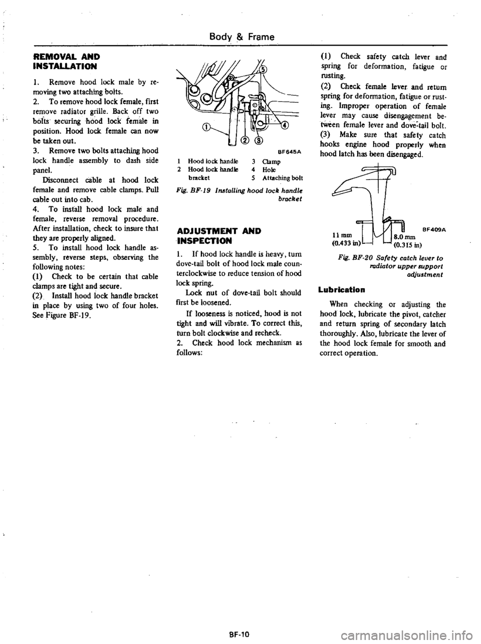
5
To
install
hood
lock
handle
as
sembly
reverse
steps
observing
the
following
notes
I
Check
to
be
certain
that
cable
clamps
are
tight
and
secure
2
Install
hood
lock
handle
bracket
in
place
by
using
two
of
four
holes
See
Figure
BF
19
Body
Frame
@
1
Hood
tock
handle
2
Hood
lock
handle
bracket
BF645A
3
Clamp
4
Hole
5
Attaching
bolt
Fig
BF
19
1MtalIing
hood
lock
handle
brocket
ADJUSTMENT
AND
INSPECTION
I
If
hood
lock
handle
is
heavy
turn
dove
tail
bolt
of
hood
lock
male
coun
terclockwise
to
reduce
tension
of
hood
lock
spring
Lock
nut
of
dove
tail
bolt
should
fust
be
loosened
If
looseness
is
noticed
hood
is
not
tight
and
will
vibrate
To
correct
this
turn
bolt
clockwise
and
recheck
2
Check
hood
lock
mechanism
as
follows
BF
10
I
Check
safety
catch
lever
and
spring
for
deformation
fatigue
or
rusting
2
Check
female
lever
and
return
spring
for
deformation
fatigue
or
rust
ing
Improper
operation
of
female
lever
may
cause
disengagement
be
tween
female
lever
and
dove
tail
bolt
3
Make
sure
that
safety
catch
hooks
engine
hood
properly
when
hood
latch
has
been
disengaged
0l
11
mm
I
nun
BF409A
0
433
in
0
3t5
in
Fig
BF
20
Safety
catch
lever
to
radiator
upper
support
acVu5tment
Lubrication
When
checking
or
adjusting
the
hood
lock
lubricate
the
pivot
catcher
and
return
spring
of
secondary
latch
thoroughly
Also
lubricate
the
lever
of
the
hood
lock
female
for
smooth
and
correct
operation
Page 436 of 537

@
I
r
L
c
@
DESCRIPTION
The
door
consists
of
inner
and
outer
panels
welded
together
to
form
a
rigid
structure
The
curved
glass
provides
greater
shoulder
room
A
door
that
incorporates
a
ventila
tor
window
is
also
available
as
an
option
The
weatherstrip
is
inserted
into
the
groove
on
the
door
sash
side
and
is
attached
by
clips
on
the
door
side
DOOR
REMOVAL
AND
INSTALLATION
I
With
door
in
full
open
position
place
a
garage
jack
or
stand
beneath
door
to
support
its
weight
when
bolts
are
removed
Place
rag
between
door
and
jack
or
stand
to
avoid
damaging
painted
surface
Body
Frame
CD
1
@
@
ID
@
AJ
@
@
@
1
Door
sash
2
Window
outside
weatherstrip
3
Window
inside
weatherstrip
4
Door
atherstrip
5
Rear
glass
run
rubber
6
Door
finish
holder
7
Rear
lower
sash
8
Seal
screen
9
Door
weatherstrip
clip
10
Front
glass
run
rubber
11
Lower
door
hinge
12
Upper
door
hinge
13
Front
lower
sash
14
Door
glass
15
Glazing
rubber
16
Door
glass
bottom
channel
11
Lower
support
18
Upper
support
19
Door
ventilator
assembly
BF031B
Fig
BF
22
Door
with
ntilator
window
Optional
BF023
Fig
BF
23
Supporting
door
2
Separate
lower
door
hinge
hole
cover
from
dash
side
trim
3
While
supporting
door
as
above
back
off
body
to
upper
and
lower
hinge
attaching
bolts
accessible
from
inside
cab
three
each
Door
can
now
be
taken
out
from
cab
body
I
t
I
l
f
p1
1
W
JJ
i
Sl
j
Fig
BF
24
Removing
door
hinge
bolt
8F
12
4
To
install
reverse
removal
pro
cedure
ALIGNMENT
Elongated
holes
three
each
in
door
hinge
and
door
lock
striker
pro
vide
for
up
and
down
forward
and
backward
and
or
sideways
adjustment
to
assure
proper
door
fit
to
door
opening
To
adjust
door
alignment
loosen
bolts
and
move
door
to
desired
posi
lion
to
obtain
a
parallel
space
between
door
sides
and
door
opening
Also
check
to
be
certain
that
weatherstrip
contacts
body
opening
evenly
to
pre
vent
entry
of
mud
and
water
DOOR
TRIM
AND
SEAL
REMOVAL
AND
INSTALLATION
1
Remove
screw
securing
inside
door
handle
escutcheon
remove
es
cutcheon
2
Remove
screws
which
hold
pull
handle
and
arm
rest
in
position
Pull
handle
and
arm
rest
can
then
be
taken
out
3
Pull
retaining
spring
off
regulator
handle
Take
out
regulator
handle
and
seat
washer
Page 437 of 537

BF640
4
When
removing
door
finish
it
is
important
that
inside
door
panel
and
door
finish
are
not
damaged
With
a
screwdriver
pry
off
re
taining
clips
exercising
care
not
to
damage
clips
I
a
I
II
I
L
jl
ld
II
Fig
BF
26
Removing
door
finish
5
Separate
water
seal
screen
from
inside
door
panel
6
To
install
reverse
removal
pro
cedure
However
observe
the
follow
ing
instalJation
notes
i
When
water
seal
screen
is
to
be
replaced
be
Sure
to
cement
it
back
into
position
securely
to
ensure
a
water
sealed
door
This
can
be
done
by
evenly
applying
adhesive
to
grooves
in
inside
door
panel
Broken
screen
Or
one
suspected
to
be
leaking
must
be
replaced
with
a
new
one
Body
Frame
1
3
Seat
washer
Regulator
handle
Retaining
spring
Fig
BF
25
Removing
regulator
handle
Adhesive
I
i
f
f
nil
Section
A
A
Ii
ir
coil
IIIII
I
J
J
iif
J
lUJ
A
A
J
J
BF641
Fig
BF
27
Adhesive
for
seal
screen
2
With
door
glass
up
set
regulator
handle
at
an
angle
shown
in
Figure
BF
28
d
1
J
900
Spring
l
BF462
Fig
BF
28
Installation
angle
of
regulator
handle
GLASS
RUN
REMOVAL
AND
INSTALLATION
I
With
door
in
full
out
position
lower
glass
all
the
way
2
Remove
pull
handle
arm
rest
and
regulator
handle
3
Remove
door
fmish
and
water
seal
screen
4
Remove
outer
and
inner
weather
strips
from
door
BF
13
5
Remove
door
glass
6
Remove
glass
run
rubbers
from
front
and
rear
lower
sashes
and
from
those
of
fixed
door
Use
caution
to
avoid
damaging
rubbers
during
removal
operation
7
Remove
front
and
rear
lower
door
sashes
when
ventilator
window
is
not
provided
8
On
vehicles
equipped
with
venti
lator
window
remove
ventilator
window
frame
and
rear
lower
door
sash
9
To
install
reverse
removal
pro
cedure
However
observe
the
follow
ing
notes
I
Before
applying
adhesive
clean
the
inside
of
door
sash
2
Apply
adhesive
to
glass
run
rubber
on
door
sash
contacting
face
and
fit
it
correctly
Particularly
care
should
be
taken
at
corners
and
contact
face
to
assure
a
good
fit
CD
CID
BF641
1
Door
sash
2
Glass
run
rubber
3
Adhesive
Fig
BF
29
Applying
adhesive
to
glass
run
ru
bber
DOOR
VENTILATOR
WINDOW
Optional
REMOVAL
AND
INSTALLATION
I
Remove
five
ventilator
window
frame
attaching
bolts
Lift
frame
out
of
door
For
detailed
procedure
refer
to
relative
topic
under
Door
Glass
and
Regulator
2
Remove
nuts
and
spring
securing
lower
end
of
ventilator
window
to
frame
3
Work
off
rivets
which
hold
upper
end
of
ventilator
window
to
frame
take
out
window
4
To
install
reverse
removal
pro
cedure
Page 438 of 537

Body
Frame
DOOR
GLASS
AND
REGULATOR
CD
REMOVAL
AND
INSTALLATION
L
Open
door
lower
glass
all
the
way
2
Remove
iflllide
door
handle
es
cutcheon
3
Remove
pull
handle
4
Remove
arm
rest
5
Remove
regulator
handle
6
Remove
door
finish
7
Peel
off
water
seal
screen
8
Work
off
outer
and
inner
weath
erstrips
from
door
being
sure
not
to
scratch
door
paint
during
operation
Use
a
suitable
plain
screwdriver
or
similar
flat
bladed
tool
io
remove
and
place
a
piece
of
rag
between
screw
driver
and
door
panel
BF643
1
Outet
weatherstrip
2
Screwdriver
3
Piece
of
rag
Fig
BF
31
Removing
outer
weather
trip
9
Remove
three
door
glass
bottom
channel
attaching
bolts
Remove
door
glass
by
lifting
it
straight
up
Fig
BF
30
Door
gl
and
regulator
10
On
door
equipped
with
venti
lator
remove
three
bolts
securing
door
glass
bottom
channel
then
let
glass
go
to
the
bottom
of
door
Remove
ventilator
frame
attaching
bolts
and
lift
frame
straight
up
out
of
door
Remove
door
glass
by
lifting
it
straight
up
11
Back
off
the
five
guide
channel
to
regulator
base
attaching
screws
Take
out
regulator
assembly
through
large
access
hole
in
inside
door
panel
DOOR
LOCK
1
Escutcheon
2
Inside
handle
3
Spring
4
Door
lock
knob
5
Knob
grommet
6
Outside
handle
7
Outside
handle
rod
j
f
ffi
I
Fig
BF
32
BF035
Removing
door
glass
12
To
install
reverse
removal
pro
cedure
ADJUSTMENT
I
In
and
out
and
fore
and
aft
ad
justment
can
be
made
by
moving
front
or
rear
sash
and
guide
channel
as
required
The
ease
with
which
window
assem
bly
raises
and
lowers
depends
on
ad
justment
of
rear
lower
sash
Rear
lower
sash
should
be
parallel
with
front
lower
sash
2
Fore
and
aft
adjustment
is
deter
mined
by
position
of
guide
channel
and
front
lower
sash
Moving
front
lower
sash
backward
reduces
play
in
window
assembly
j
CID
@
8
Nylon
nut
9
Locking
plate
ring
10
LOcking
plate
11
Door
lock
cylinder
12
Door
lock
13
Stopper
BF
14
BF410A
Fig
BF
33
Door
lock
mechonillm
Page 442 of 537
Body
Frame
INTERIOR
TRIM
AND
CENTER
CONSOLE
HEADLINING
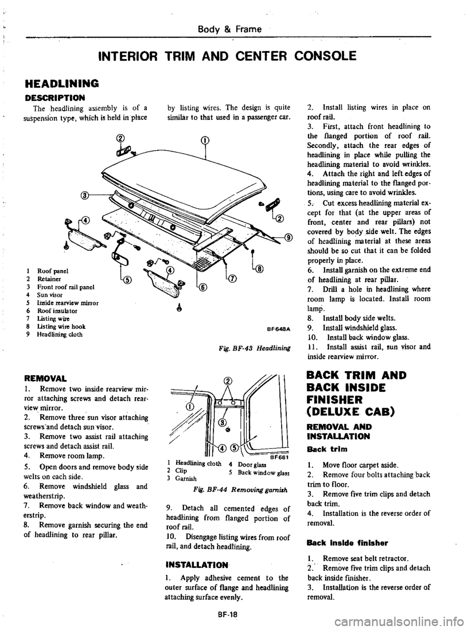
DESCRIPTION
The
headlining
assembly
is
of
a
suspension
type
which
is
held
in
place
ct
I
2
3
4
5
6
7
8
9
REMOVAL
1
Remove
two
inside
rearview
mir
ror
attaching
screws
and
detach
rear
view
mirror
2
Remove
three
sun
visor
attaching
screws
and
detach
sun
visor
3
Remove
two
assist
rail
attaching
screws
and
detach
assist
rail
4
Remove
room
lamp
5
Open
doors
and
remove
body
side
welts
on
each
side
6
Remove
windshield
glass
and
weatherstrip
7
Remove
back
window
and
weath
erstrip
8
Remove
garnish
securing
the
end
of
headlining
to
rear
pillar
by
listing
wires
The
design
is
quite
similar
to
that
used
in
a
passenger
car
A
BF648A
Fig
BF
43
Headlining
CD
r
h
i
r
J
I
I
I
II
CID
BF661
1
Headlining
cloth
4
Door
glass
2
Clip
5
Back
window
glass
3
Garnish
Fig
BF
44
Removing
gami8h
9
Detach
all
cemented
edges
of
headlining
from
flanged
portion
of
roof
rail
10
Disengage
listing
wires
from
roof
rail
and
detach
headlining
INSTALLATION
I
Apply
adhesive
cement
to
the
outer
surface
of
flange
and
headlining
attaching
surface
evenly
8F
18
2
Install
listing
wires
in
place
on
roof
rail
3
First
attach
front
headlining
to
the
flanged
portion
of
roof
rail
Secondly
attach
the
rear
edges
of
headlining
in
place
while
pulling
the
headlining
material
to
avoid
wrinkles
4
Attach
the
right
and
left
edges
of
headlining
material
to
the
flanged
por
tions
using
care
to
avoid
wrinkles
5
Cut
excess
headlining
material
ex
cept
for
that
at
the
upper
areas
of
front
center
and
rear
pillars
not
covered
by
body
side
welt
The
edges
of
headlining
ma
terial
at
these
areas
should
be
so
cut
that
it
can
be
folded
properly
in
place
6
Install
garnish
on
the
extreme
end
of
headlining
at
rear
pillar
7
Drill
a
hole
in
headlining
where
room
lamp
is
located
Install
room
lamp
8
Install
body
side
welts
9
Install
windshield
glass
10
Install
back
window
glass
11
Install
assist
rail
sun
visor
and
inside
rearview
mirror
BACK
TRIM
AND
BACK
INSIDE
FINISHER
DELUXE
CAB
REMOVAL
AND
INSTALLATION
Back
trim
I
Move
floor
carpet
aside
2
Remove
four
bolts
attaching
back
trim
to
floor
3
Remove
five
trim
clips
and
detach
back
trim
4
Installation
is
the
reverse
order
of
removal
Back
Inside
finisher
I
Remove
seat
belt
retractor
2
Remove
five
trim
clips
and
detach
back
inside
fmisher
3
Installation
is
the
reverse
order
of
removal