DODGE CHARGER 2015 7.G User Guide
Manufacturer: DODGE, Model Year: 2015, Model line: CHARGER, Model: DODGE CHARGER 2015 7.GPages: 236, PDF Size: 35.67 MB
Page 151 of 236
Programming A Rolling Code
NOTE:
For programming Garage Door Openers that were manufactured after 1995. These Garage
Door Openers can be identified by the “LEARN” or “TRAIN” button located where the
hanging antenna is attached to the Garage Door Opener. It is NOT the button that is
normally used to open and close the door. The name and color of the button may vary by
manufacturer.
1. Place the ignition switch into the ON/RUN position.
2. Place the hand-held transmitter 1 to 3 inches (3 to 8 cm) away from the HomeLink®
button you wish to program while keeping the HomeLink®indicator light in view.
3. Push and hold the HomeLink®button you want to program while you push and hold
the hand-held transmitter button.
4. Continue to hold both buttons and observe the indicator light. The HomeLink®
indicator will flash slowly and then rapidly after HomeLink®has received the fre-
quency signal from the hand-held transmitter. Release both buttons after the indicator
light changes from slow to rapid.
5. At the garage door opener motor (in the garage), locate the “LEARN” or “TRAINING”
button. This can usually be found where the hanging antenna wire is attached to the
garage door opener motor. Firmly push and release the “LEARN” or “TRAINING”
button.
NOTE:
Yo u h a v e 3 0 s e c o n d s i n w h i c h t o i n i t i a t e t h e n e x t s t e p a f t e r t h e L E A R N b u t t o n h a s b e e n
pushed.
6. Return to the vehicle and push the programmed HomeLink®button twice (holding the
button for two seconds each time). If the device is plugged in and activates,
programming is complete.
NOTE:
If the device does not activate, push the button a third time (for two seconds) to complete
the training.
7.To p r o g r a m t h e r e m a i n i n g t w o H o m e L i n k®buttons, repeat each step for each remaining
button. DO NOT erase the channels.
ELECTRONICS
149
Page 152 of 236
Programming A Non-Rolling Code
NOTE:
For programming Garage Door Openers manufactured before 1995.
1. Turn the ignition switch to the ON/RUN position.
2. Place the hand-held transmitter 1 to 3 inches (3 to 8 cm) away from the HomeLink®
button you wish to program while keeping the HomeLink®indicator light in view.
3. Push and hold the HomeLink®button you want to program while you push and hold
the hand-held transmitter button.
4. Continue to hold both buttons and observe the indicator light. The HomeLink®
indicator will flash slowly and then rapidly after HomeLink®has received the fre-
quency signal from the hand-held transmitter. Release both buttons after the indicator
light changes from slow to rapid.
5. Push and hold the programmed HomeLink®button and observe the indicator light.
If the indicator light stays on constantly, programming is complete and the garage door
(or device) should activate when the HomeLink®button is pushed.
6.To p r o g r a m t h e t w o r e m a i n i n g H o m e L i n k®buttons, repeat each step for each remaining
button. DO NOT erase the channels.
Using HomeLink®
To o p e r a t e , p u s h a n d r e l e a s e t h e p r o g r a m m e d H o m e L i n k®button. Activation will now
occur for the programmed device (e.g., garage door opener, gate operator, security system,
entry door lock, home/office lighting, etc.). The hand-held transmitter of the device may
also be used at any time.
WARNING!
•Yourmotorizeddoororgatewillopenandclosewhileyouareprogrammingthe
universal transceiver. Do not program the transceiver if people or pets are in the
path of the door or gate.
•Donotrunyourvehicleinaclosedgarageorconfinedareawhileprogrammingthe
transceiver. Exhaust gas from your vehicle contains Carbon Monoxide (CO) which is
odorless and colorless. Carbon Monoxide is poisonous when inhaled and can cause
you and others to be severely injured or killed.
ELECTRONICS
150
Page 153 of 236
POWER OUTLET
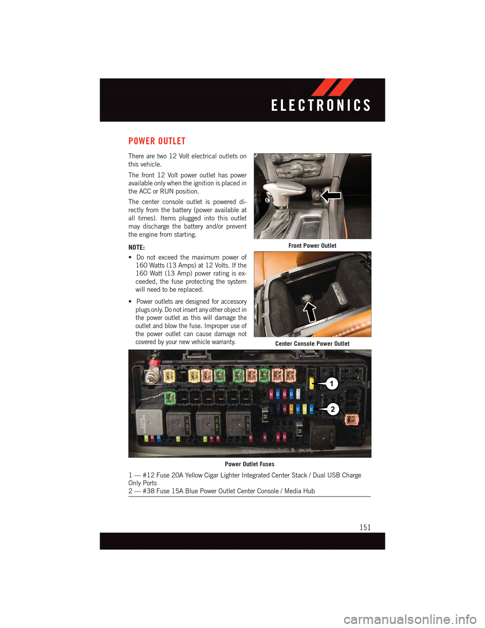
There are two 12 Volt electrical outlets on
this vehicle.
The front 12 Volt power outlet has power
available only when the ignition is placed in
the ACC or RUN position.
The center console outlet is powered di-
rectly from the battery (power available at
all times). Items plugged into this outlet
may discharge the battery and/or prevent
the engine from starting.
NOTE:
•Donotexceedthemaximumpowerof
160 Watts (13 Amps) at 12 Volts. If the
160 Watt (13 Amp) power rating is ex-
ceeded, the fuse protecting the system
will need to be replaced.
•Power outlets are designed for accessory
plugs only. Do not insert any other object in
the power outlet as this will damage the
outlet and blow the fuse. Improper use of
the power outlet can cause damage not
covered by your new vehicle warranty.
Front Power Outlet
Center Console Power Outlet
Power Outlet Fuses
1—#12Fuse20AYellowCigarLighterIntegratedCenterStack/DualUSBChargeOnly Ports2—#38Fuse15ABluePowerOutletCenterConsole/MediaHub
ELECTRONICS
151
Page 154 of 236
TRAILER TOWING WEIGHTS (MAXIMUM TRAILER WEIGHT
RATINGS)
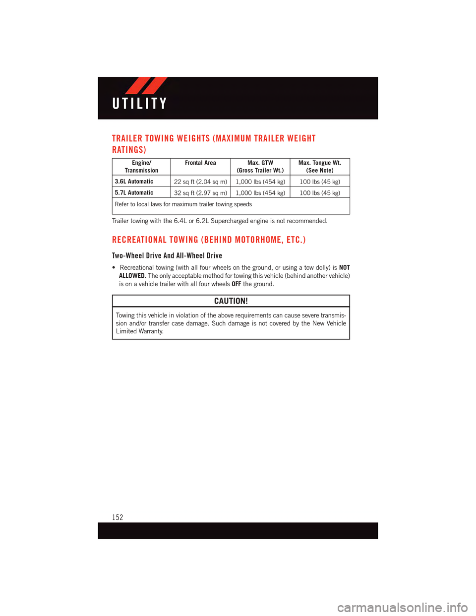
Engine/TransmissionFrontal Area Max. GTW(Gross Trailer Wt.)Max. Tongue Wt.(See Note)
3.6L Automatic22 sq ft (2.04 sq m) 1,000 lbs (454 kg) 100 lbs (45 kg)
5.7L Automatic32 sq ft (2.97 sq m) 1,000 lbs (454 kg) 100 lbs (45 kg)
Refer to local laws for maximum trailer towing speeds
Tr a i l e r t o w i n g w i t h t h e 6 . 4 L o r 6 . 2 L S u p e r c h a r g e d e n g i n e i s n o t r e c o m m e n d e d .
RECREATIONAL TOWING (BEHIND MOTORHOME, ETC.)
Two-Wheel Drive And All-Wheel Drive
•Recreationaltowing(withallfourwheelsontheground,orusingatowdolly)isNOT
ALLOWED.Theonlyacceptablemethodfortowingthisvehicle(behindanothervehicle)
is on a vehicle trailer with all four wheelsOFFthe ground.
CAUTION!
To w i n g t h i s v e h i c l e i n v i o l a t i o n o f t h e a b o v e r e q u i r e m e n t s c a n c a u s e s e v e r e t r a n s m i s -
sion and/or transfer case damage. Such damage is not covered by the New Vehicle
Limited Warranty.
UTILITY
152
Page 155 of 236
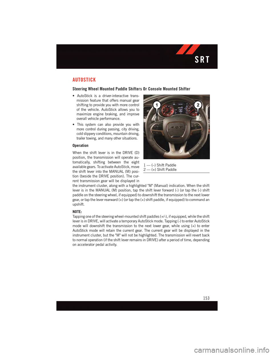
AUTOSTICK
Steering Wheel Mounted Paddle Shifters Or Console Mounted Shifter
•AutoStickisadriver-interactivetrans-
mission feature that offers manual gear
shifting to provide you with more control
of the vehicle. AutoStick allows you to
maximize engine braking, and improve
overall vehicle performance.
•This system can also provide you with
more control during passing, city driving,
cold slippery conditions, mountain driving,
trailer towing, and many other situations.
Operation
When the shift lever is in the DRIVE (D)
position, the transmission will operate au-
tomatically, shifting between the eight
available gears. To activate AutoStick, move
the shift lever into the MANUAL (M) posi-
tion (beside the DRIVE position). The cur-
rent transmission gear will be displayed in
the instrument cluster, along with a highlighted "M" (Manual) indication. When the shift
lever is in the MANUAL (M) position, tap the shift lever forward (-) (or tap the (-) shift
paddle on the steering wheel, if equipped) to downshift the transmission to the next lower
gear, or tap the lever rearward (+) (or tap the (+) shift paddle, if equipped) to command an
upshift.
NOTE:
Ta p p i n g o n e o f t h e s t e e r i n g w h e e l - m o u n t e d s h i f t p a d d l e s ( + / - ) , i f e q u i p p e d , w h i l e t h e s h i f t
lever is in DRIVE, will activate a temporary AutoStick mode. Tapping (-) to enter AutoStick
mode will downshift the transmission to the next lower gear, while using (+) to enter
AutoStick mode will retain the current gear. The current gear will be displayed in the
instrument cluster, but the "M" will not be highlighted. The transmission will revert back
to normal operation (if the shift lever remains in DRIVE) after a period of time, depending
on accelerator pedal activity.
1—(–)ShiftPaddle2—(+)ShiftPaddle
SRT
153
Page 156 of 236
![DODGE CHARGER 2015 7.G User Guide In AutoStick mode, the transmission will shift up or down when (+/-) is manually selected
by the driver (using the shift lever, or the shift paddles [if equipped]), unless an engine
lugging or overspe DODGE CHARGER 2015 7.G User Guide In AutoStick mode, the transmission will shift up or down when (+/-) is manually selected
by the driver (using the shift lever, or the shift paddles [if equipped]), unless an engine
lugging or overspe](/img/12/5581/w960_5581-155.png)
In AutoStick mode, the transmission will shift up or down when (+/-) is manually selected
by the driver (using the shift lever, or the shift paddles [if equipped]), unless an engine
lugging or overspeed condition would result. It will remain in the selected gear until
another upshift or downshift is chosen, except as described below.
•IntemporaryAutoStickmode(shiftleverinDRIVE),thetransmissionwillautomatically
shift up when maximum engine speed is reached. If the accelerator is fully depressed,
the transmission will downshift when possible (based on current vehicle speed and
gear, except 6.4L models). Lack of accelerator pedal activity will cause the transmis-
sion to revert to automatic operation.
•IfnormalAutoStickmodeisengaged(shiftleverinMANUALposition),manualgear
selection will be maintained until the shift lever is returned to DRIVE, or as described
below. The transmission will not upshift automatically at redline in this mode, nor will
downshifts be obtained if the accelerator pedal is pressed to the floor.
•Thetransmissionwillautomaticallydownshiftasthevehicleslows(topreventengine
lugging) and will display the current gear.
•Thetransmissionwillautomaticallydownshifttofirstgearwhencomingtoastop.After
astop,thedrivershouldmanuallyupshift(+)thetransmissionasthevehicleis
accelerated.
•Youcanstartout,fromastop,infirstorsecondgear.Tapping(+)(atastop)willallow
starting in second gear. Starting out in second gear can be helpful in snowy or icy
conditions.
•Ifarequesteddownshiftwouldcausetheenginetoover-speed,thatshiftwillnotoccur.
•Thesystemwillignoreattemptstoupshiftattoolowofavehiclespeed.
•Holdingthe(-)paddledepressed(ifequipped),orholdingtheshiftleverinthe(-)
position, will downshift the transmission to the lowest gear possible at the current
speed.
•TransmissionshiftingwillbemorenoticeablewhenAutoStickisengaged.
•Thesystemmayreverttoautomaticshiftmodeifafaultoroverheatconditionis
detected.
To d i s e n g a g e A u t o S t i c k m o d e , r e t u r n t h e s h i f t l e v e r t o t h e D R I V E p o s i t i o n , o r p r e s s a n d
hold the (+) shift paddle (if equipped, and the shift lever is already in DRIVE) until “D” is
once again indicated in the instrument cluster. You can shift in or out of the AutoStick
mode at any time without taking your foot off the accelerator pedal.
WARNING!
Do not downshift for additional engine braking on a slippery surface. The drive wheels
could lose their grip and the vehicle could skid, causing a collision or personal injury.
SRT
154
Page 157 of 236
DRIVE MODES
Yo u r S RT v e h i c l e i s e q u i p p e d w i t h a S RT D r i v e M o d e f e a t u r e . T h i s f e a t u r e g i v e s t h e d r i v e r
control over the systems in the vehicle which affect its performance, enabling the driver
to tune it for desired driving scenarios.
NOTE:
Refer to the “Drive Mode Supplement” within your Owners Information kit for further
descriptions of these modes.
SRT PERFORMANCE FEATURES
SRT Driver Information Display (DID)
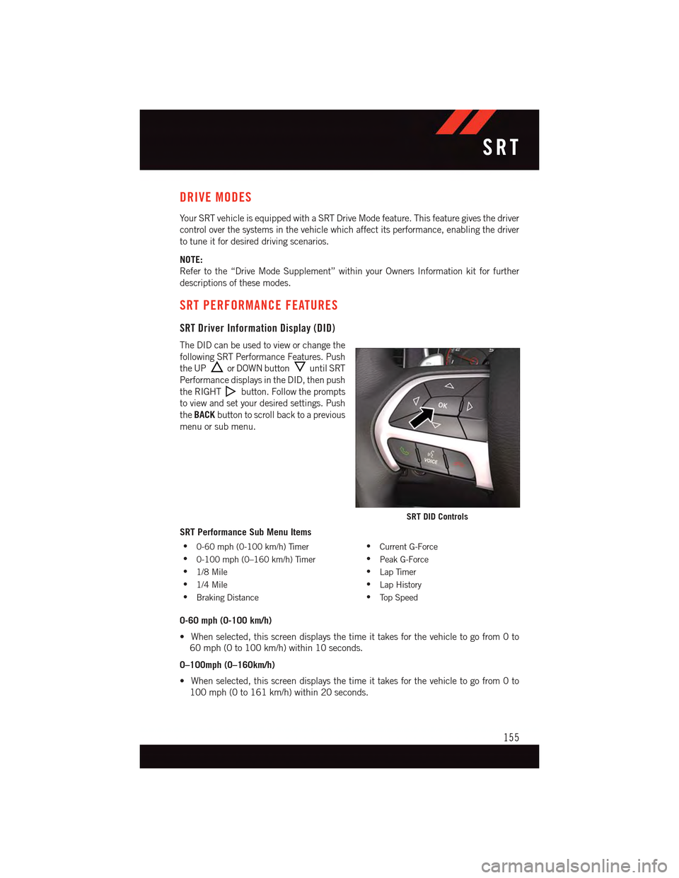
The DID can be used to view or change the
following SRT Performance Features. Push
the UPor DOWN buttonuntil SRT
Performance displays in the DID, then push
the RIGHTbutton. Follow the prompts
to view and set your desired settings. Push
theBACKbutton to scroll back to a previous
menu or sub menu.
SRT Performance Sub Menu Items
•0-60 mph (0-100 km/h) Timer•Current G-Force
•0-100 mph (0–160 km/h) Timer•Peak G-Force
•1/8 Mile•Lap Timer
•1/4 Mile•Lap History
•Braking Distance•To p S p e e d
0-60 mph (0-100 km/h)
•Whenselected,thisscreendisplaysthetimeittakesforthevehicletogofrom0to
60 mph (0 to 100 km/h) within 10 seconds.
0–100mph (0–160km/h)
•Whenselected,thisscreendisplaysthetimeittakesforthevehicletogofrom0to
100 mph (0 to 161 km/h) within 20 seconds.
SRT DID Controls
SRT
155
Page 158 of 236
1/8 Mile, 1/4 Mile
•Whenselected,thisscreendisplaysthetimeittakesthevehicletotravel1/8mile
(1/4 mile) within 30 seconds and the vehicle's speed when it reaches 1/8 mile
(1/4 mile).
Braking Distance
•Whenselected,thisscreendisplaysthevehicle'sbrakingdistanceandthespeedat
which the brake pedal was depressed.
Current G-Force
•Whenselected,thisscreendisplaysthecurrentG-Force(lateralandlongitudinal)along
with a friction circle that displays the directions of the forces.
Peak G-Force
•Whenselected,thisscreendisplaysallfourG-Forcevalues(twolateralandtwo
longitudinal).
Lap Timer
•WhenselectedtheLapTimerpagewillshowthetimeralwaysat0:00.00withthe
previous Best and Last time data (unless the driver has cleared it via hold to Reset)
Lap History
•Whenselected,thisscreendisplaystheLapHistory,andwillcolorhighlightthetime
that is the best time from the Timer Page.
Top Speed
•Whenselected,thisscreendisplaystheTopSpeedsincelastreset.
Uconnect® SRT PERFORMANCE PAGES
To a c c e s s t h e S R T P e r f o r m a n c e P a g e s , p r e s s t h e “ S R T & A p p s ” b u t t o n o n t h e t o u c h -
screen then press the “SRT Performance” button on the touchscreen. Press the feature
button on the touchscreen to select that feature.
The Performance Pages includes the following menus:
•Home•Gauges 2
•Ti m e r s•G–Force
•Gauges 1•Engine
Home
When Home is selected, the following options will be available:
•Aseriesofsiximageswhichcanbeselectedbytheuser.
•Aleftandrightarrowtoallowtheusertoscrollthroughvehicleimages.
•Ashort-cuttotheSRTDriveModesfeature.
SRT
156
Page 159 of 236
Timers
When the Timers Page is selected you will be able to select from following “Tickets”:
Current
•Pressingthe“Current”buttondisplaysa“realtime”summaryofperformancetimers.
Last
•Pressingthe“Last”buttondisplaysthelastrecordedrunofperformancetimers.
Best
•Pressingthe“Best”buttondisplaysthebestrecordedrunofperformancetimers,
except for braking data.
Save
•Pressingthe“Save”buttonwillletyousavethelastrun.Anysavedrunover10,will
overwrite the last saved run for Uconnect®System storage.
Gauges 1
When selected, this screen displays the following values:
•CoolantTemperature
•OilPressure
•OilTemperature
•BatteryVoltage(6.2LOnly)
•TransOilTemp(6.2LOnly)
Gauges 2
When selected, this screen displays the following values for the 6.2L:
•BoostPressure
•AirFuelRatio
•Inter-Cooler(I/C)CoolantTemperature
•IntakeAirTemperature
When selected, this screen displays the following values for the 6.4L:
•BatteryVoltage
•IntakeAirTemperature
•TransmissionTemperature
G-Force
When selected, this screen displays the following values:
•LateralG-ForceLeftandRight
•LongitudinalG-ForceForeandAft
•PeakG-ForcesForeAft,LeftandRight
•VehicleSpeed
•SteeringWheelAngle
SRT
157
Page 160 of 236
Engine
When selected, this screen displays the following values:
•VehicleSpeed
•InstantaneousHorsepower/Kilowatts
•InstantaneousTorque
•OilPressure(6.4LOnly)
•Gear
•BoostPressure(6.2LOnly)
SUMMER/THREE-SEASON TIRES
•Thisvehiclemaybeequippedwithwheelsandtirestoenhancetractioninbothwetand
dry conditions.
•Summertiresarenotintendedtobedriveninsnoworonice.
•Summertireshavesignificantlyreducedgripintemperaturesbelow50°F(10°C)
•Usesummertiresonlyinsetsoffour.
NOTE:
Summer tires will not contain the all season designation or mountain/snowflake symbol on
the sidewall of the tire.
WARNING!
Do not use summer tires in snow/ice conditions. You could lose control, resulting in
severe injury or death. Driving too fast for conditions also creates the possibility of loss
of vehicle control.
SRT
158