DODGE DURANGO 2020 Owners Manual
Manufacturer: DODGE, Model Year: 2020, Model line: DURANGO, Model: DODGE DURANGO 2020Pages: 464, PDF Size: 22.14 MB
Page 281 of 464
IN CASE OF EMERGENCY279
(Continued)
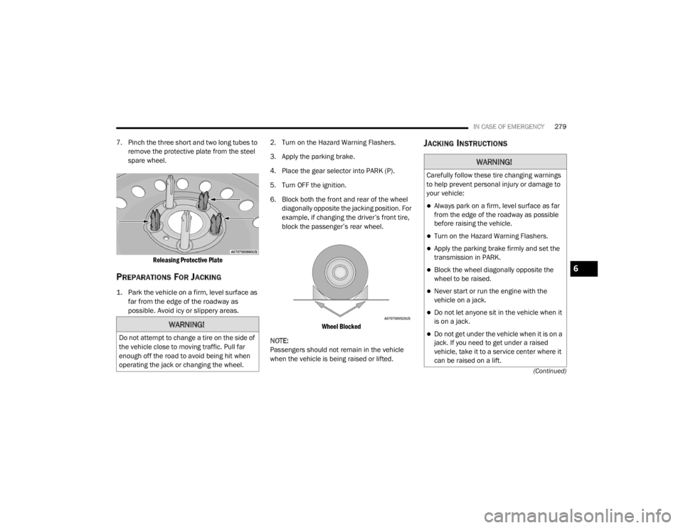
7. Pinch the three short and two long tubes to remove the protective plate from the steel
spare wheel.
Releasing Protective Plate
PREPARATIONS FOR JACKING
1. Park the vehicle on a firm, level surface as far from the edge of the roadway as
possible. Avoid icy or slippery areas.
2. Turn on the Hazard Warning Flashers.
3. Apply the parking brake.
4. Place the gear selector into PARK (P).
5. Turn OFF the ignition.
6. Block both the front and rear of the wheel
diagonally opposite the jacking position. For
example, if changing the driver’s front tire,
block the passenger’s rear wheel.
Wheel Blocked
NOTE:
Passengers should not remain in the vehicle
when the vehicle is being raised or lifted.
JACKING INSTRUCTIONS
WARNING!
Do not attempt to change a tire on the side of
the vehicle close to moving traffic. Pull far
enough off the road to avoid being hit when
operating the jack or changing the wheel.
WARNING!
Carefully follow these tire changing warnings
to help prevent personal injury or damage to
your vehicle:
Always park on a firm, level surface as far
from the edge of the roadway as possible
before raising the vehicle.
Turn on the Hazard Warning Flashers.
Apply the parking brake firmly and set the
transmission in PARK.
Block the wheel diagonally opposite the
wheel to be raised.
Never start or run the engine with the
vehicle on a jack.
Do not let anyone sit in the vehicle when it
is on a jack.
Do not get under the vehicle when it is on a
jack. If you need to get under a raised
vehicle, take it to a service center where it
can be raised on a lift.
6
20_WD_OM_EN_USC_t.book Page 279
Page 282 of 464
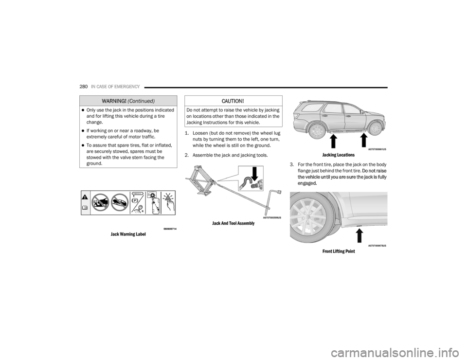
280IN CASE OF EMERGENCY
Jack Warning Label
1. Loosen (but do not remove) the wheel lug
nuts by turning them to the left, one turn,
while the wheel is still on the ground.
2. Assemble the jack and jacking tools.
Jack And Tool Assembly Jacking Locations
3. For the front tire, place the jack on the body flange just behind the front tire. Do not raise
the vehicle until you are sure the jack is fully
engaged.
Front Lifting Point
Only use the jack in the positions indicated
and for lifting this vehicle during a tire
change.
If working on or near a roadway, be
extremely careful of motor traffic.
To assure that spare tires, flat or inflated,
are securely stowed, spares must be
stowed with the valve stem facing the
ground.
WARNING! (Continued)CAUTION!
Do not attempt to raise the vehicle by jacking
on locations other than those indicated in the
Jacking Instructions for this vehicle.
20_WD_OM_EN_USC_t.book Page 280
Page 283 of 464
IN CASE OF EMERGENCY281
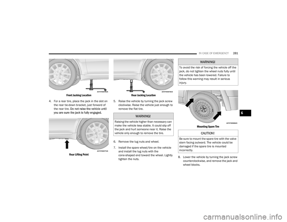
Front Jacking Location
4. For a rear tire, place the jack in the slot on the rear tie-down bracket, just forward of
the rear tire. Do not raise the vehicle until
you are sure the jack is fully engaged.
Rear Lifting Point Rear Jacking Location
5. Raise the vehicle by turning the jack screw clockwise. Raise the vehicle just enough to
remove the flat tire.
6. Remove the lug nuts and wheel.
7. Install the spare wheel/tire on the vehicle and install the lug nuts with the
cone-shaped end toward the wheel. Lightly
tighten the nuts.
Mounting Spare Tire
8. Lower the vehicle by turning the jack screw counterclockwise, and remove the jack and
wheel blocks.
WARNING!
Raising the vehicle higher than necessary can
make the vehicle less stable. It could slip off
the jack and hurt someone near it. Raise the
vehicle only enough to remove the tire.
WARNING!
To avoid the risk of forcing the vehicle off the
jack, do not tighten the wheel nuts fully until
the vehicle has been lowered. Failure to
follow this warning may result in serious
injury.
CAUTION!
Be sure to mount the spare tire with the valve
stem facing outward. The vehicle could be
damaged if the spare tire is mounted
incorrectly.
6
20_WD_OM_EN_USC_t.book Page 281
Page 284 of 464
282IN CASE OF EMERGENCY
9. Finish tightening the lug nuts. Push down on
the wrench while at the end of the handle
for increased leverage. Tighten the lug nuts
in a star pattern until each nut has been
tightened twice. Refer to “Wheel and Tire
Torque Specifications” in “Technical
Specifications” for proper lug nut torque. If
in doubt about the correct tightness, have
them checked with a torque wrench by an
authorized dealer or at a service station.
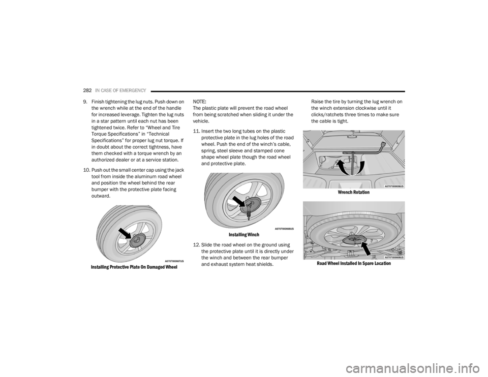
10. Push out the small center cap using the jack tool from inside the aluminum road wheel
and position the wheel behind the rear
bumper with the protective plate facing
outward.
Installing Protective Plate On Damaged Wheel
NOTE:
The plastic plate will prevent the road wheel
from being scratched when sliding it under the
vehicle.
11. Insert the two long tubes on the plastic
protective plate in the lug holes of the road
wheel. Push the end of the winch’s cable,
spring, steel sleeve and stamped cone
shape wheel plate though the road wheel
and protective plate.
Installing Winch
12. Slide the road wheel on the ground using the protective plate until it is directly under
the winch and between the rear bumper
and exhaust system heat shields. Raise the tire by turning the lug wrench on
the winch extension clockwise until it
clicks/ratchets three times to make sure
the cable is tight.
Wrench Rotation
Road Wheel Installed In Spare Location
20_WD_OM_EN_USC_t.book Page 282
Page 285 of 464
IN CASE OF EMERGENCY283
NOTE:
Double check to ensure the tire is snug against
the underbody of the vehicle. Damage to the
winch cable may result if the vehicle is driven
with the tire loose.
13. Lower the jack to the fully closed position.
Return the tools to the proper positions in
the tool bag. Fold the flap on the tool bag
under the tools and roll the tools in the bag
underneath the others. Use the hook and
loop fasteners to secure the tool bag to the
jack with the lug wrench on the forward side
of the jack. Expand the jack on the bracket
by turning the thumb screw clockwise until
it is tight to prevent rattles.
14. Reinstall the plastic plug into the floor of the cargo area. Roll up and store the Jack, Tool
Kit and Tire Changing Instructions. Reinstall
the cover for the jack in the rear storage bin. 15. Have the aluminum road wheel and tire
repaired as soon as possible and properly
secure the spare tire, jack and tool kit.
ROAD TIRE INSTALLATION
1. Mount the road tire on the axle.
2. Install the remaining lug nuts with the cone shaped end of the nut toward the wheel.
Lightly tighten the lug nuts. 3. Lower the vehicle to the ground by turning
the jack handle counterclockwise.
4. Refer to “Wheel and Tire Torque Specifi -
cations” in “Technical Specifications” for
proper lug nut torque.
5. After 25 miles (40 km), check the lug nut torque with a torque wrench to ensure that
all lug nuts are properly seated against the
wheel.
JUMP STARTING
If your vehicle has a discharged battery, it can
be jump started using a set of jumper cables
and a battery in another vehicle, or by using a
portable battery booster pack. Jump starting
can be dangerous if done improperly, so please
follow the procedures in this section carefully.
CAUTION!
The winch mechanism is designed for use
with the jack wrench extension tool only. Use
of air wrench or power tool may damage the
winch.
WARNING!
A loose tire or jack thrown forward in a
collision or hard stop, could endanger the
occupants of the vehicle. Always stow the jack
parts and the spare tire in the places
provided.
WARNING!
To avoid the risk of forcing the vehicle off the
jack, do not tighten the wheel nuts fully until
the vehicle has been lowered. Failure to
follow this warning may result in serious
injury.
WARNING!
Do not attempt jump starting if the battery is
frozen. It could rupture or explode and cause
personal injury.
6
20_WD_OM_EN_USC_t.book Page 283
Page 286 of 464
284IN CASE OF EMERGENCY
(Continued)
NOTE:
When using a portable battery booster pack,
follow the manufacturer's operating instruc-
tions and precautions.
PREPARATIONS FOR JUMP START
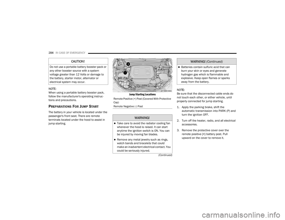
The battery in your vehicle is located under the
passenger's front seat. There are remote
terminals located under the hood to assist in
jump starting.
Jump Starting Locations
NOTE:
Be sure that the disconnected cable ends do
not touch each other, or either vehicle, until
properly connected for jump starting.
1. Apply the parking brake, shift the
automatic transmission into PARK (P) and
turn the ignition OFF.
2. Turn off the heater, radio, and all electrical accessories.
3. Remove the protective cover over the remote positive (+) battery post. Pull
upward on the cover to remove it.
CAUTION!
Do not use a portable battery booster pack or
any other booster source with a system
voltage greater than 12 Volts or damage to
the battery, starter motor, alternator or
electrical system may occur.
Remote Positive (+) Post (Covered With Protective
Cap)
Remote Negative (-) Post
WARNING!
Take care to avoid the radiator cooling fan
whenever the hood is raised. It can start
anytime the ignition switch is ON. You can
be injured by moving fan blades.
Remove any metal jewelry such as rings,
watch bands and bracelets that could
make an inadvertent electrical contact. You
could be seriously injured.
Batteries contain sulfuric acid that can
burn your skin or eyes and generate
hydrogen gas which is flammable and
explosive. Keep open flames or sparks
away from the battery.
WARNING! (Continued)
20_WD_OM_EN_USC_t.book Page 284
Page 287 of 464
IN CASE OF EMERGENCY285
4. If using another vehicle to jump start the
battery, park the vehicle within the jumper
cables reach, apply the parking brake and
make sure the ignition is OFF.
JUMP STARTING PROCEDURE
NOTE:
Make sure at all times that unused ends of
jumper cables are not contacting each other or
either vehicle while making connections.
Connecting The Jumper Cables
1. Connect the positive
(+) end of the jumper
cable to the remote positive (+)
post of the
discharged vehicle.
2. Connect the opposite end of the positive (+)
jumper cable to the positive (+) post of the
booster battery.
3. Connect the negative end (-) of the jumper
cable to the negative (-) post of the booster
battery.
4. Connect the opposite end of the negative (-)
jumper cable to a good engine ground. A
good engine “ground” is an exposed
metallic/unpainted part of the engine,
frame or chassis, such as an accessory
bracket or large bolt. The ground must be
away from the battery and fuel injection
system. 5. Start the engine in the vehicle that has the
booster battery, let the engine idle a few
minutes, and then start the engine in the
vehicle with the discharged battery.
6. Once the engine is started, remove the jumper cables in the reverse sequence.
WARNING!
Do not allow vehicles to touch each other as
this could establish a ground connection and
personal injury could result.
WARNING!
Failure to follow this jump starting procedure
could result in personal injury or property
damage due to battery explosion.
CAUTION!
Failure to follow these procedures could
result in damage to the charging system of
the booster vehicle or the discharged vehicle.
WARNING!
Do not connect the jumper cable to the
negative (-) post of the discharged battery.
The resulting electrical spark could cause the
battery to explode and could result in
personal injury.
CAUTION!
Do not run the booster vehicle engine above
2,000 RPM since it provides no charging
benefit, wastes fuel, and can damage booster
vehicle engine.6
20_WD_OM_EN_USC_t.book Page 285
Page 288 of 464
286IN CASE OF EMERGENCY
Disconnecting The Jumper Cables
1. Disconnect the negative
(-) end of the
jumper cable from the remote negative (-)
post of the discharged vehicle.
2. Disconnect the opposite end of the negative (-) jumper cable from the negative (-) post of
the booster battery.
3. Disconnect the positive (+) end of the
jumper cable from the positive (+) post of
the booster battery.
4. Disconnect the opposite end of the positive (+) jumper cable from the remote positive
(+) post of the discharged vehicle.
5. Reinstall the protective cover over the remote positive (+) post of the discharged
vehicle.
If frequent jump starting is required to start your
vehicle have the battery and charging system
tested at an authorized dealer.
REFUELING IN EMERGENCY – IF EQUIPPED
The fuel filling procedure for in case of an
emergency is described in the “Emergency Gas
Can Refueling” procedure. Refer to “Refueling
The Vehicle” in “Starting And Operating” for
further information.
The vehicle is equipped with a refueling funnel.
If refueling is necessary, while using an
approved gas can, please insert the refueling
funnel into the filler neck opening.
Refueling Funnel
Inserting Funnel
CAUTION!
Accessories plugged into the vehicle power
outlets draw power from the vehicle’s battery,
even when not in use (i.e., cellular devices,
etc.). Eventually, if plugged in long enough
without engine operation, the vehicle’s
battery will discharge sufficiently to degrade
battery life and/or prevent the engine from
starting.
20_WD_OM_EN_USC_t.book Page 286
Page 289 of 464
IN CASE OF EMERGENCY287
IF YOUR ENGINE OVERHEATS
In any of the following situations, you can
reduce the potential for overheating by taking
the appropriate action.
On the highways — slow down.
In city traffic — while stopped, place the trans -
mission in NEUTRAL (N), but do not increase
the engine idle speed while preventing
vehicle motion with the brakes.
NOTE:
There are steps that you can take to slow down
an impending overheat condition:
If your Air Conditioner (A/C) is on, turn it off.
The A/C system adds heat to the engine
cooling system and turning the A/C off can
help remove this heat.
You can also turn the temperature control to
maximum heat, the mode control to floor and
the blower control to high. This allows the
heater core to act as a supplement to the
radiator and aids in removing heat from the
engine cooling system.
MANUAL PARK RELEASE
To move the vehicle in cases where the
transmission will not shift out of PARK (P) (such
as a depleted battery), a Manual Park Release
is available.
WARNING!
You or others can be badly burned by hot
engine coolant (antifreeze) or steam from
your radiator. If you see or hear steam coming
from under the hood, do not open the hood
until the radiator has had time to cool. Never
try to open a cooling system pressure cap
when the radiator or coolant bottle is hot.
CAUTION!
Driving with a hot cooling system could
damage your vehicle. If the temperature
gauge reads HOT (H), pull over and stop the
vehicle. Idle the vehicle with the air
conditioner turned off until the pointer drops
back into the normal range. If the pointer
remains on HOT (H), and you hear continuous
chimes, turn the engine off immediately and
call for service.
WARNING!
Always secure your vehicle by fully applying
the parking brake before activating the
Manual Park Release. In addition, you should
be seated in the driver’s seat with your foot
firmly on the brake pedal when activating the
Manual Park Release. Activating the Manual
Park Release will allow your vehicle to roll
away if it is not secured by the parking brake,
or by proper connection to a tow vehicle.
Activating the Manual Park Release on an
unsecured vehicle could lead to serious injury
or death for those in or around the vehicle.
6
20_WD_OM_EN_USC_t.book Page 287
Page 290 of 464
288IN CASE OF EMERGENCY
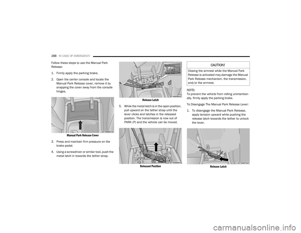
Follow these steps to use the Manual Park
Release:
1. Firmly apply the parking brake.
2. Open the center console and locate the
Manual Park Release cover, remove it by
snapping the cover away from the console
hinges.
Manual Park Release Cover
3. Press and maintain firm pressure on the brake pedal.
4. Using a screwdriver or similar tool, push the metal latch in towards the tether strap.
Release Latch
5. While the metal latch is in the open position, pull upward on the tether strap until the
lever clicks and latches in the released
position. The transmission is now out of
PARK (P) and the vehicle can be moved.
Released Position
NOTE:
To prevent the vehicle from rolling unintention
-
ally, firmly apply the parking brake.
To Disengage The Manual Park Release Lever:
1. To disengage the Manual Park Release, apply tension upward while pushing the
release latch towards the tether to unlock
the lever.
Release Latch
CAUTION!
Closing the armrest while the Manual Park
Release is activated may damage the Manual
Park Release mechanism, the transmission,
and/or the armrest.
20_WD_OM_EN_USC_t.book Page 288