maintenance DODGE NEON 1999 Service Service Manual
[x] Cancel search | Manufacturer: DODGE, Model Year: 1999, Model line: NEON, Model: DODGE NEON 1999Pages: 1200, PDF Size: 35.29 MB
Page 726 of 1200
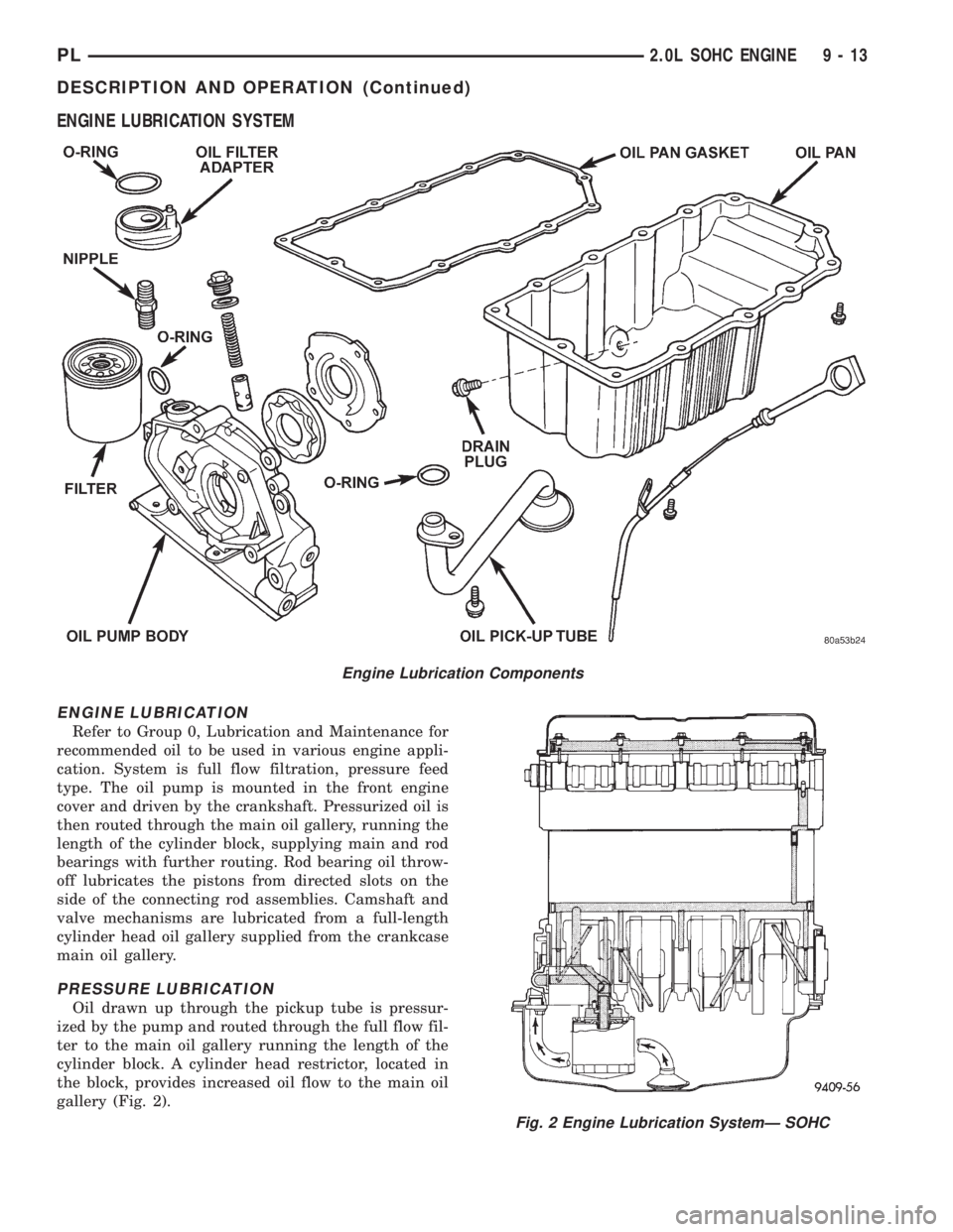
ENGINE LUBRICATION SYSTEM
ENGINE LUBRICATION
Refer to Group 0, Lubrication and Maintenance for
recommended oil to be used in various engine appli-
cation. System is full flow filtration, pressure feed
type. The oil pump is mounted in the front engine
cover and driven by the crankshaft. Pressurized oil is
then routed through the main oil gallery, running the
length of the cylinder block, supplying main and rod
bearings with further routing. Rod bearing oil throw-
off lubricates the pistons from directed slots on the
side of the connecting rod assemblies. Camshaft and
valve mechanisms are lubricated from a full-length
cylinder head oil gallery supplied from the crankcase
main oil gallery.
PRESSURE LUBRICATION
Oil drawn up through the pickup tube is pressur-
ized by the pump and routed through the full flow fil-
ter to the main oil gallery running the length of the
cylinder block. A cylinder head restrictor, located in
the block, provides increased oil flow to the main oil
gallery (Fig. 2).
Engine Lubrication Components
Fig. 2 Engine Lubrication SystemÐ SOHC
PL2.0L SOHC ENGINE 9 - 13
DESCRIPTION AND OPERATION (Continued)
Page 771 of 1200
2.0L DOHC ENGINE
INDEX
page page
DESCRIPTION AND OPERATION
ENGINE COMPONENTS.................. 59
ENGINE IDENTIFICATION NUMBER......... 58
ENGINE LUBRICATION SYSTEM............ 58
GENERAL SPECIFICATION................ 58
DIAGNOSIS AND TESTING
CHECKING ENGINE OIL PRESSURE......... 60
SERVICE PROCEDURES
CRANKSHAFT END PLAY................. 63
CYLINDER BORE AND PISTON SIZING....... 60
FITTING CONNECTING RODS.............. 62
FITTING CRANKSHAFT BEARINGS.......... 62
FITTING PISTON RINGS.................. 61
REMOVAL AND INSTALLATION
CAMSHAFT OIL SEALS................... 81
CAM FOLLOWER AND HYDRAULIC LASH
ADJUSTER ASSEMBLY.................. 69
CAMSHAFT............................ 67
CRANKSHAFT DAMPER.................. 73
CRANKSHAFT OIL SEALÐFRONT........... 82
CRANKSHAFT OIL SEALÐREAR............ 83
CRANKSHAFT.......................... 85
CYLINDER HEAD COVER................. 67
CYLINDER HEAD........................ 71
ENGINE ASSEMBLY...................... 65
ENGINE MOUNTÐFRONT................. 63
ENGINE MOUNTÐLEFT................... 63
ENGINE MOUNTÐRIGHT................. 64OIL FILTER ADAPTER.................... 87
OILFILTER ............................ 87
OILPAN ............................... 81
OIL PUMP............................. 88
PISTON AND CONNECTING ROD........... 89
POWER HOP DAMPER................... 64
STRUCTURAL COLLARÐ2.0L.............. 64
TIMING BELT COVER.................... 74
TIMING BELT TENSIONERÐMECHANICAL.... 80
TIMING BELTÐWITH HYDRAULIC TENSIONER . 75
TIMING BELTÐWITH MECHANICAL
TENSIONER.......................... 78
VALVE SPRING AND SEALSÐ
CYLINDER HEAD NOT REMOVED......... 69
DISASSEMBLY AND ASSEMBLY
OIL PUMP............................. 91
VALVE SERVICE WITH CYLINDER HEAD
REMOVED........................... 91
CLEANING AND INSPECTION
CYLINDER BLOCK AND BORE............. 96
CYLINDER HEAD AND CAMSHAFT JOURNALS . 94
OIL PUMP............................. 94
SPECIFICATIONS
2.0L DOHC............................. 96
TORQUE CHART 2.0L DOHC............... 98
SPECIAL TOOLS
2.0L DOHC............................. 98
DESCRIPTION AND OPERATION
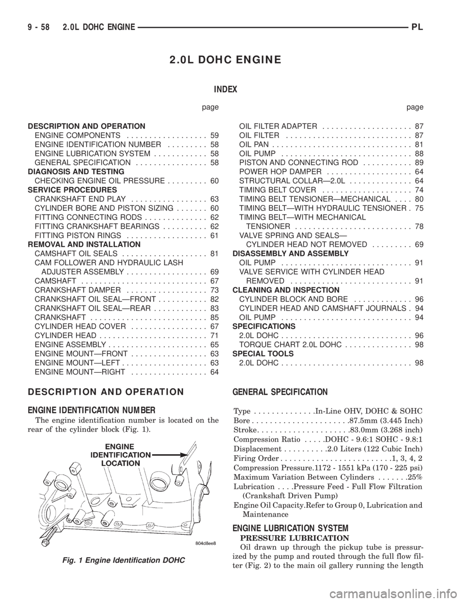
ENGINE IDENTIFICATION NUMBER
The engine identification number is located on the
rear of the cylinder block (Fig. 1).
GENERAL SPECIFICATION
Type ..............In-Line OHV, DOHC & SOHC
Bore......................87.5mm (3.445 Inch)
Stroke.....................83.0mm (3.268 inch)
Compression Ratio.....DOHC - 9.6:1 SOHC - 9.8:1
Displacement..........2.0 Liters (122 Cubic Inch)
Firing Order.........................1,3,4,2
Compression Pressure.1172 - 1551 kPa (170 - 225 psi)
Maximum Variation Between Cylinders.......25%
Lubrication. . . .Pressure Feed - Full Flow Filtration
(Crankshaft Driven Pump)
Engine Oil Capacity.Refer to Group 0, Lubrication and
Maintenance
ENGINE LUBRICATION SYSTEM
PRESSURE LUBRICATION
Oil drawn up through the pickup tube is pressur-
ized by the pump and routed through the full flow fil-
ter (Fig. 2) to the main oil gallery running the length
Fig. 1 Engine Identification DOHC
9 - 58 2.0L DOHC ENGINEPL
Page 817 of 1200
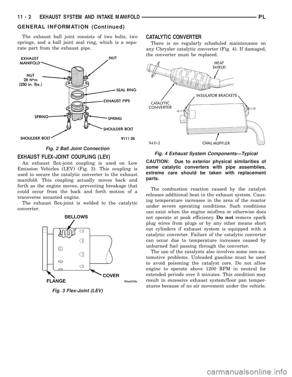
The exhaust ball joint consists of two bolts, two
springs, and a ball joint seal ring, which is a sepa-
rate part from the exhaust pipe.
EXHAUST FLEX-JOINT COUPLING (LEV)
An exhaust flex-joint coupling is used on Low
Emission Vehicles (LEV) (Fig. 3). This coupling is
used to secure the catalytic converter to the exhaust
manifold. This coupling actually moves back and
forth as the engine moves, preventing breakage that
could occur from the back and forth motion of a
transverse mounted engine.
The exhaust flex-joint is welded to the catalytic
converter.
CATALYTIC CONVERTER
There is no regularly scheduled maintenance on
any Chrysler catalytic converter (Fig. 4). If damaged,
the converter must be replaced.
CAUTION: Due to exterior physical similarities of
some catalytic converters with pipe assemblies,
extreme care should be taken with replacement
parts.
The combustion reaction caused by the catalyst
releases additional heat in the exhaust system. Caus-
ing temperature increases in the area of the reactor
under severe operating conditions. Such conditions
can exist when the engine misfires or otherwise does
not operate at peak efficiency.Do notremove spark
plug wires from plugs or by any other means short
out cylinders if exhaust system is equipped with a
catalytic converter. Failure of the catalytic converter
can occur due to temperature increases caused by
unburned fuel passing through the converter.
The use of the catalysts also involves some non-au-
tomotive problems. Unleaded gasoline must be used
to avoid poisoning the catalyst core. Do not allow
engine to operate above 1200 RPM in neutral for
extended periods over 5 minutes. This condition may
result in excessive exhaust system/floor pan temper-
atures because of no air movement under the vehicle.
Fig. 2 Ball Joint Connection
Fig. 3 Flex-Joint (LEV)
Fig. 4 Exhaust System ComponentsÐTypical
11 - 2 EXHAUST SYSTEM AND INTAKE MANIFOLDPL
GENERAL INFORMATION (Continued)
Page 840 of 1200

FRAME AND BUMPERS
CONTENTS
page
FRAME................................ 1
FRAME
INDEX
page page
REMOVAL AND INSTALLATION
FRONT TOW HOOK BRACKET............. 1REAR TOW HOOK BRACKET.............. 1
REMOVAL AND INSTALLATION
FRONT TOW HOOK BRACKET
REMOVAL
(1) Hoist and support vehicle. Refer to Group 0,
Lubrication and Maintenance, for proper lifting pro-
cedures.
(2) Remove bolts holding front tow hook bracket to
lower radiator crossmember.
(3) Separate front tow hook bracket from vehicle.
INSTALLATION
(1) Position front tow hook bracket to vehicle.
(2) Install bolts to hold front tow hook bracket to
lower radiator crossmember.(3) Lower vehicle.
REAR TOW HOOK BRACKET
REMOVAL
(1) Hoist and support vehicle. Refer to Group 0,
Lubrication and Maintenance, for proper lifting pro-
cedure.
(2) Remove bolts holding rear tow hook bracket to
rear frame rail (Fig. 2).
(3) Separate rear tow hook bracket from vehicle.
INSTALLATION
(1) Position rear tow hook bracket on vehicle.
(2) Install bolts to hold rear tow hook bracket to
rear frame rail.
(3) Lower vehicle.
Fig. 1 Front Tow Hook BracketFig. 2 Rear Tow Hook Bracket
PLFRAME AND BUMPERS 13 - 1
Page 919 of 1200
(2) Install power steering fluid supply hose on
power steering fluid reservoir fitting. Install hose
clamp on power steering fluid supply hose at power
steering fluid reservoir (Fig. 19).Be sure hose
clamp is installed on return hose past upset
bead on power steering fluid reservoir.
(3) Install power steering fluid supply hose on
power steering pump fitting. Install hose clamp on
power steering fluid supply hose at power steering
pump fitting (Fig. 20).Be sure hose clamp is
installed on power steering fluid supply hose
past upset bead on power steering pump fit-
ting.
(4) Start the engine and let run for a few seconds.
Then turn the engine off.
(5) Add fluid if necessary. Repeat the above proce-
dure until the fluid level remains constant after run-
ning the engine.
(6) Raise front wheels of vehicle off the ground.
(7) Start the engine. Slowly turn the steering
wheel right and left, lightly contacting the wheel
stops. Then turn the engine off.
(8) Add power steering fluid if necessary.
(9) Lower the vehicle and turn the steering wheel
slowly from lock to lock.
(10) Stop the engine. Check the fluid level and
refill as required.
(11) If the fluid is extremely foamy, allow the vehi-
cle to stand a few minutes and repeat the above pro-
cedure.
(12) After hose is installed, check for leaks at all
hose connections.
POWER STEERING PUMP (ALL ENGINES)
WARNING: POWER STEERING OIL, ENGINE COM-
PONENTS AND EXHAUST SYSTEM MAY BE
EXTREMELY HOT IF ENGINE HAS BEEN RUNNING.
DO NOT START ENGINE WITH ANY LOOSE OR DIS-
CONNECTED HOSES, OR ALLOW HOSES TO
TOUCH HOT EXHAUST MANIFOLD OR CATALYST.
The power steering pump removal procedure and
pump and bracket fastener locations are the same for
both engine applications used for this vehicle. The
front power steering pump bracket must be removed
as an assembly with the power steering pump and
removed from the pump after removing the pulley
from the power steering pump.
REMOVE
(1) Remove battery cable from (-) negative post on
battery.
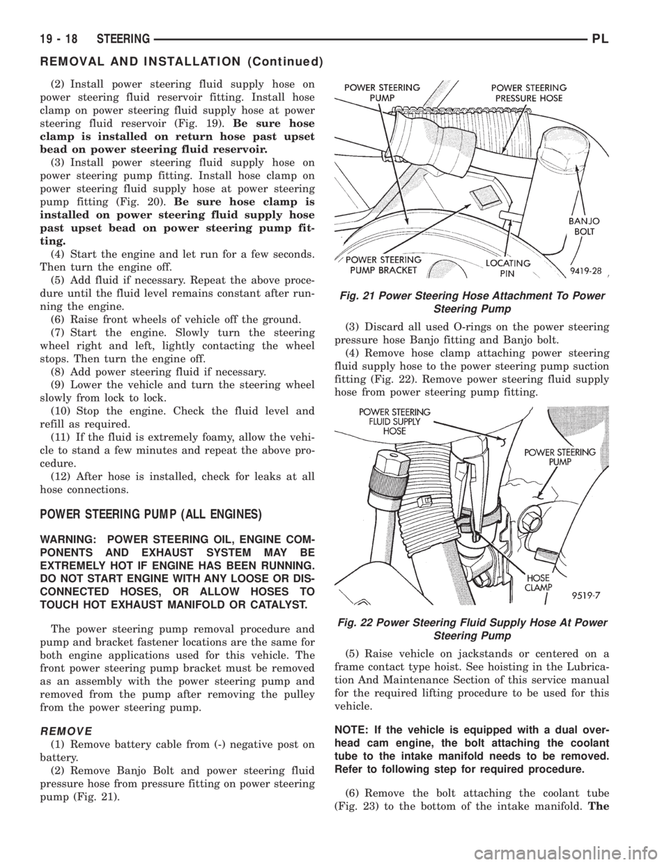
(2) Remove Banjo Bolt and power steering fluid
pressure hose from pressure fitting on power steering
pump (Fig. 21).(3) Discard all used O-rings on the power steering
pressure hose Banjo fitting and Banjo bolt.
(4) Remove hose clamp attaching power steering
fluid supply hose to the power steering pump suction
fitting (Fig. 22). Remove power steering fluid supply
hose from power steering pump fitting.
(5) Raise vehicle on jackstands or centered on a
frame contact type hoist. See hoisting in the Lubrica-
tion And Maintenance Section of this service manual
for the required lifting procedure to be used for this
vehicle.
NOTE: If the vehicle is equipped with a dual over-
head cam engine, the bolt attaching the coolant
tube to the intake manifold needs to be removed.
Refer to following step for required procedure.
(6) Remove the bolt attaching the coolant tube
(Fig. 23) to the bottom of the intake manifold.The
Fig. 21 Power Steering Hose Attachment To Power
Steering Pump
Fig. 22 Power Steering Fluid Supply Hose At Power
Steering Pump
19 - 18 STEERINGPL
REMOVAL AND INSTALLATION (Continued)
Page 922 of 1200
(23) If the fluid is extremely foamy, allow the vehi-
cle to stand a few minutes and repeat the above pro-
cedure.
(24) After power steering pump is installed, check
for leaks at all hose connections and power steering
pump fittings.
POWER STEERING FLUID RESERVOIR
REMOVE
(1) Raise vehicle on jack stands or on a frame con-
tact type hoist. See Hoisting in the Lubrication And
Maintenance Section of this service manual for the
required lifting procedure to be used for this vehicle.
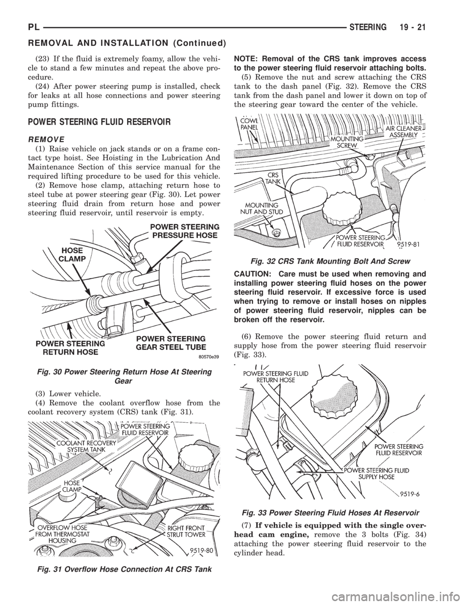
(2) Remove hose clamp, attaching return hose to
steel tube at power steering gear (Fig. 30). Let power
steering fluid drain from return hose and power
steering fluid reservoir, until reservoir is empty.
(3) Lower vehicle.
(4) Remove the coolant overflow hose from the
coolant recovery system (CRS) tank (Fig. 31).NOTE: Removal of the CRS tank improves access
to the power steering fluid reservoir attaching bolts.
(5) Remove the nut and screw attaching the CRS
tank to the dash panel (Fig. 32). Remove the CRS
tank from the dash panel and lower it down on top of
the steering gear toward the center of the vehicle.
CAUTION: Care must be used when removing and
installing power steering fluid hoses on the power
steering fluid reservoir. If excessive force is used
when trying to remove or install hoses on nipples
of power steering fluid reservoir, nipples can be
broken off the reservoir.
(6) Remove the power steering fluid return and
supply hose from the power steering fluid reservoir
(Fig. 33).
(7)If vehicle is equipped with the single over-
head cam engine,remove the 3 bolts (Fig. 34)
attaching the power steering fluid reservoir to the
cylinder head.
Fig. 30 Power Steering Return Hose At Steering
Gear
Fig. 31 Overflow Hose Connection At CRS Tank
Fig. 32 CRS Tank Mounting Bolt And Screw
Fig. 33 Power Steering Fluid Hoses At Reservoir
PLSTEERING 19 - 21
REMOVAL AND INSTALLATION (Continued)
Page 929 of 1200
pressures are not the same against either stop, the
steering gear is leaking internally and must be
replaced.
REMOVAL AND INSTALLATION
MANUAL AND POWER STEERING GEAR
The removal and replacement procedure for both
the manual and power steering gears is the same.
The only additional steps of the procedure for the
power steering gear, is the removal and replacement
of the power steering fluid lines at the steering gear.
REMOVE
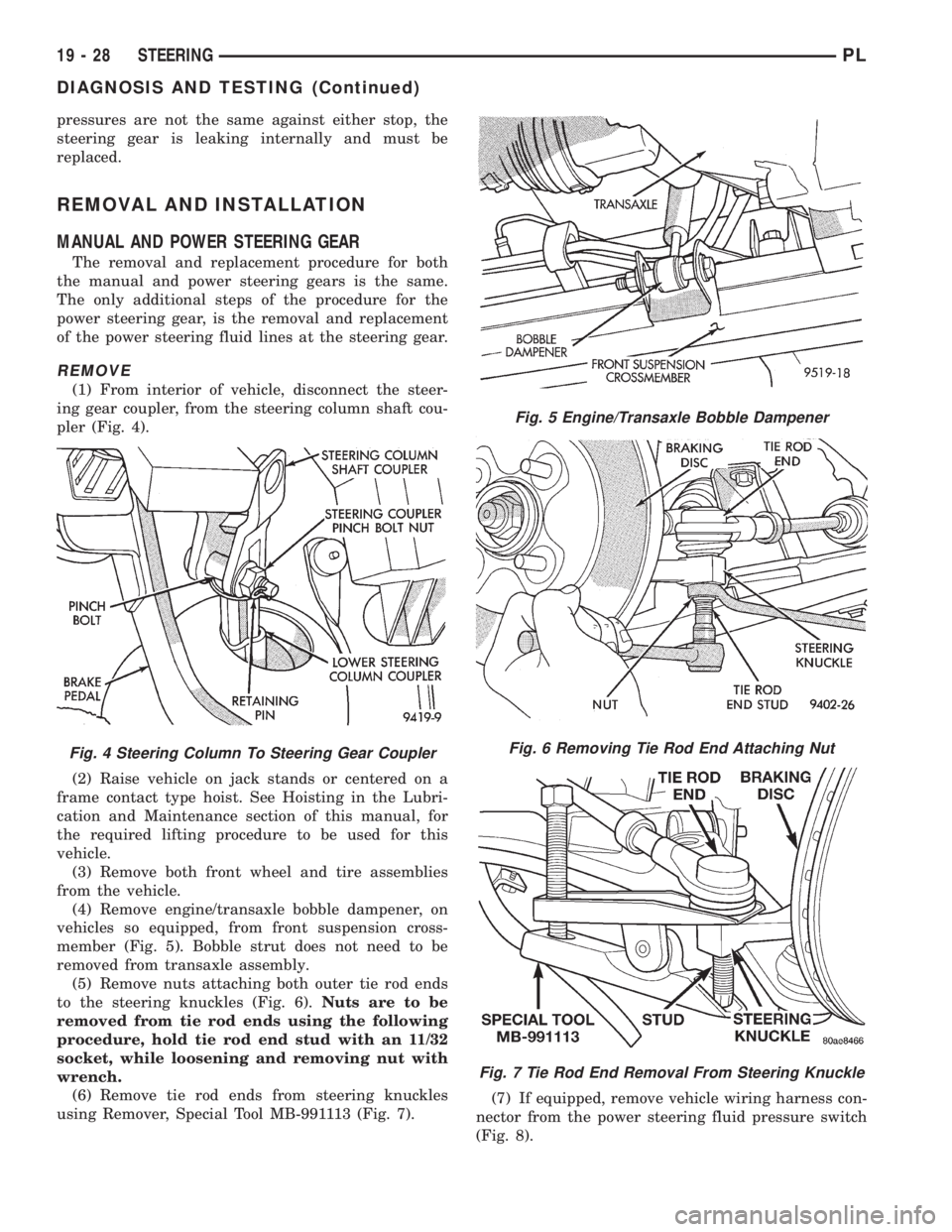
(1) From interior of vehicle, disconnect the steer-
ing gear coupler, from the steering column shaft cou-
pler (Fig. 4).
(2) Raise vehicle on jack stands or centered on a
frame contact type hoist. See Hoisting in the Lubri-
cation and Maintenance section of this manual, for
the required lifting procedure to be used for this
vehicle.
(3) Remove both front wheel and tire assemblies
from the vehicle.
(4) Remove engine/transaxle bobble dampener, on
vehicles so equipped, from front suspension cross-
member (Fig. 5). Bobble strut does not need to be
removed from transaxle assembly.
(5) Remove nuts attaching both outer tie rod ends
to the steering knuckles (Fig. 6).Nuts are to be
removed from tie rod ends using the following
procedure, hold tie rod end stud with an 11/32
socket, while loosening and removing nut with
wrench.
(6) Remove tie rod ends from steering knuckles
using Remover, Special Tool MB-991113 (Fig. 7).(7) If equipped, remove vehicle wiring harness con-
nector from the power steering fluid pressure switch
(Fig. 8).
Fig. 4 Steering Column To Steering Gear Coupler
Fig. 5 Engine/Transaxle Bobble Dampener
Fig. 6 Removing Tie Rod End Attaching Nut
Fig. 7 Tie Rod End Removal From Steering Knuckle
19 - 28 STEERINGPL
DIAGNOSIS AND TESTING (Continued)
Page 1002 of 1200
(6) If fluid flow is still found to be inadequate,
check the line pressure using the Transaxle Hydrau-
lic Pressure Test procedure.
REMOVAL AND INSTALLATION
GEARSHIFT CABLE
REMOVAL
(1) Disconnect both battery cables.
(2) Pull up and remove the power distribution cen-
ter.
(3) Remove the battery thermoguard.
(4) Remove the battery and battery holddown from
the battery tray.
(5) Remove the battery tray and cruise control
servo (if equipped).
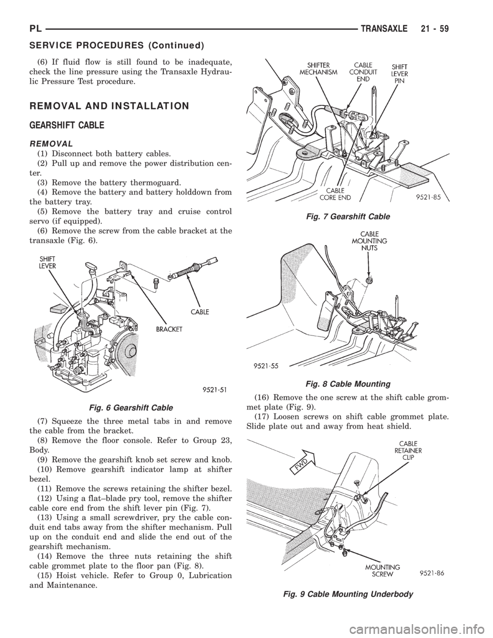
(6) Remove the screw from the cable bracket at the
transaxle (Fig. 6).
(7) Squeeze the three metal tabs in and remove
the cable from the bracket.
(8) Remove the floor console. Refer to Group 23,
Body.
(9) Remove the gearshift knob set screw and knob.
(10) Remove gearshift indicator lamp at shifter
bezel.
(11) Remove the screws retaining the shifter bezel.
(12) Using a flat±blade pry tool, remove the shifter
cable core end from the shift lever pin (Fig. 7).
(13) Using a small screwdriver, pry the cable con-
duit end tabs away from the shifter mechanism. Pull
up on the conduit end and slide the end out of the
gearshift mechanism.
(14) Remove the three nuts retaining the shift
cable grommet plate to the floor pan (Fig. 8).
(15) Hoist vehicle. Refer to Group 0, Lubrication
and Maintenance.(16) Remove the one screw at the shift cable grom-
met plate (Fig. 9).
(17) Loosen screws on shift cable grommet plate.
Slide plate out and away from heat shield.
Fig. 6 Gearshift Cable
Fig. 7 Gearshift Cable
Fig. 8 Cable Mounting
Fig. 9 Cable Mounting Underbody
PLTRANSAXLE 21 - 59
SERVICE PROCEDURES (Continued)
Page 1084 of 1200
DIAGNOSIS AND TESTING
WATER LEAKS
Water leaks can be caused by poor sealing,
improper body component alignment, body seam
porosity, missing plugs, or blocked drain holes. Cen-
trifugal and gravitational force can cause water to
drip from a location away from the actual leak point,
making leak detection difficult. All body sealing
points should be water tight in normal wet-driving
conditions. Water flowing downward from the front of
the vehicle should not enter the passenger or luggage
compartment. Moving sealing surfaces will not
always seal water tight under all conditions. At
times, side glass or door seals will allow water to
enter the passenger compartment during high pres-
sure washing or hard driving rain (severe) condi-
tions. Overcompensating on door or glass
adjustments to stop a water leak that occurs under
severe conditions can cause premature seal wear and
excessive closing or latching effort. After completing
a repair, water-test vehicle to verify leak has stopped
before returning vehicle to use.
VISUAL INSPECTION BEFORE WATER LEAK
TESTS
Verify that floor and body plugs are in place, body
drains are clear, and body components are properly
aligned and sealed. If component alignment or seal-
ing is necessary, refer to the appropriate section of
this group for proper procedures.
WATER LEAK TESTS
WARNING: DO NOT USE ELECTRIC SHOP LIGHTS
OR TOOLS IN WATER TEST AREA. PERSONAL
INJURY CAN RESULT.
When the conditions causing a water leak have
been determined, simulate the conditions as closely
as possible.
²If a leak occurs with the vehicle parked in a
steady light rain, flood the leak area with an open-
ended garden hose.
²If a leak occurs while driving at highway speeds
in a steady rain, test the leak area with a reasonable
velocity stream or fan spray of water. Direct the
spray in a direction comparable to actual conditions.
²If a leak occurs when the vehicle is parked on an
incline, hoist the end or side of the vehicle to simu-
late this condition. This method can be used when
the leak occurs when the vehicle accelerates, stops or
turns. If the leak occurs on acceleration, hoist the
front of the vehicle. If the leak occurs when braking,
hoist the back of the vehicle. If the leak occurs on left
turns, hoist the left side of the vehicle. If the leak
occurs on right turns, hoist the right side of the vehi-cle. For hoisting recommendations refer to Group 0,
Lubrication and Maintenance, General Information
section.
WATER LEAK DETECTION
To detect a water leak point-of-entry, do a water
test and watch for water tracks or droplets forming
on the inside of the vehicle. If necessary, remove inte-
rior trim covers or panels to gain visual access to the
leak area. If the hose cannot be positioned without
being held, have someone help do the water test.
Some water leaks must be tested for a considerable
length of time to become apparent. When a leak
appears, find the highest point of the water track or
drop. The highest point usually will show the point of
entry. After leak point has been found, repair the
leak and water test to verify that the leak has
stopped.
Locating the entry point of water that is leaking
into a cavity between panels can be difficult. The
trapped water may splash or run from the cavity,
often at a distance from the entry point. Most water
leaks of this type become apparent after accelerating,
stopping, turning, or when on an incline.
MIRROR INSPECTION METHOD
When a leak point area is visually obstructed, use
a suitable mirror to gain visual access. A mirror can
also be used to deflect light to a limited-access area
to assist in locating a leak point.
BRIGHT LIGHT LEAK TEST METHOD
Some water leaks in the luggage compartment can
be detected without water testing. Position the vehi-
cle in a brightly lit area. From inside the darkened
luggage compartment inspect around seals and body
seams. If necessary, have a helper direct a drop light
over the suspected leak areas around the luggage
compartment. If light is visible through a normally
sealed location, water could enter through the open-
ing.
PRESSURIZED LEAK TEST METHOD
When a water leak into the passenger compart-
ment cannot be detected by water testing, pressurize
the passenger compartment and soap test exterior of
the vehicle. To pressurize the passenger compart-
ment, close all doors and windows, start engine, and
set heater control to high blower in HEAT position. If
engine can not be started, connect a charger to the
battery to ensure adequate voltage to the blower.
With interior pressurized, apply dish detergent solu-
tion to suspected leak area on the exterior of the
vehicle. Apply detergent solution with spray device or
soft bristle brush. If soap bubbles occur at a body
seam, joint, seal or gasket, the leak entry point could
be at that location.
PLBODY 23 - 3
Page 1137 of 1200
COMPRESSOR
The compressor used on this vehicle is a Nippon-
denso 10PA17 R-134a. This compressor uses an alu-
minum swash plate, teflon coated pistons and
aluminum sleeved cylinder walls.
CAUTION: A 10PA17 R-12 compressor looks identi-
cal to a 10PA17 R-134a and will bolt up to the vehi-
cle. The 10PA17 R-12 compressor must not be used
on this system. It is extremely important that a
10PA17 R-134a compressor is identified prior to
using compressor in question. Check tag located
on compressor for model number.
NOISE
Excessive noise that occurs when the air condition-
ing is being used may be caused by:
²Loose bolts
²Mounting brackets
²Loose compressor clutch
²Excessive high refrigerant operating pressure
Verify the following before compressor repair is
performed:
(1) Compressor drive belt condition
(2) Proper refrigerant charge
(3) Thermal expansion valve (TXV) operating cor-
rectly
(4) Head pressure is normal
COMPRESSOR FRONT SHAFT SEAL
The compressor front shaft seal is not serviceable.
If a leak is detected at the shaft seal, the compressor
must be replaced as a unit.
CONDENSATION DRAIN TUBE
Condensation that accumulates in the evaporator
housing is drained from a tube through the dash and
on to the ground. This tube must be kept open to
prevent condensate water from collecting in the bot-
tom of the housing.
The tapered end of the drain tube is designed to
keep contaminants from entering the heater A/C unit
housing. If the tube is pinched or blocked, condensate
cannot drain, causing water to back up and spill into
the passenger compartment. It is normal to see con-
densate drainage below the vehicle. If the tube is
damaged, it should be replaced.
ENGINE COOLING SYSTEM REQUIREMENTS
To maintain ample temperature levels from the
heating-A/C system, the cooling system must be in
proper working order. Refer to Group 0, Lubrication
and Maintenance or Group 7, Cooling System of this
manual.
The use of a bug screen is not recommended. Any
obstructions forward of the condenser can reduce the
effectiveness of the air conditioning system.
EVAPORATOR PROBE
The evaporator probe can be replaced without hav-
ing to remove the unit housing from the vehicle.
The evaporator probe is located in the unit housing
and placed in the evaporator fins. The probe prevents
evaporator freeze-up. This is done by cycling the com-
pressor clutch OFF when evaporator temperature
drops below freeze point. It cycles ON when the
evaporator temperature rises above freeze point. The
evaporator probe uses a thermistor probe in a capil-
lary tube. The tube is inserted between the evapora-
tor fins in the heater-A/C unit housing.
HANDLING TUBING AND FITTINGS
Kinks in the refrigerant tubing or sharp bends in
the refrigerant hose lines will greatly reduce the
capacity of the entire system. High pressures are pro-
duced in the system when it is operating. Extreme
care must be exercised to make sure that all connec-
tions are pressure tight. Dirt and moisture can enter
the system when it is opened for repair or replace-
ment of lines or components. The refrigerant oil will
absorb moisture readily out of the air. This moisture
will convert into acids within a closed system.
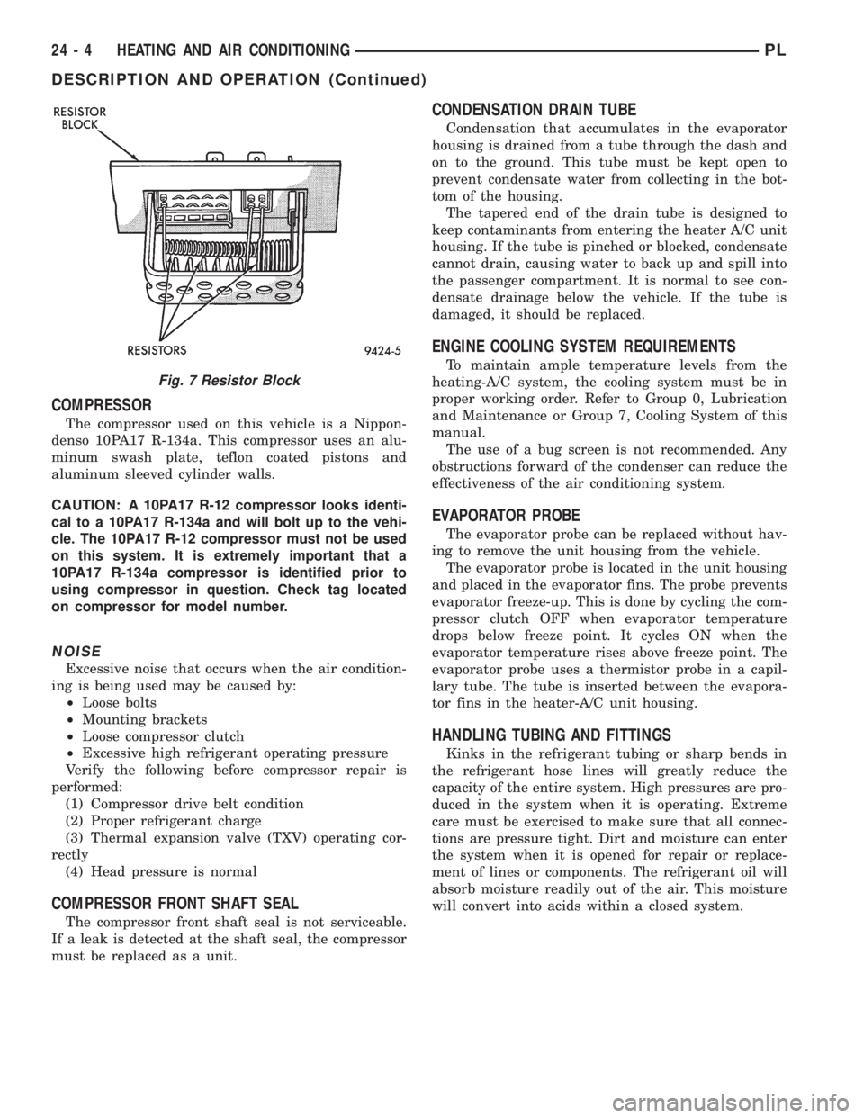
Fig. 7 Resistor Block
24 - 4 HEATING AND AIR CONDITIONINGPL
DESCRIPTION AND OPERATION (Continued)