Timing DODGE NEON 1999 Service Repair Manual
[x] Cancel search | Manufacturer: DODGE, Model Year: 1999, Model line: NEON, Model: DODGE NEON 1999Pages: 1200, PDF Size: 35.29 MB
Page 5 of 1200
²Replace air cleaner element.
²Replace spark plugs.
²Change automatic transmission fluid.
37,500 Miles (60 000 km) or at 30 months
²Change engine oil.
45,000 Miles (72 000 km) or at 36 months
²Change engine oil.
²Replace engine oil filter.
²Inspect front brake pads and rear brake linings.
²Adjust drive belt tension.
²Flush and replace engine coolant at 36 months,
regardless of mileage.
52,500 Miles (84 000 km) or at 42 months
²Change engine oil.
²Flush and replace engine coolant if not done at
36 months.
60,000 Miles (96 000 km) or at 48 months
²Change engine oil.
²Replace engine oil filter.
²Check and replace, if necessary***, the PCV
valve.**
²Lubricate front suspension upper ball joints.
²Replace drive belts.
²Replace air cleaner element.
²Replace ignition cables.
²Replace spark plugs.
²Change automatic transmission fluid.
67,500 Miles (108 000 km) or at 54 months
²Change engine oil.
²Inspect front brake pads and rear brake linings.
75,000 Miles (120 000 km) or at 60 months
²Change engine oil.
²Replace engine oil filter.
²Adjust drive belt tension.
²Flush and replace engine coolant if it has been
30,000 miles (48 000 km) or 24 months since last
change.
82,500 Miles (132 000 km) or at 66 months
²Change engine oil.
²Flush and replace engine coolant if it has been
30,000 miles (48 000 km) or 24 months since last
change.
90,000 Miles (144 000 km) or at 72 months
²Change engine oil.
²Replace engine oil filter.
²Check and replace, if necessary***, the PCV
valve.**
²Lubricate front suspension upper ball joints.
²Inspect front brake pads and rear brake linings.²Adjust drive belt tension.
²Replace air cleaner air cleaner element.
²Replace spark plugs.
²Change automatic transmission fluid.
97,500 Miles (156 000 km) or at 78 months
²Change engine oil.
105,000 Miles (168 000 km)
²Change engine oil.
²Replace engine oil filter.
²Replace engine timing belt
²Adjust drive belt tension.
SCHEDULE ± B
NOTE: * Follow this schedule if you usually operate
your vehicle under one or more of the following
conditions. Change the automatic transmission
fluid and filter every 15,000 miles (24 000 km) if you
usually operate your vehicle under one of the con-
ditions marked with an *.
3,000 Miles (5 000 km)
²Change engine oil
6,000 Miles (10 000 km)
²Change engine oil
²Replace engine oil filter.
9,000 Miles (14 000 km)
²Change engine oil
²Inspect front brake pads and rear brake lining.
12,000 Miles (19 000 km)
²Change engine oil
²Replace engine oil filter.
15,000 Miles (24 000 km)
²Change engine oil
²Adjust drive belt tension.
²Inspect and replace, if required, the air
cleaner element.
²Change automatic transaxle fluid and filter.
Adjust the bands.*
18,000 Miles (29 000 km)
²Change engine oil
²Replace engine oil filter.
²Inspect front brake pads and rear brake linings.
21,000 Miles (34 000 km)
²Change engine oil
0 - 4 LUBRICATION AND MAINTENANCEPL
GENERAL INFORMATION (Continued)
Page 7 of 1200
90,000 Miles (144 000 km)
²Change engine oil.
²Replace engine oil filter.
²Inspect front brake pads and rear brake linings.
²Check and replace, if necessary***, the PCV
valve.**
²Lubricate front suspension upper ball joints.
²Adjust drive belt tension.
²Replace air cleaner element.
²Replace spark plugs.
²Change automatic transaxle fluid and filter.
Adjust the bands.*
93,000 Miles (149 000 km)
²Change engine oil.
96,000 Miles (154 000 km)
²Change engine oil.
²Replace engine oil filter.
99,000 Miles (158 000 km)
²Change engine oil.
²Inspect front brake pads and rear brake linings.
102,000 Miles (163 000km)
²Change engine oil.
²Replace engine oil filter.
105,000 Miles (168 000km)
²Replace the engine timing belt
²Change engine oil.
²Replace engine oil filter.
²Adjust drive belt tension.
²Inspect and replace, if necessary, the air
cleaner element.
NOTE: **This maintenance is recommended by
Chrysler to the owner but is not required to main-
tain the warranty on the PCV valve.
NOTE: ***This maintenance is not required if the
PCV valve was previously replaced.
0 - 6 LUBRICATION AND MAINTENANCEPL
GENERAL INFORMATION (Continued)
Page 196 of 1200
ENGINE THERMOSTAT
The engine thermostat is located on the front of
the engine (radiator side) in the thermostat housing/
engine outlet connector. The thermostat has an air
bleed (vent) located in the flange and a O-ring for
sealing incorporate on it. There is a relief in the ther-
mostat housing/outlet connector for the O-ring.
WATER PUMP
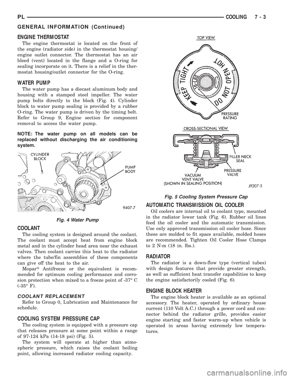
The water pump has a diecast aluminum body and
housing with a stamped steel impeller. The water
pump bolts directly to the block (Fig. 4). Cylinder
block to water pump sealing is provided by a rubber
O-ring. The water pump is driven by the timing belt.
Refer to Group 9, Engine section for component
removal to access the water pump.
NOTE: The water pump on all models can be
replaced without discharging the air conditioning
system.
COOLANT
The cooling system is designed around the coolant.
The coolant must accept heat from engine block
metal and in the cylinder head area near the exhaust
valves. Then coolant carries this heat to the radiator
where the tube/fin assemblies of these components
can give off the heat to the air.
MopartAntifreeze or the equivalent is recom-
mended for optimum cooling performance and corro-
sion protection when mixed to a freeze point of -37É C
(-35É F).
COOLANT REPLACEMENT
Refer to Group 0, Lubrication and Maintenance for
schedule.
COOLING SYSTEM PRESSURE CAP
The cooling system is equipped with a pressure cap
that releases pressure at some point within a range
of 97-124 kPa (14-18 psi) (Fig. 5).
The system will operate at higher than atmo-
spheric pressure, which raises the coolant boiling
point, allowing increased radiator cooling capacity.
AUTOMATIC TRANSMISSION OIL COOLER
Oil coolers are internal oil to coolant type, mounted
in the radiator lower tank (Fig. 6). Rubber oil lines
feed the oil cooler and the automatic transmission.
Use only approved transmission oil cooler hose. Since
these are molded to fit space available, molded hoses
are recommended. Tighten Oil Cooler Hose Clamps
to 2 N´m (18 in. lbs.).
RADIATOR
The radiator is a down-flow type (vertical tubes)
with design features that provide greater strength,
as well as sufficient heat transfer capabilities to keep
the engine satisfactorily cooled (Fig. 6).
ENGINE BLOCK HEATER
The engine block heater is available as an optional
accessory. The heater, operated by ordinary house
current (110 Volt A.C.) through a power cord and con-
nector behind the radiator grille, provides easier
engine starting and faster warm-up when vehicle is
operated in areas having extremely low tempera-
tures.
Fig. 4 Water Pump
Fig. 5 Cooling System Pressure Cap
PLCOOLING 7 - 3
GENERAL INFORMATION (Continued)
Page 199 of 1200
WATER PUMP
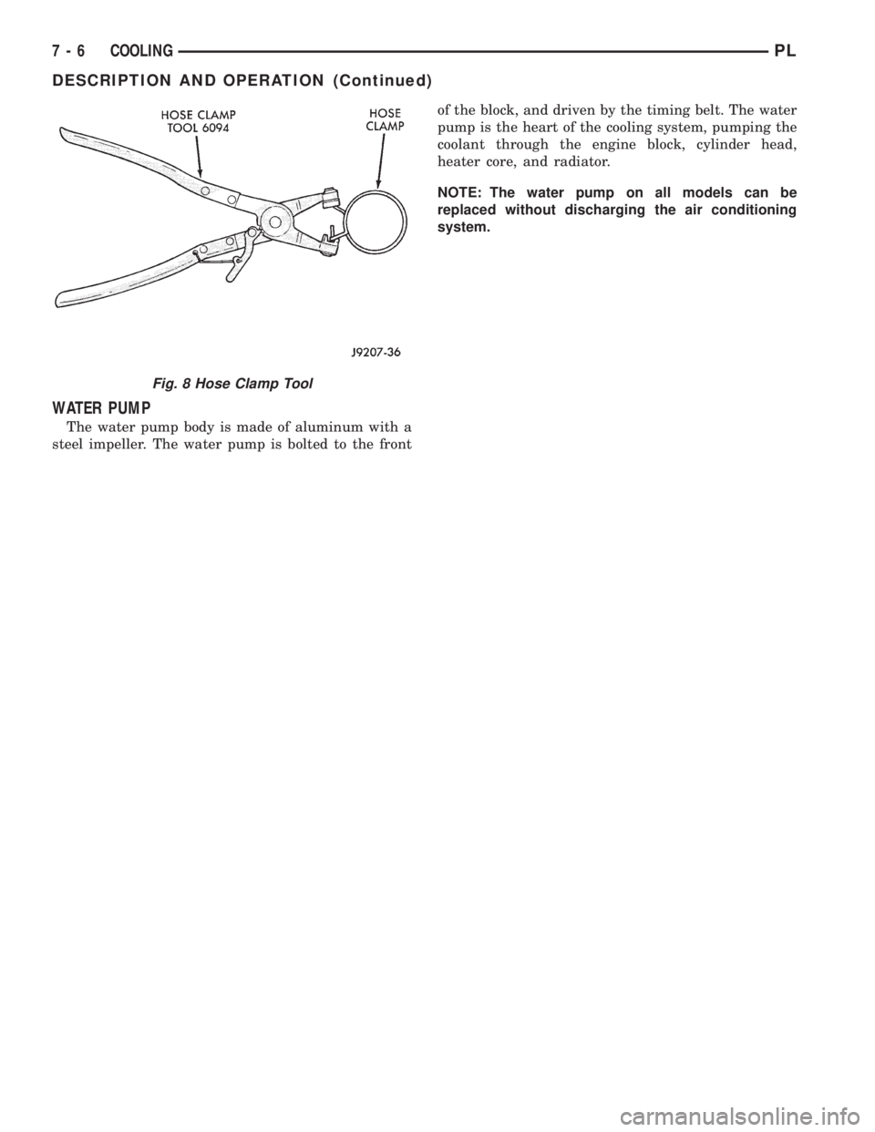
The water pump body is made of aluminum with a
steel impeller. The water pump is bolted to the frontof the block, and driven by the timing belt. The water
pump is the heart of the cooling system, pumping the
coolant through the engine block, cylinder head,
heater core, and radiator.
NOTE: The water pump on all models can be
replaced without discharging the air conditioning
system.
Fig. 8 Hose Clamp Tool
7 - 6 COOLINGPL
DESCRIPTION AND OPERATION (Continued)
Page 210 of 1200
COOLING SYSTEMÐREFILLING
First clean system to remove old glycol, see Cooling
System Cleaning.
Fill system using antifreeze described in Coolant
section. Fill 50 percent of capacity with 100 percent
glycol. Then complete filling system with water.
Continue filling system until full, this provides bet-
ter heater performance.Be careful not to spill
coolant on drive belts or the generator.
Fill coolant reserve system to at least the FULL
mark with 50/50 solution. It may be necessary to add
coolant to the reserve tank after three or four warm-
up/cool down cycles to maintain coolant level between
the FULL and ADD marks; if any trapped air was
removed from the system.
REMOVAL AND INSTALLATION
WATER PUMP
REMOVAL
(1) Raise vehicle on a hoist. Remove right inner
splash shield.
(2) Remove accessory drive belts and power steer-
ing pump. Refer to Accessory Drive Belt service in
this section.
(3) Drain cooling system. Refer to Cooling System
Draining in this section.
(4) Support engine from the bottom and remove
right engine mount.
(5) Remove power steering pump bracket bolts and
set pump and bracket assembly aside. Power steering
lines do not need to be disconnected.
(6) Remove right engine mount bracket.
(7) Remove timing belt and timing belt tensioner.
Refer to Group 9, Engine for procedure.
(8) Remove camshaft sprockets and inner timing
belt cover. Refer to Group 9, Engine for procedure.(9) Remove water pump attaching screws to engine
(Fig. 14).
INSTALLATION
(1) Install new O-ring gasket in water pump body
O-ring groove (Fig. 15). Use small dabs of Mopart
Silicone Rubber Adhesive Sealant around the water
pump body to secure O-ring in place during installa-
tion.
CAUTION: Make sure O-ring gasket is properly
seated in water pump groove before tightening
screws. An improperly located O-ring may cause
damage to the O-ring and cause a coolant leak.
(2) Assemble pump body to block and tighten
screws to 12 N´m (105 in. lbs.). Pressurize cooling
system to 15 psi with pressure tester and check
water pump shaft seal and O-ring for leaks.
(3) Rotate pump by hand to check for freedom of
movement.
(4) Install inner timing belt cover.
(5) Install timing belt. Refer to Group 9, Engine
for procedures.
(6) Install right engine mount bracket and engine
mount. Refer to Group 9, Engine for procedure.
(7) Fill cooling system. SeeCooling System
Refilling.
(8) Install power steering pump and accessory
drive belts, Refer to Accessory Drive Belts, in this
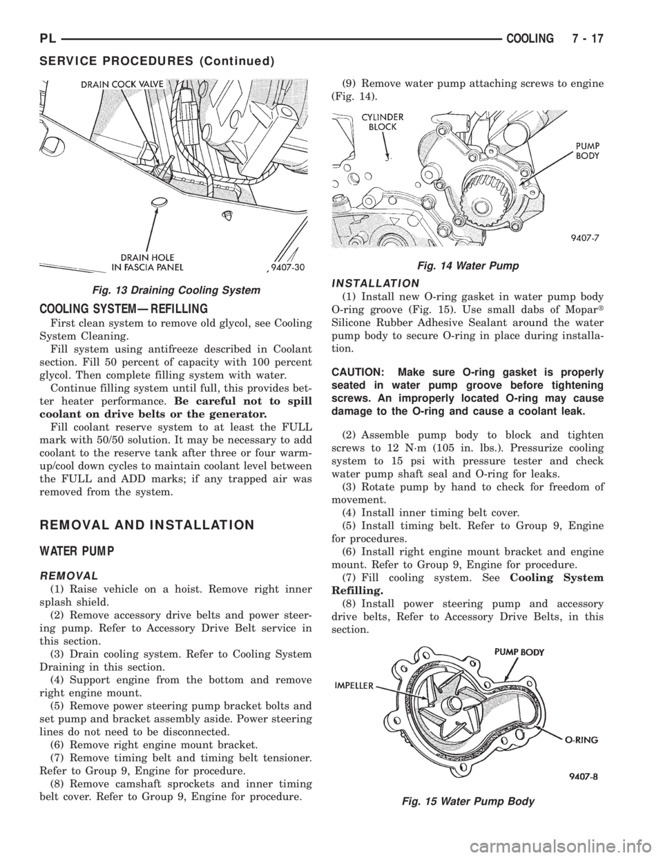
section.Fig. 13 Draining Cooling System
Fig. 14 Water Pump
Fig. 15 Water Pump Body
PLCOOLING 7 - 17
SERVICE PROCEDURES (Continued)
Page 211 of 1200
(9) Perform camshaft and crankshaft timing
relearn procedure as follows:
²Connect the DRB scan tool to the data link
(diagnostic) connector. This connector is located in
the passenger compartment; at the lower edge of
instrument panel; near the steering column.
²Turn the ignition switch on and access the ªmis-
cellaneousº screen.
²Select ªre-learn cam/crankº option and follow
directions on DRB screen.
WATER PUMP INLET TUBE
The inlet tube connects the water pump to the
radiator and heater core. This tube is sealed by a
O-ring and held in place by fasteners to the block.
REMOVAL
CAUTION: Do not use any sharp tools to remove
hoses from inlet tube. This may cause the tube to
leak.
(1) Drain cooling system. Refer to procedure out-
lined in this section.
(2) Remove upper radiator hose to access the hose
connections at the inlet tube.
(3) Remove lower radiator hose and heater hose
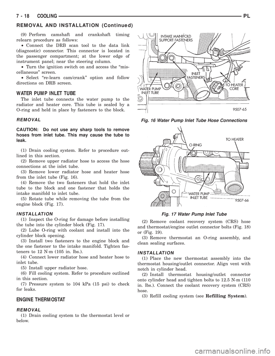
from the inlet tube (Fig. 16).
(4) Remove the two fasteners that hold the inlet
tube to the block and one fastener that holds the
intake manifold to inlet tube.
(5) Rotate tube while removing the tube from the
engine block (Fig. 17).
INSTALLATION
(1) Inspect the O-ring for damage before installing
the tube into the cylinder block (Fig. 17).
(2) Lube O-ring with coolant and install into the
cylinder block opening.
(3) Install two fasteners to the engine block and
the one fastener to the intake manifold. Tighten fas-
teners to 12 N´m (105 in. lbs.).
(4) Connect lower radiator hose and heater hose to
inlet tube.
(5) Install upper radiator hose.
(6) Fill cooling system. Refer to procedure outlined
in this section.
(7) Pressure system to 104 kPa (15 psi) to check
for leaks.
ENGINE THERMOSTAT
REMOVAL
(1) Drain cooling system to the thermostat level or
below.(2) Remove coolant recovery system (CRS) hose
and thermostat/engine outlet connector bolts (Fig. 18)
or (Fig. 19).
(3) Remove thermostat an O-ring assembly, and
clean sealing surfaces.
INSTALLATION
(1) Place the new thermostat assembly into the
thermostat housing/outlet connector. Align vent with
notch in cylinder head.
(2) Install thermostat housing/outlet connector
onto cylinder head and tighten bolts to 12.5 N´m (110
in. lbs.). Connect the coolant recovery system (CRS)
hose.
(3) Refill cooling system (seeRefilling System).
Fig. 16 Water Pump Inlet Tube Hose Connections
Fig. 17 Water Pump Inlet Tube
7 - 18 COOLINGPL
REMOVAL AND INSTALLATION (Continued)
Page 250 of 1200
IGNITION SYSTEM
CONTENTS
page page
GENERAL INFORMATION
INTRODUCTION......................... 1
DESCRIPTION AND OPERATION
AUTOMATIC SHUTDOWN RELAY............ 3
CAMSHAFT POSITION SENSOR............. 4
COMBINATION ENGINE COOLANT
TEMPERATURE SENSOR................. 5
CRANKSHAFT POSITION SENSOR........... 4
ELECTRONIC IGNITION COILS.............. 3
IGNITION INTERLOCK.................... 7
IGNITION SWITCH....................... 7
IGNITION SYSTEM....................... 1
INTAKE AIR TEMPERATURE SENSOR........ 6
KNOCK SENSOR......................... 6
LOCK KEY CYLINDER..................... 7
MANIFOLD ABSOLUTE PRESSURE SENSOR
(MAP)............................... 6
POWERTRAIN CONTROL MODULE.......... 2
SPARK PLUG CABLES.................... 2
SPARK PLUGS.......................... 2
THROTTLE POSITION SENSOR (TPS)........ 6
DIAGNOSIS AND TESTING
CAMSHAFT POSITION SENSOR AND
CRANKSHAFT POSITION SENSOR......... 9
CHECK COIL TEST....................... 8
ENGINE COOLANT TEMPERATURE SENSOR . . . 9
FAILURE TO START TESTÐ2.0/2.4L......... 8
IGNITION TIMING PROCEDURE............. 9
INTAKE AIR TEMPERATURE SENSOR........ 9
MANIFOLD ABSOLUTE PRESSURE (MAP)
SENSOR TEST......................... 9
SPARK PLUG CONDITION................ 10TESTING FOR SPARK AT COILÐ2.0/2.4L..... 7
THROTTLE POSITION SENSOR............. 9
REMOVAL AND INSTALLATION
AUTOMATIC SHUTDOWN RELAY........... 13
CAMSHAFT POSITION SENSORÐDOHC..... 14
CAMSHAFT POSITION SENSORÐSOHC..... 13
COMBINATION ENGINE COOLANT
TEMPERATURE SENSORÐDOHC........ 15
COMBINATION ENGINE COOLANT
TEMPERATURE SENSORÐSOHC......... 15
CRANKSHAFT POSITION SENSOR.......... 15
IGNITION COIL......................... 13
IGNITION INTERLOCK................... 18
IGNITION SWITCH...................... 16
LOCK CYLINDER HOUSING............... 18
LOCK KEY CYLINDER.................... 17
MAP/IAT SENSORÐDOHC................ 16
MAP/IAT SENSORÐSOHC................ 16
POWERTRAIN CONTROL MODULE (PCM) . . . 12
SPARK PLUG CABLE SERVICE............ 13
SPARK PLUG SERVICE.................. 12
SPARK PLUG TUBES.................... 13
THROTTLE POSITION SENSOR............ 16
SPECIFICATIONS
FIRING ORDERÐ2.0L................... 18
IGNITION COIL......................... 19
SPARK PLUG CABLE RESISTANCEÐDOHC . . 18
SPARK PLUG CABLE RESISTANCEÐSOHC . . . 18
SPARK PLUG.......................... 19
TORQUE SPECIFICATION................. 18
VECI LABEL........................... 18
GENERAL INFORMATION
INTRODUCTION
This section describes the electronic ignition sys-
tem for the 2.0L engines used in Neon vehicles.
The On-Board Diagnostics Section in Group 25
describes diagnostic trouble codes.
Group 0, Lubrication and Maintenance, contains
general maintenance information for ignition relateditems. The Owner's Manual also contains mainte-
nance information.DESCRIPTION AND OPERATION
IGNITION SYSTEM
Ignition system operation and diagnostics, are
identical for 2.0L Single Overhead Cam (SOHC) and
2.0L Duel Overhead Cam (DOHC) engines.
PLIGNITION SYSTEM 8D - 1
Page 251 of 1200
The major difference between the two engines is
component location which affects the ignition system
service procedures. There are various sensors that
are in different locations due to a different cylinder
head and intake manifold.
The 2.0L engines use a fixed ignition timing sys-
tem. The distributorless electronic ignition system is
referred to as the Direct Ignition System (DIS).
Basic ignition timing is not adjustable.The
Powertrain Control Module (PCM) determines spark
advance. The system's three main components are
the coil pack, crankshaft position sensor, and cam-
shaft position sensor.
POWERTRAIN CONTROL MODULE
The Powertrain Control Module (PCM) controls the
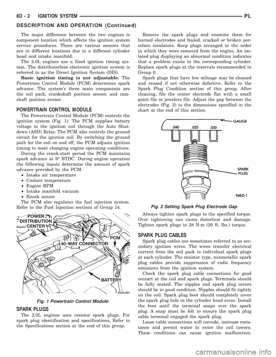
ignition system (Fig. 1). The PCM supplies battery
voltage to the ignition coil through the Auto Shut-
down (ASD) Relay. The PCM also controls the ground
circuit for the ignition coil. By switching the ground
path for the coil on and off, the PCM adjusts ignition
timing to meet changing engine operating conditions.
During the crank-start period the PCM maintains
spark advance at 9É BTDC. During engine operation
the following inputs determine the amount of spark
advance provided by the PCM.
²Intake air temperature
²Coolant temperature
²Engine RPM
²Intake manifold vacuum
²Knock sensor
The PCM also regulates the fuel injection system.
Refer to the Fuel Injection sections of Group 14.
SPARK PLUGS
The 2.0L engines uses resistor spark plugs. For
spark plug identification and specifications, Refer to
the Specifications section at the end of this group.Remove the spark plugs and examine them for
burned electrodes and fouled, cracked or broken por-
celain insulators. Keep plugs arranged in the order
in which they were removed from the engine. An iso-
lated plug displaying an abnormal condition indicates
that a problem exists in the corresponding cylinder.
Replace spark plugs at the intervals recommended in
Group 0.
Spark plugs that have low mileage may be cleaned
and reused if not otherwise defective. Refer to the
Spark Plug Condition section of this group. After
cleaning, file the center electrode flat with a small
point file or jewelers file. Adjust the gap between the
electrodes (Fig. 2) to the dimensions specified in the
chart at the end of this section.
Always tighten spark plugs to the specified torque.
Over tightening can cause distortion and damage.
Tighten spark plugs to 28 N´m (20 ft. lbs.) torque.
SPARK PLUG CABLES
Spark plug cables are sometimes referred to as sec-
ondary ignition wires. The wires transfer electrical
current from the coil pack to individual spark plugs
at each cylinder. The resistor type, nonmetallic spark
plug cables provide suppression of radio frequency
emissions from the ignition system.
Check the spark plug cable connections for good
contact at the coil and spark plugs. Terminals should
be fully seated. The nipples and spark plug covers
should be in good condition. Nipples should fit tightly
on the coil. Spark plug boot should completely cover
the spark plug hole in the cylinder head cover. Install
the boot until the terminal snaps over the spark
plug. A snap must be felt to ensure the spark plug
cable terminal engaged the spark plug.
Loose cable connections will corrode, increase resis-
tance and permit water to enter the coil towers.
These conditions can cause ignition malfunction.
Fig. 1 Powertrain Control Module
Fig. 2 Setting Spark Plug Electrode Gap
8D - 2 IGNITION SYSTEMPL
DESCRIPTION AND OPERATION (Continued)
Page 252 of 1200
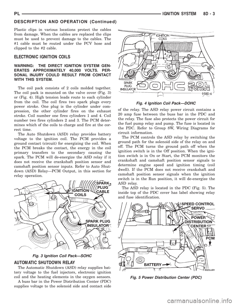
Plastic clips in various locations protect the cables
from damage. When the cables are replaced the clips
must be used to prevent damage to the cables. The
#1 cable must be routed under the PCV hose and
clipped to the #2 cable.
ELECTRONIC IGNITION COILS
WARNING: THE DIRECT IGNITION SYSTEM GEN-
ERATES APPROXIMATELY 40,000 VOLTS. PER-
SONAL INJURY COULD RESULT FROM CONTACT
WITH THIS SYSTEM.
The coil pack consists of 2 coils molded together.
The coil pack is mounted on the valve cover (Fig. 3)
or (Fig. 4). High tension leads route to each cylinder
from the coil. The coil fires two spark plugs every
power stroke. One plug is the cylinder under com-
pression, the other cylinder fires on the exhaust
stroke. Coil number one fires cylinders 1 and 4. Coil
number two fires cylinders 2 and 3. The PCM deter-
mines which of the coils to charge and fire at the cor-
rect time.
The Auto Shutdown (ASD) relay provides battery
voltage to the ignition coil. The PCM provides a
ground contact (circuit) for energizing the coil. When
the PCM breaks the contact, the energy in the coil
primary transfers to the secondary causing the
spark. The PCM will de-energize the ASD relay if it
does not receive the crankshaft position sensor and
camshaft position sensor inputs. Refer to Auto Shut-
down (ASD) RelayÐPCM Output, in this section for
relay operation.
AUTOMATIC SHUTDOWN RELAY
The Automatic Shutdown (ASD) relay supplies bat-
tery voltage to the fuel injectors, electronic ignition
coil and the heating elements in the oxygen sensors.
A buss bar in the Power Distribution Center (PDC)
supplies voltage to the solenoid side and contact sideof the relay. The ASD relay power circuit contains a
20 amp fuse between the buss bar in the PDC and
the relay. The fuse also protects the power circuit for
the fuel pump relay and pump. The fuse is located in
the PDC. Refer to Group 8W, Wiring Diagrams for
circuit information.
The PCM controls the ASD relay by switching the
ground path for the solenoid side of the relay on and
off. The PCM turns the ground path off when the
ignition switch is in the Off position. When the igni-
tion switch is in On or Start, the PCM monitors the
crankshaft and camshaft position sensor signals to
determine engine speed and ignition timing (coil
dwell). If the PCM does not receive crankshaft and
camshaft position sensor signals when the ignition
switch is in the Run position, it will de-energize the
ASD relay.
The ASD relay is located in the PDC (Fig. 5). The
inside top of the PDC cover has label showing relay
and fuse identification.
Fig. 3 Ignition Coil PackÐSOHC
Fig. 4 Ignition Coil PackÐDOHC
Fig. 5 Power Distribution Center (PDC)
PLIGNITION SYSTEM 8D - 3
DESCRIPTION AND OPERATION (Continued)
Page 253 of 1200
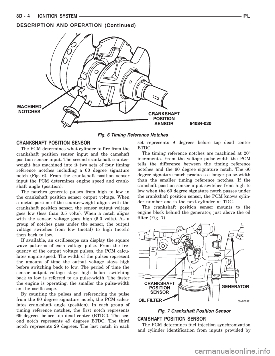
CRANKSHAFT POSITION SENSOR
The PCM determines what cylinder to fire from the
crankshaft position sensor input and the camshaft
position sensor input. The second crankshaft counter-
weight has machined into it two sets of four timing
reference notches including a 60 degree signature
notch (Fig. 6). From the crankshaft position sensor
input the PCM determines engine speed and crank-
shaft angle (position).
The notches generate pulses from high to low in
the crankshaft position sensor output voltage. When
a metal portion of the counterweight aligns with the
crankshaft position sensor, the sensor output voltage
goes low (less than 0.5 volts). When a notch aligns
with the sensor, voltage goes high (5.0 volts). As a
group of notches pass under the sensor, the output
voltage switches from low (metal) to high (notch)
then back to low.
If available, an oscilloscope can display the square
wave patterns of each voltage pulse. From the fre-
quency of the output voltage pulses, the PCM calcu-
lates engine speed. The width of the pulses represent
the amount of time the output voltage stays high
before switching back to low. The period of time the
sensor output voltage stays high before switching
back to low is referred to as pulse-width. The faster
the engine is operating, the smaller the pulse-width
on the oscilloscope.
By counting the pulses and referencing the pulse
from the 60 degree signature notch, the PCM calcu-
lates crankshaft angle (position). In each group of
timing reference notches, the first notch represents
69 degrees before top dead center (BTDC). The sec-
ond notch represents 49 degrees BTDC. The third
notch represents 29 degrees. The last notch in eachset represents 9 degrees before top dead center
BTDC.
The timing reference notches are machined at 20É
increments. From the voltage pulse-width the PCM
tells the difference between the timing reference
notches and the 60 degree signature notch. The 60
degree signature notch produces a longer pulse-width
than the smaller timing reference notches. If the
camshaft position sensor input switches from high to
low when the 60 degree signature notch passes under
the crankshaft position sensor, the PCM knows cylin-
der number one is the next cylinder at TDC.
The crankshaft position sensor mounts to the
engine block behind the generator, just above the oil
filter (Fig. 7).
CAMSHAFT POSITION SENSOR
The PCM determines fuel injection synchronization
and cylinder identification from inputs provided by
Fig. 6 Timing Reference Notches
Fig. 7 Crankshaft Position Sensor
8D - 4 IGNITION SYSTEMPL
DESCRIPTION AND OPERATION (Continued)