DODGE NEON 2000 Service Repair Manual
Manufacturer: DODGE, Model Year: 2000, Model line: NEON, Model: DODGE NEON 2000Pages: 1285, PDF Size: 29.42 MB
Page 1251 of 1285
(1) Discharge refrigerant system using recovery/re-
cycling equipment if charge is present.
(2) Disconnect refrigerant lines from A/C compres-
sor. Cap the open lines to prevent moisture from
entering system.
(3) Remove compressor from vehicle.
(4) From suction port on top of compressor, drain
lubricant from compressor.
(5) Add system capacity minus the capacity of
components that have not been replaced. Refer to the
Lubricant Capacity Chart. Add lubricant through the
suction port on compressor. This is not to exceed 180
ml (6.10 oz.) in total.
(6) Install compressor and connect refrigerant
lines. Then evacuate and charge refrigerant system.
SYSTEM LEAK CHECKING
WARNING: R-134a SERVICE EQUIPMENT OR VEHI-
CLE A/C SYSTEM SHOULD NOT BE PRESSURE
TESTED OR LEAK TESTED WITH COMPRESSED
AIR. MIXTURE OF AIR and R-134a CAN BE COM-
BUSTIBLE AT ELEVATED PRESSURES. THESE MIX-
TURES ARE POTENTIALLY DANGEROUS AND MAY
RESULT IN FIRE OR EXPLOSION CAUSING INJURY
OR PROPERTY DAMAGE.
AVOID BREATHING A/C REFRIGERANT AND
LUBRICANT VAPOR OR MIST. EXPOSURE MAY
IRRITATE EYES, NOSE AND THROAT. USE ONLY
APPROVED SERVICE EQUIPMENT MEETING SAE
REQUIREMENTS TO DISCHARGE R-134a SYSTEM.
IF ACCIDENTAL SYSTEM DISCHARGE OCCURS,
VENTILATE WORK AREA BEFORE RESUMING SER-
VICE.
If the A/C system is not cooling properly, determine
if the refrigerant system is fully charged with
R-134a. This is accomplished by performing a system
Charge Level-Check or Fill. If while performing this
test A/C liquid line pressure is less than 345 kPa (50
psi) proceed to Empty Refrigerant System Leak Test.
If liquid line pressure is greater than 345 kPa (50
psi) proceed to low refrigerant level leak test. If the
refrigerant system is empty or low in refrigerant
charge, a leak at any line fitting or component seal is
likely. A review of the fittings, lines and components
for oily residue is an indication of the leak location.
To detect a leak in the refrigerant system, perform
one of the following procedures as indicated by the
symptoms.
EMPTY REFRIGERANT SYSTEM LEAK TEST
(1) Evacuate the refrigerant system to the lowest
degree of vacuum possible (approx. 28 in Hg.). Deter-
mine if the system holds a vacuum for 15 minutes. If
vacuum is held, a leak is probably not present. If sys-tem will not maintain vacuum level, proceed with
this procedure.
(2) Prepare a.284 Kg. (10 oz.) refrigerant charge to
be injected into the system.
(3) Connect and dispense.284 Kg. (10 oz.) of refrig-
erant into the evacuated refrigerant system.
(4) Proceed to Step 2 of Low Refrigerant Level
Leak Test.
LOW REFRIGERANT LEVEL LEAK TEST
(1) Determine if there is any (R-134a) refrigerant
in the system.
(2) Position the vehicle in a wind free work area.
This will aid in detecting small leaks.
(3) Bring the refrigerant system up to operating
temperature and pressure. This is done by allowing
the engine to run for five minutes with the system
set to the following:
²Transaxle in Park
²Engine Idling at 700 rpm
²A/C Controls Set in 100 percent outside air
²Blower switch in the high A/C position
²A/C in the ON position
²Open all windows
CAUTION: A leak detector designed for R-12 refrig-
erant (only) will not detect leaks in a R-134a refrig-
erant system.
(4) Shut off the vehicle and wait 2 to 7 minutes.
Then use an Electronic Leak Detector that is
designed to detect R-134a type refrigerant and search
for leaks. Fittings, lines, or components that appear
to be oily usually indicates a refrigerant leak. To
inspect the evaporator core for leaks, insert the leak
detector probe into the drain tube opening or a heat
duct. A R-134a dye is available to aid in leak detec-
tion, use only Chrysler approved refrigerant dye.
If a thorough leak check has been completed with-
out indication of a leak, proceed to System Charge
Level.
REMOVAL AND INSTALLATION
A/C FILTER/DRIER
The filter/drier is mounted in a rubber grommet on
the right side of the engine compartment. The refrig-
erant must be recovered from the A/C system before
replacing the filter/drier assembly.
WARNING: THE REFRIGERATION SYSTEM MUST
BE COMPLETELY RECOVERED BEFORE PRO-
CEEDING WITH THIS OPERATION.
24 - 20 HEATING AND AIR CONDITIONINGPL
SERVICE PROCEDURES (Continued)
Page 1252 of 1285
REMOVAL
(1) Disconnect liquid line from filter/drier.
(2) Disconnect liquid line on suction line assembly
from filter/drier.
(3) Pull filter/drier out of rubber grommet.
INSTALLATION
For installation, reverse the above procedures.
A/C SERVICE PORT VALVE CORES
REMOVAL
(1) Remove the valve caps (Fig. 4).
(2) Using a R-134a refrigerant recovery machine,
Remove the refrigerant from A/C system.
(3) Using a standard valve core tool, remove the
valve core.Be careful to prevent any dirt/debris
from entering the valve core opening or getting
on the replacement valve core.
INSTALLATION
(1) When assembling the new valve core into the
port, the core should be oiled with clean ND8 PAG
compressor oil.
CAUTION: A valve that is not fully seated can lead
to damage to the valve during evacuation and
charge. This can result in system refrigerant dis-
charge while uncoupling the charge adapters.
(2) Install valve core into port.
(3) Evacuate and charge the A/C system.
(4) Install the valve caps.
BLOWER MOTOR AND WHEEL ASSEMBLY
The blower motor is located on the bottom right
side of the unit housing. The blower motor can be
removed from the vehicle without having to remove
the unit housing assembly.
WITH AIR CONDITIONING
REMOVAL
(1) Remove right side scuff plate.
(2) Pull back carpet.
(3) Disconnect blower motor wiring connector.
(4) Remove blower motor retaining screws, and
lower blower motor assembly from unit housing (Fig.
20).
INSTALLATION
For installation, reverse the above procedures.
WITHOUT AIR CONDITIONING
REMOVAL
(1) Disconnect blower motor wiring connector.
(2) Grasp the blower motor while pulling down
tab. Turn approximately 1/8 turn counterclockwise
and remove blower motor assembly from unit hous-
ing (Fig. 21).
INSTALLATION
For installation, reverse the above procedures.
Fig. 20 Blower Motor Retaining Screws
1 ± BLOWER MOTOR
2 ± BLOWER MOTOR RETAINING SCREWS
3 ± BLOWER MOTOR WIRING
Fig. 21 Blower Motor Removal
1 ± BLOWER MODULE
2 ± BLOWER MOTOR
PLHEATING AND AIR CONDITIONING 24 - 21
REMOVAL AND INSTALLATION (Continued)
Page 1253 of 1285
BLOWER MOTOR RESISTOR
CAUTION: Stay clear of the blower motor and resis-
tor block (Hot). Do not operate the blower motor
with the resistor block removed.
REMOVAL
(1) Remove windshield wipers.
(2) Remove cowl top screen.
(3) Disconnect the resistor block wiring connector
(Fig. 22).
(4) Remove/unsnap resistor block from vehicle.
INSTALLATION
For installation, reverse the above procedures.
BLOWER MOTOR WHEEL
The blower motor wheel is only serviced with the
blower motor. The wheel and the motor are balanced
as an assembly. If the blower motor wheel requires
replacement, the blower motor must also be replaced.
Refer to blower motor for replacement procedure.
COMPRESSOR
CAUTION: Add only new lubricant when system
requires additional lubricant. Do not use old
reclaimed lubricant.
REMOVAL
The A/C compressor may be unbolted and reposi-
tioned without discharging the refrigerant system.
Discharging is not necessary if removing the com-
pressor clutch/coil assembly, engine, cylinder head, or
alternator.
WARNING: REFRIGERANT PRESSURES REMAIN
HIGH EVEN THOUGH THE ENGINE MAY BE
TURNED OFF. DO NOT TWIST OR KINK THE
REFRIGERANT LINES WHEN REMOVING A FULLY
CHARGED COMPRESSOR. SAFETY GLASSES
MUST BE WORN.
(1) Disconnect battery negative cable.
(2) Loosen and remove drive belts, refer to Group
7, Engine Cooling.
(3) Using a R-134a refrigerant recovery machine,
remove the refrigerant from A/C system. If the com-
pressor is being replaced.
(4) Disconnect compressor clutch wire lead.
(5) Remove refrigerant lines from compressor, if
necessary (Fig. 23).
(6) If system is left open place plug/cap over open
lines.
(7) Remove compressor attaching bolts (Fig. 24).
Fig. 22 Blower Motor Resistor Block
1 ± RESISTOR BLOCK
2 ± ELECTRICAL CONNECTOR
Fig. 23 A/C Compressor Lines
1 ± CONDENSER LIQUID LINE
2 ± SUCTION LINE
3 ± COMPRESSOR MANIFOLD SCREWS
4 ± COMPRESSOR
5 ± DISCHARGE LINE
24 - 22 HEATING AND AIR CONDITIONINGPL
REMOVAL AND INSTALLATION (Continued)
Page 1254 of 1285
(8) Remove compressor. If refrigerant lines were
not removed, lift compressor/clutch assembly and tie
it to a suitable component.
INSTALLATION
For installation, reverse the above procedures.
²Tighten the compressor mounting bolts to 28
N´m (250 in lbs).
²Tighten the compressor lines to 12 N´m (108 in
lbs).
COMPRESSOR CLUTCH/COIL ASSEMBLY
Compressor assembly must be removed from
mounting. Although, refrigerant discharge is not nec-
essary.
REMOVAL
(1) Remove the compressor shaft bolt (Fig. 25). A
band type oil filter removal tool can be placed around
the clutch plate to aid in bolt removal.
(2) Tap the clutch plate with a plastic hammer and
remove clutch plate and shim(s) (Fig. 26).
NOTE: Use care not to lose any of the shim(s).CAUTION: Do not use screwdrivers between the
clutch plate assembly and pulley to remove front
plate as this may damage the front plate assembly.
Fig. 24 A/C Compressor Mounting Bolts
1 ± A/C COMPRESSOR
2 ± MOUNTING BOLTS
3 ± LOWER FRONT STRUT-TO-ENGINE BRACKET
Fig. 25 Compressor Shaft Bolt and Clutch Plate
1 ± COMPRESSOR SHAFT BOLT
2 ± COMPRESSOR CLUTCH PLATE
Fig. 26 Clutch Plate and Shim(s)
1 ± COMPRESSOR SHAFT
2 ± CLUTCH PLATE
3 ± CLUTCH PLATE SHIM
PLHEATING AND AIR CONDITIONING 24 - 23
REMOVAL AND INSTALLATION (Continued)
Page 1255 of 1285
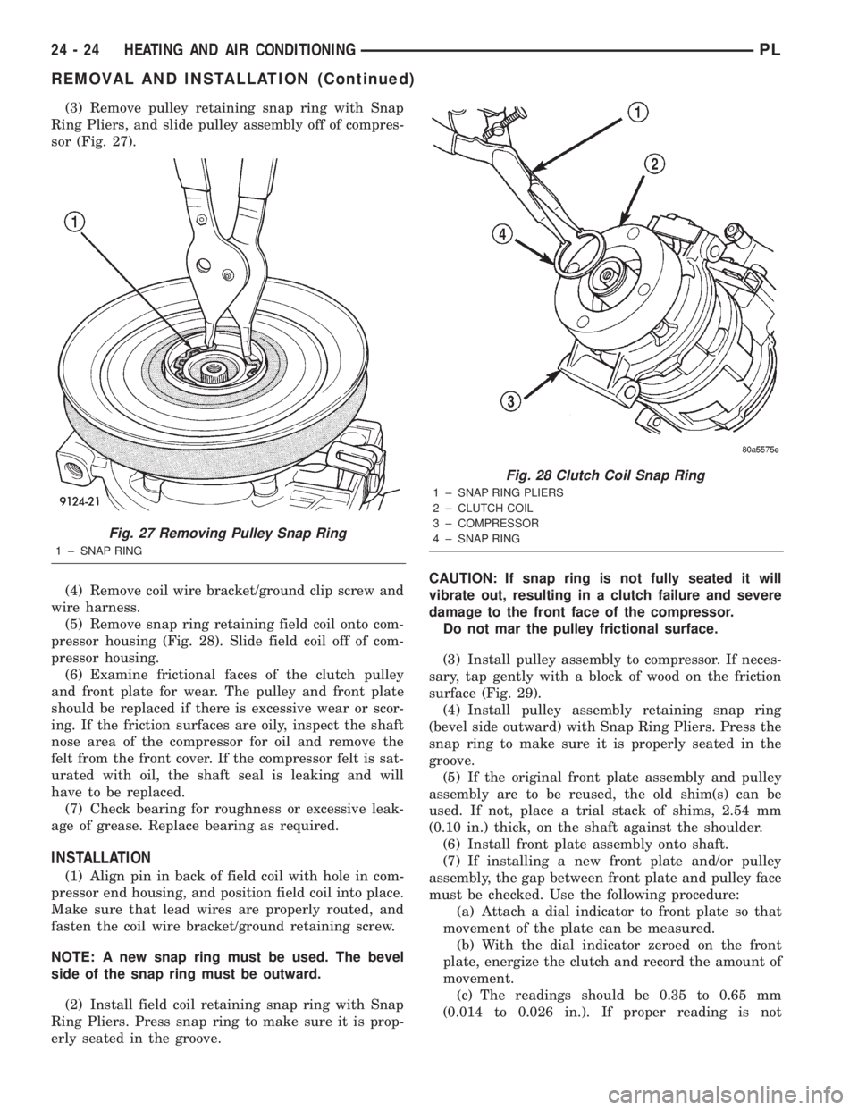
(3) Remove pulley retaining snap ring with Snap
Ring Pliers, and slide pulley assembly off of compres-
sor (Fig. 27).
(4) Remove coil wire bracket/ground clip screw and
wire harness.
(5) Remove snap ring retaining field coil onto com-
pressor housing (Fig. 28). Slide field coil off of com-
pressor housing.
(6) Examine frictional faces of the clutch pulley
and front plate for wear. The pulley and front plate
should be replaced if there is excessive wear or scor-
ing. If the friction surfaces are oily, inspect the shaft
nose area of the compressor for oil and remove the
felt from the front cover. If the compressor felt is sat-
urated with oil, the shaft seal is leaking and will
have to be replaced.
(7) Check bearing for roughness or excessive leak-
age of grease. Replace bearing as required.
INSTALLATION
(1) Align pin in back of field coil with hole in com-
pressor end housing, and position field coil into place.
Make sure that lead wires are properly routed, and
fasten the coil wire bracket/ground retaining screw.
NOTE: A new snap ring must be used. The bevel
side of the snap ring must be outward.
(2) Install field coil retaining snap ring with Snap
Ring Pliers. Press snap ring to make sure it is prop-
erly seated in the groove.CAUTION: If snap ring is not fully seated it will
vibrate out, resulting in a clutch failure and severe
damage to the front face of the compressor.
Do not mar the pulley frictional surface.
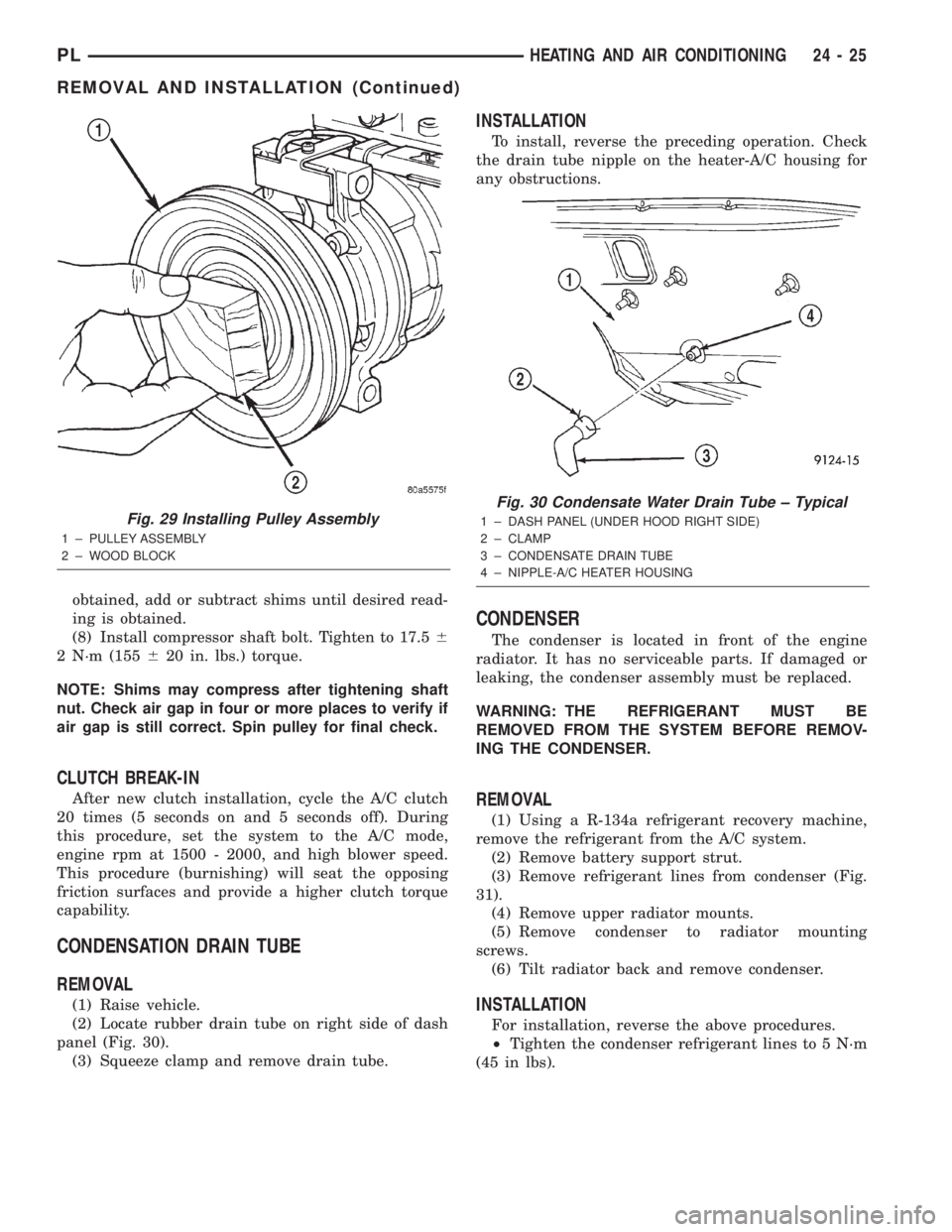
(3) Install pulley assembly to compressor. If neces-
sary, tap gently with a block of wood on the friction
surface (Fig. 29).
(4) Install pulley assembly retaining snap ring
(bevel side outward) with Snap Ring Pliers. Press the
snap ring to make sure it is properly seated in the
groove.
(5) If the original front plate assembly and pulley
assembly are to be reused, the old shim(s) can be
used. If not, place a trial stack of shims, 2.54 mm
(0.10 in.) thick, on the shaft against the shoulder.
(6) Install front plate assembly onto shaft.
(7) If installing a new front plate and/or pulley
assembly, the gap between front plate and pulley face
must be checked. Use the following procedure:
(a) Attach a dial indicator to front plate so that
movement of the plate can be measured.
(b) With the dial indicator zeroed on the front
plate, energize the clutch and record the amount of
movement.
(c) The readings should be 0.35 to 0.65 mm
(0.014 to 0.026 in.). If proper reading is not
Fig. 27 Removing Pulley Snap Ring
1 ± SNAP RING
Fig. 28 Clutch Coil Snap Ring
1 ± SNAP RING PLIERS
2 ± CLUTCH COIL
3 ± COMPRESSOR
4 ± SNAP RING
24 - 24 HEATING AND AIR CONDITIONINGPL
REMOVAL AND INSTALLATION (Continued)
Page 1256 of 1285
obtained, add or subtract shims until desired read-
ing is obtained.
(8) Install compressor shaft bolt. Tighten to 17.56
2 N´m (155620 in. lbs.) torque.
NOTE: Shims may compress after tightening shaft
nut. Check air gap in four or more places to verify if
air gap is still correct. Spin pulley for final check.
CLUTCH BREAK-IN
After new clutch installation, cycle the A/C clutch
20 times (5 seconds on and 5 seconds off). During
this procedure, set the system to the A/C mode,
engine rpm at 1500 - 2000, and high blower speed.
This procedure (burnishing) will seat the opposing
friction surfaces and provide a higher clutch torque
capability.
CONDENSATION DRAIN TUBE
REMOVAL
(1) Raise vehicle.
(2) Locate rubber drain tube on right side of dash
panel (Fig. 30).
(3) Squeeze clamp and remove drain tube.
INSTALLATION
To install, reverse the preceding operation. Check
the drain tube nipple on the heater-A/C housing for
any obstructions.
CONDENSER
The condenser is located in front of the engine
radiator. It has no serviceable parts. If damaged or
leaking, the condenser assembly must be replaced.
WARNING: THE REFRIGERANT MUST BE
REMOVED FROM THE SYSTEM BEFORE REMOV-
ING THE CONDENSER.
REMOVAL
(1) Using a R-134a refrigerant recovery machine,
remove the refrigerant from the A/C system.
(2) Remove battery support strut.
(3) Remove refrigerant lines from condenser (Fig.
31).
(4) Remove upper radiator mounts.
(5) Remove condenser to radiator mounting
screws.
(6) Tilt radiator back and remove condenser.
INSTALLATION
For installation, reverse the above procedures.
²Tighten the condenser refrigerant lines to 5 N´m
(45 in lbs).
Fig. 29 Installing Pulley Assembly
1 ± PULLEY ASSEMBLY
2 ± WOOD BLOCK
Fig. 30 Condensate Water Drain Tube ± Typical
1 ± DASH PANEL (UNDER HOOD RIGHT SIDE)
2 ± CLAMP
3 ± CONDENSATE DRAIN TUBE
4 ± NIPPLE-A/C HEATER HOUSING
PLHEATING AND AIR CONDITIONING 24 - 25
REMOVAL AND INSTALLATION (Continued)
Page 1257 of 1285
DISCHARGE LINE
WARNING: THE REFRIGERANT SYSTEM MUST BE
RECOVERED BEFORE SERVICING ANY PART OF
THE REFRIGERANT SYSTEM.
REMOVAL
(1) Using a R-134a refrigerant recovery machine,
remove the refrigerant from A/C system.
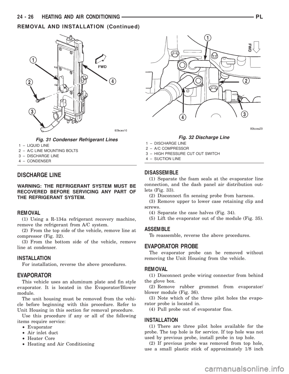
(2) From the top side of the vehicle, remove line at
compressor (Fig. 32).
(3) From the bottom side of the vehicle, remove
line at condenser.
INSTALLATION
For installation, reverse the above procedures.
EVAPORATOR
This vehicle uses an aluminum plate and fin style
evaporator. It is located in the Evaporator/Blower
module.
The unit housing must be removed from the vehi-
cle before beginning with this procedure. Refer to
Unit Housing in this section for removal procedure.
Use this procedure if any or all of the following
items require service:
²Evaporator
²Air inlet duct
²Heater Core
²Heating and Air Conditioning
DISASSEMBLE
(1) Separate the foam seals at the evaporator line
connection, and the dash panel air distribution out-
lets (Fig. 33).
(2) Disconnect fin sensing probe from harness.
(3) Remove upper to lower case retaining clip and
screws.
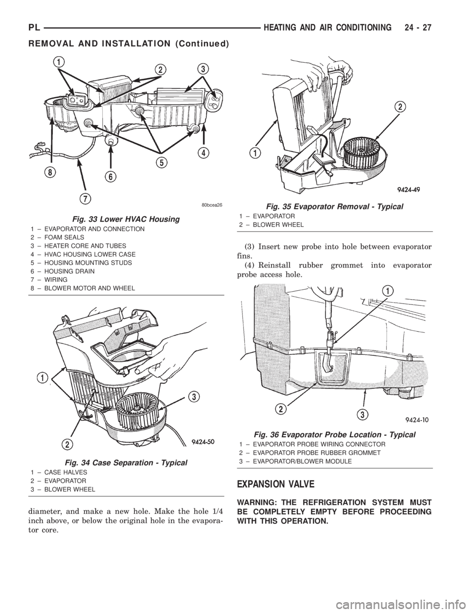
(4) Separate the case halves (Fig. 34).
(5) Lift the evaporator out of the module (Fig. 35).
ASSEMBLE
To reassemble, reverse the above procedures.
EVAPORATOR PROBE
The evaporator probe can be removed without
removing the Unit Housing from the vehicle.
REMOVAL
(1) Disconnect probe wiring connector from behind
the glove box.
(2) Remove rubber grommet from evaporator/
blower module (Fig. 36).
(3) Note which of the three pilot holes the evapo-
rator probe is located in.
(4) Pull probe out of evaporator fins.
INSTALLATION
(1) There are three pilot holes available for the
probe. The top hole is for service. If top hole was not
used by previous probe, install probe in top hole.
(2) If previous probe was removed from top hole,
use a small plastic stick of approximately 1/8 inch
Fig. 31 Condenser Refrigerant Lines
1 ± LIQUID LINE
2 ± A/C LINE MOUNTING BOLTS
3 ± DISCHARGE LINE
4 ± CONDENSER
Fig. 32 Discharge Line
1 ± DISCHARGE LINE
2 ± A/C COMPRESSOR
3 ± HIGH PRESSURE CUT OUT SWITCH
4 ± SUCTION LINE
24 - 26 HEATING AND AIR CONDITIONINGPL
REMOVAL AND INSTALLATION (Continued)
Page 1258 of 1285
diameter, and make a new hole. Make the hole 1/4
inch above, or below the original hole in the evapora-
tor core.(3) Insert new probe into hole between evaporator
fins.
(4) Reinstall rubber grommet into evaporator
probe access hole.
EXPANSION VALVE
WARNING: THE REFRIGERATION SYSTEM MUST
BE COMPLETELY EMPTY BEFORE PROCEEDING
WITH THIS OPERATION.
Fig. 33 Lower HVAC Housing
1 ± EVAPORATOR AND CONNECTION
2 ± FOAM SEALS
3 ± HEATER CORE AND TUBES
4 ± HVAC HOUSING LOWER CASE
5 ± HOUSING MOUNTING STUDS
6 ± HOUSING DRAIN
7 ± WIRING
8 ± BLOWER MOTOR AND WHEEL
Fig. 34 Case Separation - Typical
1 ± CASE HALVES
2 ± EVAPORATOR
3 ± BLOWER WHEEL
Fig. 35 Evaporator Removal - Typical
1 ± EVAPORATOR
2 ± BLOWER WHEEL
Fig. 36 Evaporator Probe Location - Typical
1 ± EVAPORATOR PROBE WIRING CONNECTOR
2 ± EVAPORATOR PROBE RUBBER GROMMET
3 ± EVAPORATOR/BLOWER MODULE
PLHEATING AND AIR CONDITIONING 24 - 27
REMOVAL AND INSTALLATION (Continued)
Page 1259 of 1285
REMOVAL
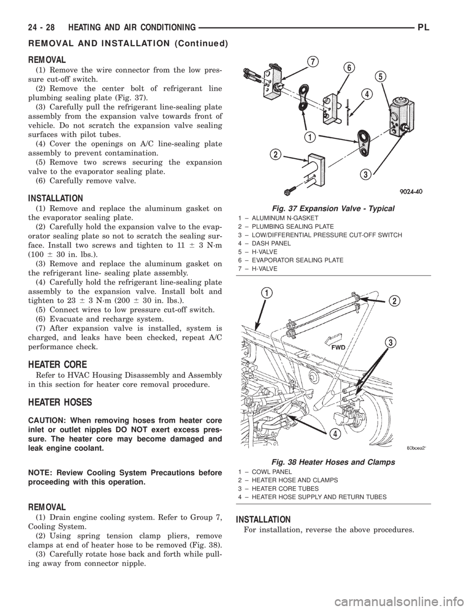
(1) Remove the wire connector from the low pres-
sure cut-off switch.
(2) Remove the center bolt of refrigerant line
plumbing sealing plate (Fig. 37).
(3) Carefully pull the refrigerant line-sealing plate
assembly from the expansion valve towards front of
vehicle. Do not scratch the expansion valve sealing
surfaces with pilot tubes.
(4) Cover the openings on A/C line-sealing plate
assembly to prevent contamination.
(5) Remove two screws securing the expansion
valve to the evaporator sealing plate.
(6) Carefully remove valve.
INSTALLATION
(1) Remove and replace the aluminum gasket on
the evaporator sealing plate.
(2) Carefully hold the expansion valve to the evap-
orator sealing plate so not to scratch the sealing sur-
face. Install two screws and tighten to 1163 N´m
(100630 in. lbs.).
(3) Remove and replace the aluminum gasket on
the refrigerant line- sealing plate assembly.
(4) Carefully hold the refrigerant line-sealing plate
assembly to the expansion valve. Install bolt and
tighten to 2363 N´m (200630 in. lbs.).
(5) Connect wires to low pressure cut-off switch.
(6) Evacuate and recharge system.
(7) After expansion valve is installed, system is
charged, and leaks have been checked, repeat A/C
performance check.
HEATER CORE
Refer to HVAC Housing Disassembly and Assembly
in this section for heater core removal procedure.
HEATER HOSES
CAUTION: When removing hoses from heater core
inlet or outlet nipples DO NOT exert excess pres-
sure. The heater core may become damaged and
leak engine coolant.
NOTE: Review Cooling System Precautions before
proceeding with this operation.
REMOVAL
(1) Drain engine cooling system. Refer to Group 7,
Cooling System.
(2) Using spring tension clamp pliers, remove
clamps at end of heater hose to be removed (Fig. 38).
(3) Carefully rotate hose back and forth while pull-
ing away from connector nipple.INSTALLATION
For installation, reverse the above procedures.
Fig. 37 Expansion Valve - Typical
1 ± ALUMINUM N-GASKET
2 ± PLUMBING SEALING PLATE
3 ± LOW/DIFFERENTIAL PRESSURE CUT-OFF SWITCH
4 ± DASH PANEL
5 ± H-VALVE
6 ± EVAPORATOR SEALING PLATE
7 ± H-VALVE
Fig. 38 Heater Hoses and Clamps
1 ± COWL PANEL
2 ± HEATER HOSE AND CLAMPS
3 ± HEATER CORE TUBES
4 ± HEATER HOSE SUPPLY AND RETURN TUBES
24 - 28 HEATING AND AIR CONDITIONINGPL
REMOVAL AND INSTALLATION (Continued)
Page 1260 of 1285
HIGH PRESSURE CUT OUT SWITCH
WARNING: THE REFRIGERANT MUST BE
REMOVED FROM THE SYSTEM BEFORE REMOV-
ING THE HIGH PRESSURE CUT OUT SWITCH.
REMOVAL
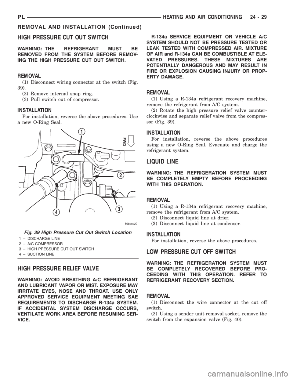
(1) Disconnect wiring connector at the switch (Fig.
39).
(2) Remove internal snap ring.
(3) Pull switch out of compressor.
INSTALLATION
For installation, reverse the above procedures. Use
a new O-Ring Seal.
HIGH PRESSURE RELIEF VALVE
WARNING: AVOID BREATHING A/C REFRIGERANT
AND LUBRICANT VAPOR OR MIST. EXPOSURE MAY
IRRITATE EYES, NOSE AND THROAT. USE ONLY
APPROVED SERVICE EQUIPMENT MEETING SAE
REQUIREMENTS TO DISCHARGE R-134a SYSTEM.
IF ACCIDENTAL SYSTEM DISCHARGE OCCURS,
VENTILATE WORK AREA BEFORE RESUMING SER-
VICE.R-134a SERVICE EQUIPMENT OR VEHICLE A/C
SYSTEM SHOULD NOT BE PRESSURE TESTED OR
LEAK TESTED WITH COMPRESSED AIR. MIXTURE
OF AIR and R-134a CAN BE COMBUSTIBLE AT ELE-
VATED PRESSURES. THESE MIXTURES ARE
POTENTIALLY DANGEROUS AND MAY RESULT IN
FIRE OR EXPLOSION CAUSING INJURY OR PROP-
ERTY DAMAGE.
REMOVAL
(1) Using a R-134a refrigerant recovery machine,
remove the refrigerant from A/C system.
(2) Rotate the high pressure relief valve counter-
clockwise and separate relief valve from the compres-
sor (Fig. 39).
INSTALLATION
For installation, reverse the above procedures
using a new O-Ring Seal. Evacuate and charge the
refrigerant system.
LIQUID LINE
WARNING: THE REFRIGERATION SYSTEM MUST
BE COMPLETELY EMPTY BEFORE PROCEEDING
WITH THIS OPERATION.
REMOVAL
(1) Using a R-134a refrigerant recovery machine,
remove the refrigerant from A/C system.
(2) Disconnect liquid line at drier.
(3) Disconnect liquid line at condenser.
INSTALLATION
For installation, reverse the above procedures.
LOW PRESSURE CUT OFF SWITCH
WARNING: THE REFRIGERATION SYSTEM MUST
BE COMPLETELY RECOVERED BEFORE PRO-
CEEDING WITH THIS OPERATION. REFER TO
REFRIGERANT RECOVERY SECTION.
REMOVAL
(1) Disconnect the wire connector at the cut off
switch.
(2) Using a sender unit removal socket, remove the
switch from the expansion valve (Fig. 40).
Fig. 39 High Pressure Cut Out Switch Location
1 ± DISCHARGE LINE
2 ± A/C COMPRESSOR
3 ± HIGH PRESSURE CUT OUT SWITCH
4 ± SUCTION LINE
PLHEATING AND AIR CONDITIONING 24 - 29
REMOVAL AND INSTALLATION (Continued)