DODGE NEON 2000 Service Repair Manual
Manufacturer: DODGE, Model Year: 2000, Model line: NEON, Model: DODGE NEON 2000Pages: 1285, PDF Size: 29.42 MB
Page 1271 of 1285
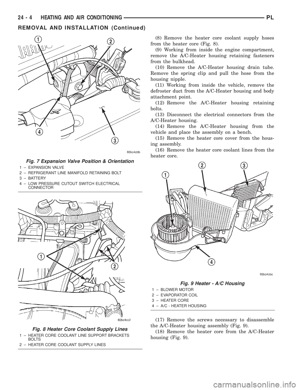
(8) Remove the heater core coolant supply hoses
from the heater core (Fig. 8).
(9) Working from inside the engine compartment,
remove the A/C-Heater housing retaining fasteners
from the bulkhead.
(10) Remove the A/C-Heater housing drain tube.
Remove the spring clip and pull the hose from the
housing nipple.
(11) Working from inside the vehicle, remove the
defroster duct from the A/C-Heater housing and body
attachment point.
(12) Remove the A/C-Heater housing retaining
bolts.
(13) Disconnect the electrical connectors from the
A/C-Heater housing.
(14) Remove the A/C-Heater housing from the
vehicle and place the assembly on a bench.
(15) Remove the heater core cover from the hous-
ing assembly.
(16) Remove the heater core coolant lines from the
heater core.
(17) Remove the screws necessary to disassemble
the A/C-Heater housing assembly (Fig. 9).
(18) Remove the heater core from the A/C-Heater
housing (Fig. 9).
Fig. 7 Expansion Valve Position & Orientation
1 ± EXPANSION VALVE
2 ± REFRIGERANT LINE MANIFOLD RETAINING BOLT
3 ± BATTERY
4 ± LOW PRESSURE CUTOUT SWITCH ELECTRICAL
CONNECTOR
Fig. 8 Heater Core Coolant Supply Lines
1 ± HEATER CORE COOLANT LINE SUPPORT BRACKETS
BOLTS
2 ± HEATER CORE COOLANT SUPPLY LINES
Fig. 9 Heater - A/C Housing
1 ± BLOWER MOTOR
2 ± EVAPORATOR COIL
3 ± HEATER CORE
4 ± A/C - HEATER HOUSING
24 - 4 HEATING AND AIR CONDITIONINGPL
REMOVAL AND INSTALLATION (Continued)
Page 1272 of 1285
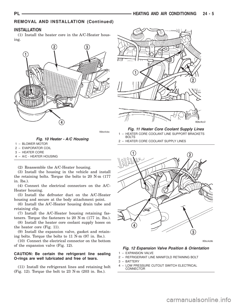
INSTALLATION
(1) Install the heater core in the A/C-Heater hous-
ing.
(2) Reassemble the A/C-Heater housing.
(3) Install the housing in the vehicle and install
the retaining bolts. Torque the bolts to 20 N´m (177
in. lbs.).
(4) Connect the electrical connectors on the A/C-
Heater housing.
(5) Install the defroster duct on the A/C-Heater
housing and secure at the body attachment point.
(6) Install the A/C-Heater housing drain tube and
retaining clip.
(7) Install the A/C-Heater housing retaining fas-
teners. Torque the fasteners to 20 N´m (177 in. lbs.).
(8) Install the heater core coolant supply hoses on
the heater core (Fig. 11).
(9) Install the expansion valve, gasket and retain-
ing bolts. Torque the bolts to 11 N´m (97 in. lbs.).
(10) Connect the electrical connector on the bottom
of the expansion valve (Fig. 12).
CAUTION: Be certain the refrigerant line sealing
O-rings are well lubricated and free of tears.
(11) Install the refrigerant lines and retaining bolt
(Fig. 12). Torque the bolt to 23 N´m (203 in. lbs.).
Fig. 10 Heater - A/C Housing
1 ± BLOWER MOTOR
2 ± EVAPORATOR COIL
3 ± HEATER CORE
4 ± A/C - HEATER HOUSING
Fig. 11 Heater Core Coolant Supply Lines
1 ± HEATER CORE COOLANT LINE SUPPORT BRACKETS
BOLTS
2 ± HEATER CORE COOLANT SUPPLY LINES
Fig. 12 Expansion Valve Position & Orientation
1 ± EXPANSION VALVE
2 ± REFRIGERANT LINE MANIFOLD RETAINING BOLT
3 ± BATTERY
4 ± LOW PRESSURE CUTOUT SWITCH ELECTRICAL
CONNECTOR
PLHEATING AND AIR CONDITIONING 24 - 5
REMOVAL AND INSTALLATION (Continued)
Page 1273 of 1285
(12) Install the instrument panel. Refer to Group
8E, Instrument Panel and Systems for the procedure.
(13) Charge the refrigerant system.
(14) Fill the cooling system. Refer to Group 7,
Cooling System for the procedure.
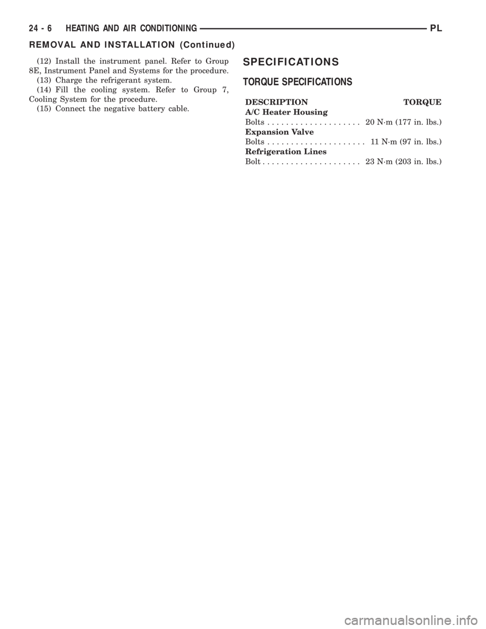
(15) Connect the negative battery cable.SPECIFICATIONS
TORQUE SPECIFICATIONS
DESCRIPTION TORQUE
A/C Heater Housing
Bolts.................... 20N´m(177 in. lbs.)
Expansion Valve
Bolts..................... 11N´m(97in.lbs.)
Refrigeration Lines
Bolt..................... 23N´m(203 in. lbs.)
24 - 6 HEATING AND AIR CONDITIONINGPL
REMOVAL AND INSTALLATION (Continued)
Page 1274 of 1285
INTRODUCTION
TABLE OF CONTENTS
page page
DESCRIPTION AND OPERATION
VEHICLE IDENTIFICATION NUMBER..........1
VEHICLE SAFETY CERTIFICATION LABEL......2
BODY CODE EMBOSS.....................2
SERVICE PROCEDURES
THREADED HOLE REPAIR..................2SPECIFICATIONS
INTERNATIONAL VEHICLE CONTROL AND
DISPLAY SYMBOLS.....................2
FASTENER IDENTIFICATION.................3
FASTENER USAGE........................6
METRIC SYSTEM.........................6
DESCRIPTION AND OPERATION
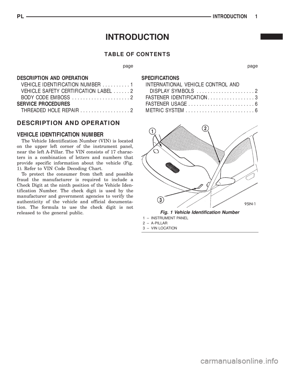
VEHICLE IDENTIFICATION NUMBER
The Vehicle Identification Number (VIN) is located
on the upper left corner of the instrument panel,
near the left A-Pillar. The VIN consists of 17 charac-
ters in a combination of letters and numbers that
provide specific information about the vehicle (Fig.
1). Refer to VIN Code Decoding Chart.
To protect the consumer from theft and possible
fraud the manufacturer is required to include a
Check Digit at the ninth position of the Vehicle Iden-
tification Number. The check digit is used by the
manufacturer and government agencies to verify the
authenticity of the vehicle and official documenta-
tion. The formula to use the check digit is not
released to the general public.
Fig. 1 Vehicle Identification Number
1 ± INSTRUMENT PANEL
2 ± A-PILLAR
3 ± VIN LOCATION
PLINTRODUCTION 1
Page 1275 of 1285
VIN CODE DECODING
POSITION INTERPRETATION CODE = DESCRIPTION
1 Country of Origin 1 = United states
2 MakeB = Dodge
P = Plymouth
3 Vehicle Type 3 = Passenger Car
4 Pass. Safety E = Restraint System, Active Driver & Passenger Airbags
5 Car Line S = Neon
6 Series2 = Low Line
4 = High Line
7 Body Style6 = 4 Door Sedan
8 Engine C = 2.0 L 4 Cyl. 16V
9 Check Digit See explanation in this section.
10 Model Year Y = 2000
11 Assembly Plant D = Belvidere
12 Thru 17 Vehicle Build Sequence 6 digit number assigned by assembly plant.
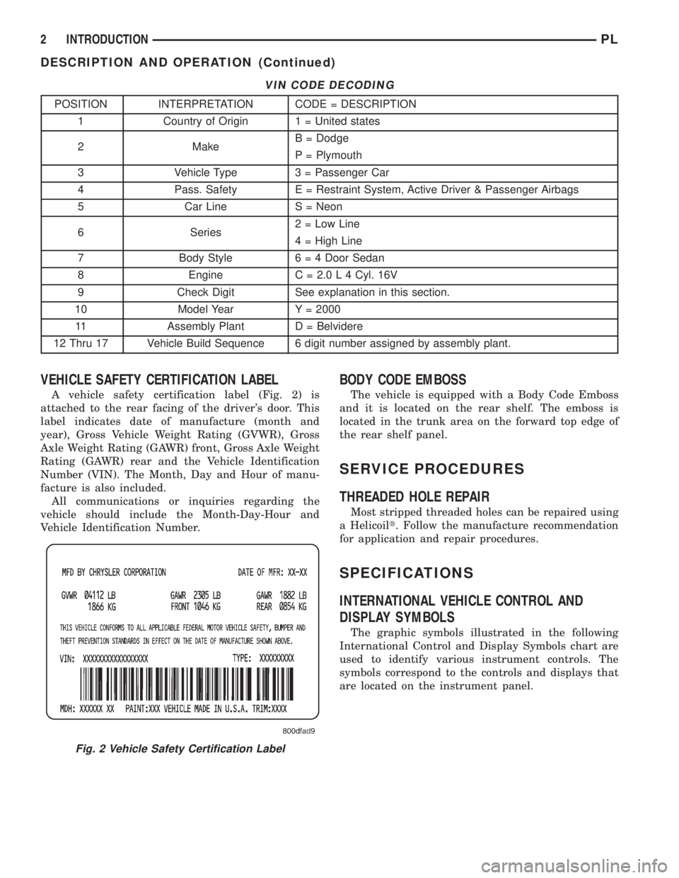
VEHICLE SAFETY CERTIFICATION LABEL
A vehicle safety certification label (Fig. 2) is
attached to the rear facing of the driver's door. This
label indicates date of manufacture (month and
year), Gross Vehicle Weight Rating (GVWR), Gross
Axle Weight Rating (GAWR) front, Gross Axle Weight
Rating (GAWR) rear and the Vehicle Identification
Number (VIN). The Month, Day and Hour of manu-
facture is also included.
All communications or inquiries regarding the
vehicle should include the Month-Day-Hour and
Vehicle Identification Number.
BODY CODE EMBOSS
The vehicle is equipped with a Body Code Emboss
and it is located on the rear shelf. The emboss is
located in the trunk area on the forward top edge of
the rear shelf panel.
SERVICE PROCEDURES
THREADED HOLE REPAIR
Most stripped threaded holes can be repaired using
a Helicoilt. Follow the manufacture recommendation
for application and repair procedures.
SPECIFICATIONS
INTERNATIONAL VEHICLE CONTROL AND
DISPLAY SYMBOLS
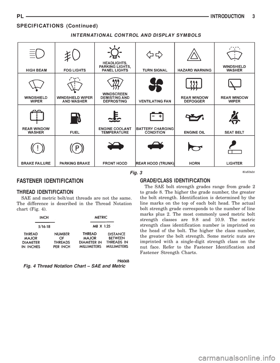
The graphic symbols illustrated in the following
International Control and Display Symbols chart are
used to identify various instrument controls. The
symbols correspond to the controls and displays that
are located on the instrument panel.
Fig. 2 Vehicle Safety Certification Label
2 INTRODUCTIONPL
DESCRIPTION AND OPERATION (Continued)
Page 1276 of 1285
FASTENER IDENTIFICATION
THREAD IDENTIFICATION
SAE and metric bolt/nut threads are not the same.
The difference is described in the Thread Notation
chart (Fig. 4).
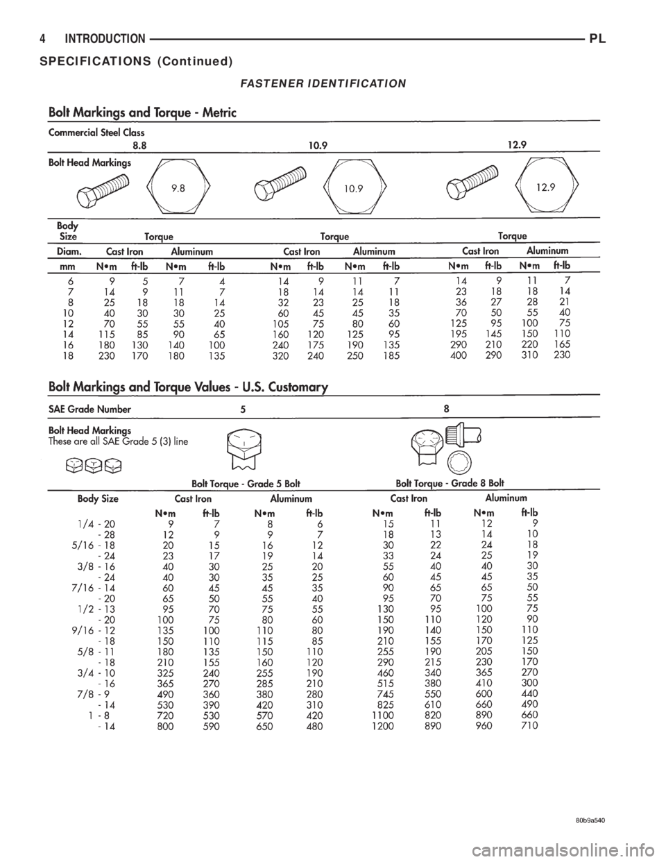
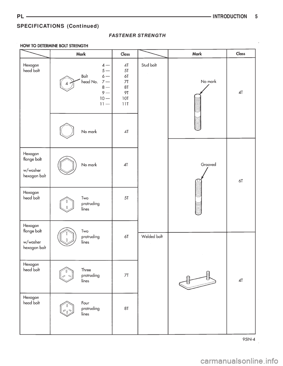
GRADE/CLASS IDENTIFICATION
The SAE bolt strength grades range from grade 2
to grade 8. The higher the grade number, the greater
the bolt strength. Identification is determined by the
line marks on the top of each bolt head. The actual
bolt strength grade corresponds to the number of line
marks plus 2. The most commonly used metric bolt
strength classes are 9.8 and 10.9. The metric
strength class identification number is imprinted on
the head of the bolt. The higher the class number,
the greater the bolt strength. Some metric nuts are
imprinted with a single-digit strength class on the
nut face. Refer to the Fastener Identification and
Fastener Strength Charts.
INTERNATIONAL CONTROL AND DISPLAY SYMBOLS
Fig. 3
Fig. 4 Thread Notation Chart ± SAE and Metric
PLINTRODUCTION 3
SPECIFICATIONS (Continued)
Page 1277 of 1285
FASTENER IDENTIFICATION
4 INTRODUCTIONPL
SPECIFICATIONS (Continued)
Page 1278 of 1285
FASTENER STRENGTH
PLINTRODUCTION 5
SPECIFICATIONS (Continued)
Page 1279 of 1285
FASTENER USAGE
WARNING: USE OF AN INCORRECT FASTENER
MAY RESULT IN COMPONENT DAMAGE OR PER-
SONAL INJURY.
Figure art, specifications and tightening torque ref-
erences in this manual are identified in metric and
SAE format.
During any maintenance or repair procedures, it is
important to salvage all fasteners (nuts, bolts, etc.)
for reassembly. If the fastener is not salvageable, a
fastener of equivalent specification must be use.
METRIC SYSTEM
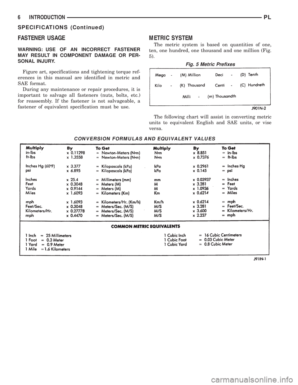
The metric system is based on quantities of one,
ten, one hundred, one thousand and one million (Fig.
5).
The following chart will assist in converting metric
units to equivalent English and SAE units, or vise
versa.
CONVERSION FORMULAS AND EQUIVALENT VALUES
Fig. 5 Metric Prefixes
6 INTRODUCTIONPL
SPECIFICATIONS (Continued)
Page 1280 of 1285
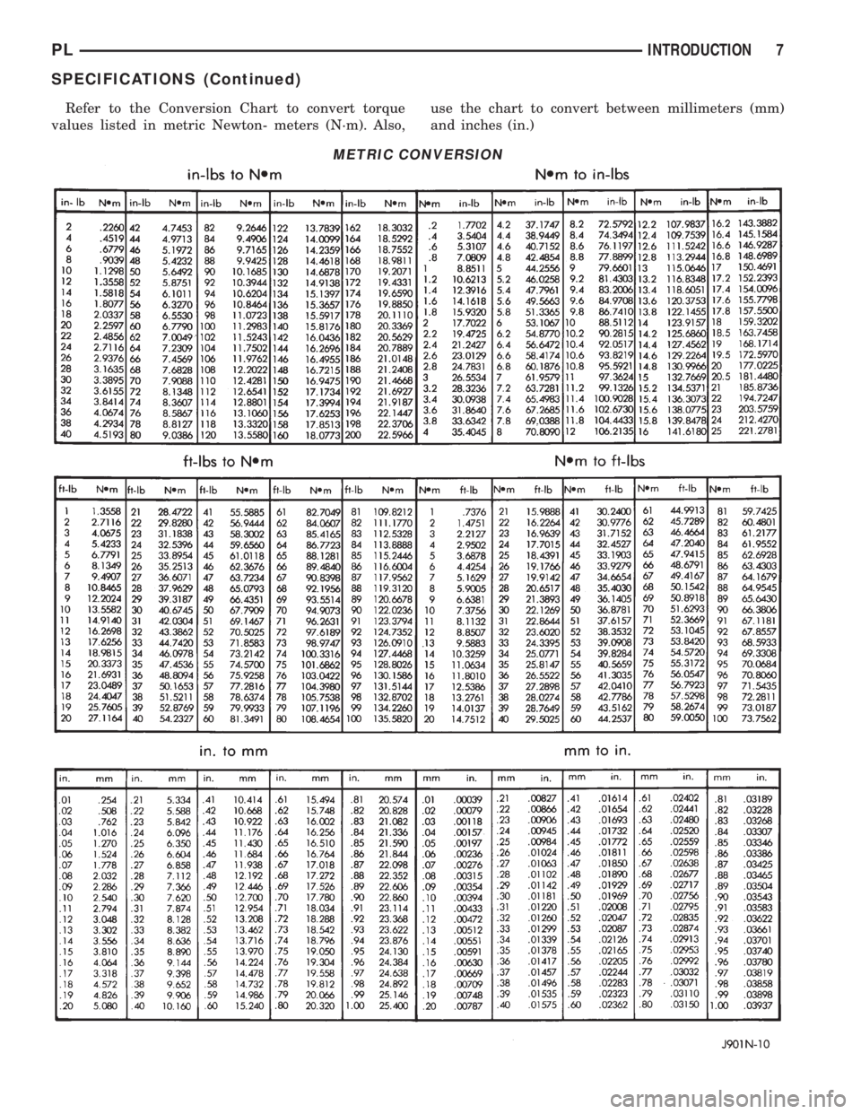
Refer to the Conversion Chart to convert torque
values listed in metric Newton- meters (N´m). Also,use the chart to convert between millimeters (mm)
and inches (in.)
METRIC CONVERSION
PLINTRODUCTION 7
SPECIFICATIONS (Continued)