DODGE NEON 2000 Service Repair Manual
Manufacturer: DODGE, Model Year: 2000, Model line: NEON, Model: DODGE NEON 2000Pages: 1285, PDF Size: 29.42 MB
Page 171 of 1285
the ignition key to the start position. The engine
starter should crank. If the starter does not crank,
visually inspect the clutch pedal for obstructions
(floor mat, etc.). Also make sure the clutch pedal
blade contacts and fully
Electrical Test
(1) Move ignition key to the ªOFF/LOCKº position
and remove key.
(2) Set park brake.
(3) Disconnect the clutch interlock/upstop switch
connector.
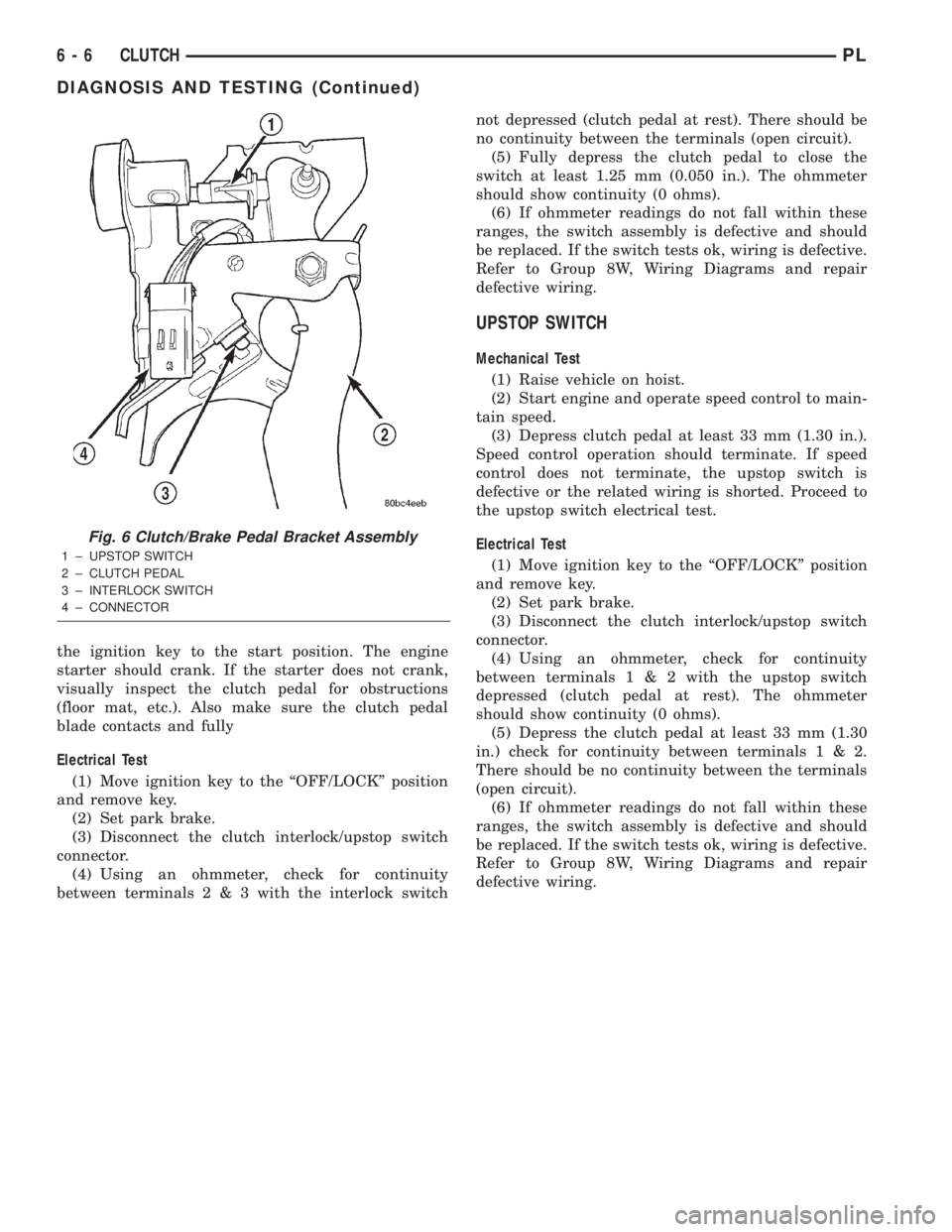
(4) Using an ohmmeter, check for continuity
between terminals2&3with the interlock switchnot depressed (clutch pedal at rest). There should be
no continuity between the terminals (open circuit).
(5) Fully depress the clutch pedal to close the
switch at least 1.25 mm (0.050 in.). The ohmmeter
should show continuity (0 ohms).
(6) If ohmmeter readings do not fall within these
ranges, the switch assembly is defective and should
be replaced. If the switch tests ok, wiring is defective.
Refer to Group 8W, Wiring Diagrams and repair
defective wiring.
UPSTOP SWITCH
Mechanical Test
(1) Raise vehicle on hoist.
(2) Start engine and operate speed control to main-
tain speed.
(3) Depress clutch pedal at least 33 mm (1.30 in.).
Speed control operation should terminate. If speed
control does not terminate, the upstop switch is
defective or the related wiring is shorted. Proceed to
the upstop switch electrical test.
Electrical Test
(1) Move ignition key to the ªOFF/LOCKº position
and remove key.
(2) Set park brake.
(3) Disconnect the clutch interlock/upstop switch
connector.
(4) Using an ohmmeter, check for continuity
between terminals1&2with the upstop switch
depressed (clutch pedal at rest). The ohmmeter
should show continuity (0 ohms).
(5) Depress the clutch pedal at least 33 mm (1.30
in.) check for continuity between terminals1&2.
There should be no continuity between the terminals
(open circuit).
(6) If ohmmeter readings do not fall within these
ranges, the switch assembly is defective and should
be replaced. If the switch tests ok, wiring is defective.
Refer to Group 8W, Wiring Diagrams and repair
defective wiring.
Fig. 6 Clutch/Brake Pedal Bracket Assembly
1 ± UPSTOP SWITCH
2 ± CLUTCH PEDAL
3 ± INTERLOCK SWITCH
4 ± CONNECTOR
6 - 6 CLUTCHPL
DIAGNOSIS AND TESTING (Continued)
Page 172 of 1285
SERVICE DIAGNOSIS±CLUTCH INTERLOCK/UPSTOP SWITCH
CONDITION POSSIBLE CAUSES CORRECTION
ENGINE STARTER
WON'T CRANK
WHEN CLUTCH
PEDAL IS
PRESSED TO THE
FLOORClutch interlock switch does not have
continuity when plunger is depressed 1.25
mm (1.30 in.)Defective switch or open wiring circuit.
Replace switch if necessary.
Interlock switch plunger is not depressed
when clutch pedal is pushed to the floorFloor mat interferes with clutch pedal
movement or clutch pedal bracket is bent.
Problem is related to other components in
the starting circuit.Check other components in the starting
circuit. Refer to Battery/Starting/Charging
System in Group 8.
SPEED CONTROL
DOES NOT
TERMINATE WHEN
CLUTCH PEDAL IS
DEPRESSED BY AT
LEAST 33 mm (1.30
in.)Upstop switch circuit is closed when clutch
pedal is depressed, or harness is shorted.Refer to Upstop Switch Electrical Test in
this group. Repair wiring or replace switch
assembly as necessary.
Other speed control system failure. Refer to Group 8H, Speed Control for
further diagnosis and testing procedures.
REMOVAL AND INSTALLATION
CLUTCH CABLE
REMOVAL
(1) Disconnect both battery cables.
(2) Remove battery clamp and remove battery
from vehicle.
(3) Remove battery tray from mount bracket.
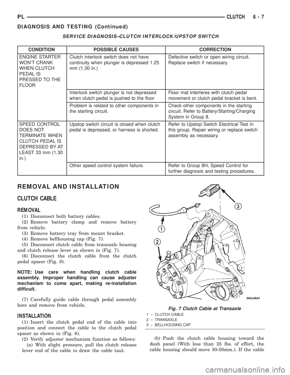
(4) Remove bellhousing cap (Fig. 7).
(5) Disconnect clutch cable from transaxle housing
and clutch release lever as shown in (Fig. 7).
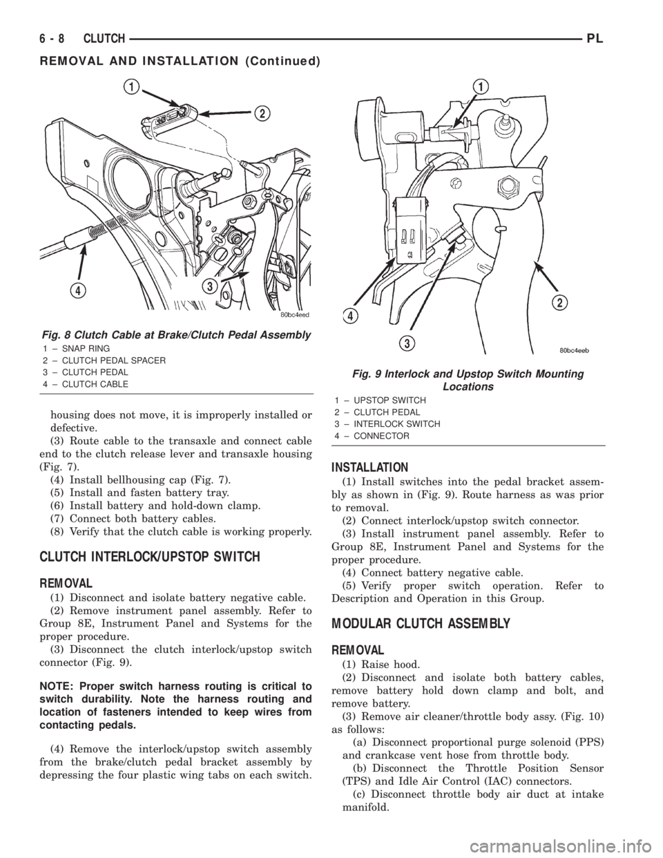
(6) Disconnect the clutch cable from the clutch
pedal spacer (Fig. 8).
NOTE: Use care when handling clutch cable
assembly. Improper handling can cause adjuster
mechanism to come apart, making re-installation
difficult.
(7) Carefully guide cable through pedal assembly
bore and remove from vehicle.
INSTALLATION
(1) Insert the clutch pedal end of the cable into
position and connect the cable to the clutch pedal
spacer as shown in (Fig. 8).
(2) Verify adjuster mechanism function as follows:
(a) With slight pressure, pull the clutch release
lever end of the cable to draw the cable taut.(b) Push the clutch cable housing toward the
dash panel (With less than 25 lbs. of effort, the
cable housing should move 30-50mm.). If the cable
Fig. 7 Clutch Cable at Transaxle
1 ± CLUTCH CABLE
2 ± TRANSAXLE
3 ± BELLHOUSING CAP
PLCLUTCH 6 - 7
DIAGNOSIS AND TESTING (Continued)
Page 173 of 1285
housing does not move, it is improperly installed or
defective.
(3) Route cable to the transaxle and connect cable
end to the clutch release lever and transaxle housing
(Fig. 7).
(4) Install bellhousing cap (Fig. 7).
(5) Install and fasten battery tray.
(6) Install battery and hold-down clamp.
(7) Connect both battery cables.
(8) Verify that the clutch cable is working properly.
CLUTCH INTERLOCK/UPSTOP SWITCH
REMOVAL
(1) Disconnect and isolate battery negative cable.
(2) Remove instrument panel assembly. Refer to
Group 8E, Instrument Panel and Systems for the
proper procedure.
(3) Disconnect the clutch interlock/upstop switch
connector (Fig. 9).
NOTE: Proper switch harness routing is critical to
switch durability. Note the harness routing and
location of fasteners intended to keep wires from
contacting pedals.
(4) Remove the interlock/upstop switch assembly
from the brake/clutch pedal bracket assembly by
depressing the four plastic wing tabs on each switch.
INSTALLATION
(1) Install switches into the pedal bracket assem-
bly as shown in (Fig. 9). Route harness as was prior
to removal.
(2) Connect interlock/upstop switch connector.
(3) Install instrument panel assembly. Refer to
Group 8E, Instrument Panel and Systems for the
proper procedure.
(4) Connect battery negative cable.
(5) Verify proper switch operation. Refer to
Description and Operation in this Group.
MODULAR CLUTCH ASSEMBLY
REMOVAL
(1) Raise hood.
(2) Disconnect and isolate both battery cables,
remove battery hold down clamp and bolt, and
remove battery.
(3) Remove air cleaner/throttle body assy. (Fig. 10)
as follows:
(a) Disconnect proportional purge solenoid (PPS)
and crankcase vent hose from throttle body.
(b) Disconnect the Throttle Position Sensor
(TPS) and Idle Air Control (IAC) connectors.
(c) Disconnect throttle body air duct at intake
manifold.
Fig. 8 Clutch Cable at Brake/Clutch Pedal Assembly
1 ± SNAP RING
2 ± CLUTCH PEDAL SPACER
3 ± CLUTCH PEDAL
4 ± CLUTCH CABLE
Fig. 9 Interlock and Upstop Switch Mounting
Locations
1 ± UPSTOP SWITCH
2 ± CLUTCH PEDAL
3 ± INTERLOCK SWITCH
4 ± CONNECTOR
6 - 8 CLUTCHPL
REMOVAL AND INSTALLATION (Continued)
Page 174 of 1285
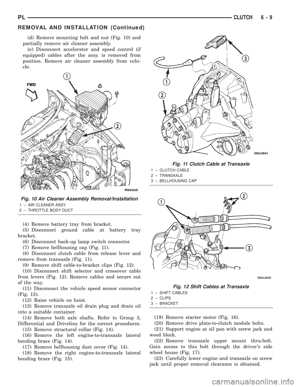
(d) Remove mounting bolt and nut (Fig. 10) and
partially remove air cleaner assembly.
(e) Disconnect accelerator and speed control (if
equipped) cables after the assy. is removed from
position. Remove air cleaner assembly from vehi-
cle.
(4) Remove battery tray from bracket.
(5) Disconnect ground cable at battery tray
bracket.
(6) Disconnect back-up lamp switch connector.
(7) Remove bellhousing cap (Fig. 11).
(8) Disconnect clutch cable from release lever and
remove from transaxle (Fig. 11).
(9) Remove shift cable-to-bracket clips (Fig. 12).
(10) Disconnect shift selector and crossover cable
from levers (Fig. 12). Remove cables and secure out
of the way.
(11) Disconnect the vehicle speed sensor connector
(Fig. 13).
(12) Raise vehicle on hoist.
(13) Remove transaxle oil drain plug and drain oil
into a suitable container.
(14) Remove both axle shafts. Refer to Group 3,
Differential and Driveline for the correct procedures.
(15) Remove structural collar (Fig. 14).
(16) Remove the left engine-to-transaxle lateral
bending brace (Fig. 14).
(17) Remove bellhousing dust cover (Fig. 14).
(18) Remove the right engine-to-transaxle lateral
bending brace (Fig. 15).(19) Remove starter motor (Fig. 16).
(20) Remove drive plate-to-clutch module bolts.
(21) Support engine at oil pan with screw jack and
wood block.
(22) Remove transaxle upper mount thru-bolt.
Gain access to this bolt through the driver's side
wheel house (Fig. 17).
(23) Carefully lower engine and transaxle on screw
jack until proper removal clearance is obtained.
Fig. 10 Air Cleaner Assembly Removal/Installation
1 ± AIR CLEANER ASSY.
2 ± THROTTLE BODY DUCTFWD
Fig. 11 Clutch Cable at Transaxle
1 ± CLUTCH CABLE
2 ± TRANSAXLE
3 ± BELLHOUSING CAP
Fig. 12 Shift Cables at Transaxle
1 ± SHIFT CABLES
2 ± CLIPS
3 ± BRACKET
PLCLUTCH 6 - 9
REMOVAL AND INSTALLATION (Continued)
Page 175 of 1285
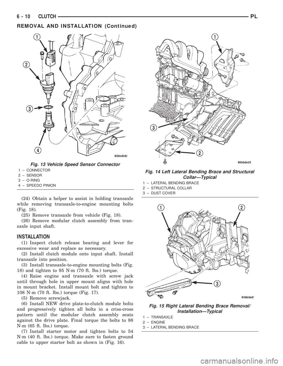
(24) Obtain a helper to assist in holding transaxle
while removing transaxle-to-engine mounting bolts
(Fig. 18).
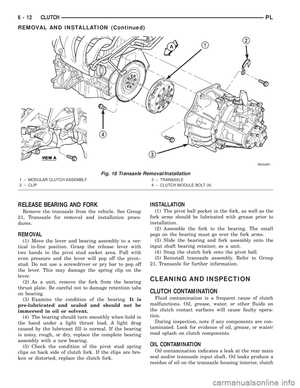
(25) Remove transaxle from vehicle (Fig. 18).
(26) Remove modular clutch assembly from tran-
saxle input shaft.
INSTALLATION
(1) Inspect clutch release bearing and lever for
excessive wear and replace as necessary.
(2) Install clutch module onto input shaft. Install
transaxle into position.
(3) Install transaxle-to-engine mounting bolts (Fig.
18) and tighten to 95 N´m (70 ft. lbs.) torque.
(4) Raise engine and transaxle with screw jack
until through hole in upper mount aligns with hole
in mount bracket. Install mount bolt and tighten to
108 N´m (70 ft. lbs.) torque (Fig. 17).
(5) Remove screwjack.
(6) Install NEW drive plate-to-clutch module bolts
and progressively tighten all bolts in a criss-cross
pattern until the modular clutch assembly seats
against the drive plate. Final torque the bolts to 88
N´m (65 ft. lbs.) torque.
(7) Install starter motor and tighten bolts to 54
N´m (40 ft. lbs.) torque. Make sure to fasten ground
cable to upper starter bolt as shown in (Fig. 16).
Fig. 13 Vehicle Speed Sensor Connector
1 ± CONNECTOR
2 ± SENSOR
3 ± O-RING
4 ± SPEEDO PINIONFig. 14 Left Lateral Bending Brace and Structural
CollarÐTypical
1 ± LATERAL BENDING BRACE
2 ± STRUCTURAL COLLAR
3 ± DUST COVER
Fig. 15 Right Lateral Bending Brace Removal/
InstallationÐTypical
1 ± TRANSAXLE
2 ± ENGINE
3 ± LATERAL BENDING BRACE
6 - 10 CLUTCHPL
REMOVAL AND INSTALLATION (Continued)
Page 176 of 1285
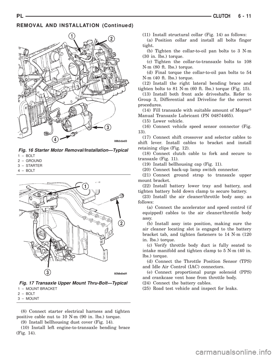
(8) Connect starter electrical harness and tighten
positive cable nut to 10 N´m (90 in. lbs.) torque.
(9) Install bellhousing dust cover (Fig. 14).
(10) Install left engine-to-transaxle bending brace
(Fig. 14).(11) Install structural collar (Fig. 14) as follows:
(a) Position collar and install all bolts finger
tight.
(b) Tighten the collar-to-oil pan bolts to 3 N´m
(30 in. lbs.) torque.
(c) Tighten the collar-to-transaxle bolts to 108
N´m (80 ft. lbs.) torque.
(d) Final torque the collar-to-oil pan bolts to 54
N´m (40 ft. lbs.) torque.
(12) Install the right lateral bending brace and
tighten bolts to 81 N´m (60 ft. lbs.) torque (Fig. 15).
(13) Install both front axle driveshafts. Refer to
Group 3, Differential and Driveline for the correct
procedures.
(14) Fill transaxle with suitable amount of Mopart
Manual Transaxle Lubricant (PN 04874465).
(15) Lower vehicle.
(16) Connect vehicle speed sensor connector (Fig.
13).
(17) Connect shift crossover and selector cables to
shift lever. Install cables to bracket and install
retaining clips (Fig. 12).
(18) Connect clutch cable to fork and secure to
transaxle (Fig. 11).
(19) Install bellhousing cap (Fig. 11).
(20) Connect back-up lamp switch connector.
(21) Connect ground strap to transaxle upper
mount bracket.
(22) Install battery lower tray and battery, and
tighten battery hold down clamp to secure battery.
(23) Install the air cleaner/throttle body assy. as
follows:
(a) Connect the accelerator and speed control (if
equipped) cables to the air cleaner/throttle body
assy.
(b) Install assy into position, making sure the
air cleaner locating slot is engaged to the battery
bracket tab, and tighten fasteners to 14 N´m (120
in. lbs.) torque.
(c) Verify throttle body duct is fully seated to
intake manifold and tighten clamp to 5 N´m (40 in.
lbs.) torque.
(d) Connect the Throttle Position Sensor (TPS)
and Idle Air Control (IAC) connectors.
(e) Connect proportional purge solenoid (PPS)
and crankcase vent hose from throttle body.
(24) Connect the battery cables.
(25) Road test vehicle and inspect for leaks.
Fig. 16 Starter Motor Removal/InstallationÐTypical
1 ± BOLT
2 ± GROUND
3±STARTER
4 ± BOLT
Fig. 17 Transaxle Upper Mount Thru-BoltÐTypical
1 ± MOUNT BRACKET
2 ± BOLT
3 ± MOUNT
PLCLUTCH 6 - 11
REMOVAL AND INSTALLATION (Continued)
Page 177 of 1285
RELEASE BEARING AND FORK
Remove the transaxle from the vehicle. See Group
21, Transaxle for removal and installation proce-
dures.
REMOVAL
(1) Move the lever and bearing assembly to a ver-
tical in-line position. Grasp the release lever with
two hands in the pivot stud socket area. Pull with
even pressure and the lever will pop off the pivot±
stud. Do not use a screwdriver or pry bar to pop off
the lever. This may damage the spring clip on the
lever.
(2) As a unit, remove the fork from the bearing
thrust plate. Be careful not to damage retention tabs
on bearing.
(3) Examine the condition of the bearing.It is
pre-lubricated and sealed and should not be
immersed in oil or solvent.
(4) The bearing should turn smoothly when held in
the hand under a light thrust load. A light drag
caused by the lubricant fill is normal. If the bearing
is noisy, rough, or dry, replace the complete bearing
assembly with a new bearing.
(5) Check the condition of the pivot stud spring
clips on back side of clutch fork. If the clips are bro-
ken or distorted, replace the clutch fork.
INSTALLATION
(1) The pivot ball pocket in the fork, as well as the
fork arms should be lubricated with grease prior to
installation.
(2) Assemble the fork to the bearing. The small
pegs on the bearing must go over the fork arms.
(3) Slide the bearing and fork assembly onto the
input shaft bearing retainer, as a unit.
(4) Snap the clutch fork onto the pivot ball.
(5) Reinstall transaxle assembly. Refer to Group
21, Transaxle for further information.
CLEANING AND INSPECTION
CLUTCH CONTAMINATION
Fluid contamination is a frequent cause of clutch
malfunctions. Oil, grease, water, or other fluids on
the clutch contact surfaces will cause faulty opera-
tion.
During inspection, note if any components are con-
taminated. Look for evidence of oil, grease, or water/
road splash on clutch components.
OIL CONTAMINATION
Oil contamination indicates a leak at the rear main
seal and/or transaxle input shaft. Oil leaks produce a
residue of oil on the transaxle housing interior, clutch
Fig. 18 Transaxle Removal/Installation
1 ± MODULAR CLUTCH ASSEMBLY
2 ± CLIP3 ± TRANSAXLE
4 ± CLUTCH MODULE BOLT (4)
VIEW A
6 - 12 CLUTCHPL
REMOVAL AND INSTALLATION (Continued)
Page 178 of 1285
cover and flywheel. Heat buildup caused by slippage
can bake the oil residue onto the components. This
glaze-like residue ranges in color from amber to
black.
GREASE CONTAMINATION
Grease contamination is usually a product of over-
lubrication. During clutch service, apply only a small
amount of grease to the input shaft splines. Excess
grease may be thrown off during operation, contami-
nating the disc.
ROAD SPLASH/WATER CONTAMINATION
Road splash contamination is usually caused by
driving the vehicle through deep water puddles.
Water can be forced into the clutch housing, causing
clutch components to become contaminated. Facing of
disc will absorb moisture and bond to the flywheel
and/or, pressure plate, if vehicle is allowed to stand
for some time before use. If this condition occurs,
replacement of clutch assembly may be required.
Drive the vehicle until normal clutch operating tem-
perature has been obtained. This will dry off disc
assembly, pressure plate, and flywheel.
CLEANING PRECAUTIONS
Condensation from steam vapors tend to accumu-
late on the internal clutch mechanism when the vehi-
cle is steam cleaned. Facing of disc will absorb
moisture and will bond to flywheel and/or pressure
plate, if vehicle is allowed to stand for some time
before use. If this condition occurs, it may require
replacement of clutch assembly. After cleaning, drive
the vehicle to its normal clutch operating tempera-
ture. This will dry off disc assembly, pressure plate,
and flywheel.
SPECIFICATIONS
TORQUE
DESCRIPTION TORQUE
Modular Clutch-to-Drive Plate Bolts..... 88N´m
(65 ft. lbs.)
Transaxle-to-Engine Mounting Bolts...... 95N´m
(70 ft. lbs.)
PLCLUTCH 6 - 13
CLEANING AND INSPECTION (Continued)
Page 179 of 1285

Page 180 of 1285
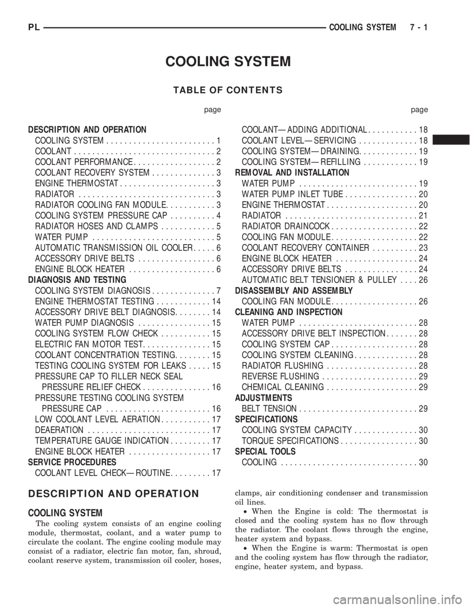
COOLING SYSTEM
TABLE OF CONTENTS
page page
DESCRIPTION AND OPERATION
COOLING SYSTEM........................1
COOLANT...............................2
COOLANT PERFORMANCE..................2
COOLANT RECOVERY SYSTEM..............3
ENGINE THERMOSTAT.....................3
RADIATOR..............................3
RADIATOR COOLING FAN MODULE...........3
COOLING SYSTEM PRESSURE CAP..........4
RADIATOR HOSES AND CLAMPS............5
WATER PUMP...........................5
AUTOMATIC TRANSMISSION OIL COOLER.....6
ACCESSORY DRIVE BELTS.................6
ENGINE BLOCK HEATER...................6
DIAGNOSIS AND TESTING
COOLING SYSTEM DIAGNOSIS..............7
ENGINE THERMOSTAT TESTING............14
ACCESSORY DRIVE BELT DIAGNOSIS........14
WATER PUMP DIAGNOSIS................15
COOLING SYSTEM FLOW CHECK...........15
ELECTRIC FAN MOTOR TEST...............15
COOLANT CONCENTRATION TESTING........15
TESTING COOLING SYSTEM FOR LEAKS.....15
PRESSURE CAP TO FILLER NECK SEAL
PRESSURE RELIEF CHECK...............16
PRESSURE TESTING COOLING SYSTEM
PRESSURE CAP.......................16
LOW COOLANT LEVEL AERATION...........17
DEAERATION...........................17
TEMPERATURE GAUGE INDICATION.........17
ENGINE BLOCK HEATER..................17
SERVICE PROCEDURES
COOLANT LEVEL CHECKÐROUTINE.........17COOLANTÐADDING ADDITIONAL...........18
COOLANT LEVELÐSERVICING.............18
COOLING SYSTEMÐDRAINING.............19
COOLING SYSTEMÐREFILLING............19
REMOVAL AND INSTALLATION
WATER PUMP..........................19
WATER PUMP INLET TUBE................20
ENGINE THERMOSTAT....................20
RADIATOR.............................21
RADIATOR DRAINCOCK...................22
COOLING FAN MODULE...................22
COOLANT RECOVERY CONTAINER..........23
ENGINE BLOCK HEATER..................24
ACCESSORY DRIVE BELTS................24
AUTOMATIC BELT TENSIONER & PULLEY....26
DISASSEMBLY AND ASSEMBLY
COOLING FAN MODULE...................26
CLEANING AND INSPECTION
WATER PUMP..........................28
ACCESSORY DRIVE BELT INSPECTION.......28
COOLING SYSTEM CAP...................28
COOLING SYSTEM CLEANING..............28
RADIATOR FLUSHING....................28
REVERSE FLUSHING.....................29
CHEMICAL CLEANING....................29
ADJUSTMENTS
BELT TENSION..........................29
SPECIFICATIONS
COOLING SYSTEM CAPACITY..............30
TORQUE SPECIFICATIONS.................30
SPECIAL TOOLS
COOLING..............................30
DESCRIPTION AND OPERATION
COOLING SYSTEM
The cooling system consists of an engine cooling
module, thermostat, coolant, and a water pump to
circulate the coolant. The engine cooling module may
consist of a radiator, electric fan motor, fan, shroud,
coolant reserve system, transmission oil cooler, hoses,clamps, air conditioning condenser and transmission
oil lines.
²When the Engine is cold: The thermostat is
closed and the cooling system has no flow through
the radiator. The coolant flows through the engine,
heater system and bypass.
²When the Engine is warm: Thermostat is open
and the cooling system has flow through the radiator,
engine, heater system, and bypass.
PLCOOLING SYSTEM 7 - 1