wheel bolts DODGE NEON 2000 Service Service Manual
[x] Cancel search | Manufacturer: DODGE, Model Year: 2000, Model line: NEON, Model: DODGE NEON 2000Pages: 1285, PDF Size: 29.42 MB
Page 142 of 1285
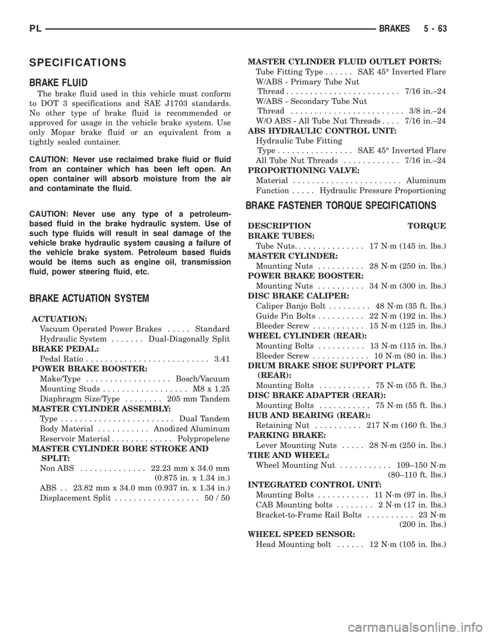
SPECIFICATIONS
BRAKE FLUID
The brake fluid used in this vehicle must conform
to DOT 3 specifications and SAE J1703 standards.
No other type of brake fluid is recommended or
approved for usage in the vehicle brake system. Use
only Mopar brake fluid or an equivalent from a
tightly sealed container.
CAUTION: Never use reclaimed brake fluid or fluid
from an container which has been left open. An
open container will absorb moisture from the air
and contaminate the fluid.
CAUTION: Never use any type of a petroleum-
based fluid in the brake hydraulic system. Use of
such type fluids will result in seal damage of the
vehicle brake hydraulic system causing a failure of
the vehicle brake system. Petroleum based fluids
would be items such as engine oil, transmission
fluid, power steering fluid, etc.
BRAKE ACTUATION SYSTEM
ACTUATION:
Vacuum Operated Power Brakes.....Standard
Hydraulic System.......Dual-Diagonally Split
BRAKE PEDAL:
Pedal Ratio..........................3.41
POWER BRAKE BOOSTER:
Make/Type..................Bosch/Vacuum
Mounting Studs.................. M8x1.25
Diaphragm Size/Type........ 205mmTandem
MASTER CYLINDER ASSEMBLY:
Type ........................Dual Tandem
Body Material...........Anodized Aluminum
Reservoir Material.............Polypropelene
MASTER CYLINDER BORE STROKE AND
SPLIT:
NonABS ..............22.23 mm x 34.0 mm
(0.875 in. x 1.34 in.)
ABS . . 23.82 mm x 34.0 mm (0.937 in. x 1.34 in.)
Displacement Split.................. 50/50MASTER CYLINDER FLUID OUTLET PORTS:
Tube Fitting Type...... SAE45ÉInverted Flare
W/ABS - Primary Tube Nut
Thread........................7/16 in.±24
W/ABS - Secondary Tube Nut
Thread........................ 3/8in.±24
W/O ABS - All Tube Nut Threads....7/16 in.±24
ABS HYDRAULIC CONTROL UNIT:
Hydraulic Tube Fitting
Type................ SAE45ÉInverted Flare
All Tube Nut Threads............7/16 in.±24
PROPORTIONING VALVE:
Material.......................Aluminum
Function.....Hydraulic Pressure Proportioning
BRAKE FASTENER TORQUE SPECIFICATIONS
DESCRIPTION TORQUE
BRAKE TUBES:
Tube Nuts............... 17N´m(145 in. lbs.)
MASTER CYLINDER:
Mounting Nuts.......... 28N´m(250 in. lbs.)
POWER BRAKE BOOSTER:
Mounting Nuts.......... 34N´m(300 in. lbs.)
DISC BRAKE CALIPER:
Caliper Banjo Bolt......... 48N´m(35ft.lbs.)
Guide Pin Bolts.......... 22N´m(192 in. lbs.)
Bleeder Screw........... 15N´m(125 in. lbs.)
WHEEL CYLINDER (REAR):
Mounting Bolts.......... 13N´m(115in.lbs.)
Bleeder Screw............ 10N´m(80in.lbs.)
DRUM BRAKE SHOE SUPPORT PLATE
(REAR):
Mounting Bolts........... 75N´m(55ft.lbs.)
DISC BRAKE ADAPTER (REAR):
Mounting Bolts........... 75N´m(55ft.lbs.)
HUB AND BEARING (REAR):
Retaining Nut.......... 217N´m(160 ft. lbs.)
PARKING BRAKE:
Lever Mounting Nuts..... 28N´m(250 in. lbs.)
TIRE AND WHEEL:
Wheel Mounting Nut...........109±150 N´m
(80±110 ft. lbs.)
INTEGRATED CONTROL UNIT:
Mounting Bolts........... 11N´m(97in.lbs.)
CAB Mounting bolts........ 2N´m(17in.lbs.)
Bracket-to-Frame Rail Bolts.......... 23N´m
(200 in. lbs.)
WHEEL SPEED SENSOR:
Head Mounting bolt...... 12N´m(105 in. lbs.)
PLBRAKES 5 - 63
Page 145 of 1285
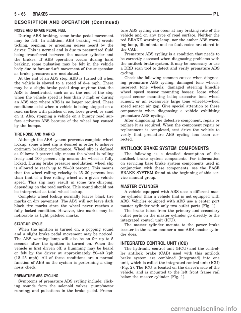
NOISE AND BRAKE PEDAL FEEL
During ABS braking, some brake pedal movement
may be felt. In addition, ABS braking will create
ticking, popping, or groaning noises heard by the
driver. This is normal and is due to pressurized fluid
being transferred between the master cylinder and
the brakes. If ABS operation occurs during hard
braking, some pulsation may be felt in the vehicle
body due to fore-and-aft movement of the suspension
as brake pressures are modulated.
At the end of an ABS stop, ABS is turned off when
the vehicle is slowed to a speed of 3±4 mph. There
may be a slight brake pedal drop anytime that the
ABS is deactivated, such as at the end of the stop
when the vehicle speed is less than 3 mph or during
an ABS stop where ABS is no longer required. These
conditions exist when a vehicle is being stopped on a
road surface with patches of ice, loose gravel, or sand
on it. Also, stopping a vehicle on a bumpy road sur-
face activates ABS because of the wheel hop caused
by the bumps.
TIRE NOISE AND MARKS
Although the ABS system prevents complete wheel
lockup, some wheel slip is desired in order to achieve
optimum braking performance. Wheel slip is defined
as follows: 0 percent slip means the wheel is rolling
freely and 100 percent slip means the wheel is fully
locked. During brake pressure modulation, wheel slip
is allowed to reach up to 25±30 percent. This means
that the wheel rolling velocity is 25±30 percent less
than that of a free rolling wheel at a given vehicle
speed. This slip may result in some tire chirping,
depending on the road surface. This sound should not
be interpreted as total wheel lockup.
Complete wheel lockup normally leaves black tire
marks on dry pavement. The ABS will not leave dark
black tire marks since the wheel never reaches a
fully locked condition. However, tire marks may be
noticeable as light patched marks.
START-UP CYCLE
When the ignition is turned on, a popping sound
and a slight brake pedal movement may be noticed.
The ABS warning lamp will also be on for up to 5
seconds after the ignition is turned on. When the
vehicle is first driven off, a humming may be heard
or felt by the driver at approximately 20±40 kph
(12±25 mph). All of these conditions are a normal
function of ABS as the system is performing a diag-
nosis check.
PREMATURE ABS CYCLING
Symptoms of premature ABS cycling include: click-
ing sounds from the solenoid valves; pump/motor
running; and pulsations in the brake pedal. Prema-ture ABS cycling can occur at any braking rate of the
vehicle and on any type of road surface. Neither the
red BRAKE warning lamp, nor the amber ABS warn-
ing lamp, illuminate and no fault codes are stored in
the CAB.
Premature ABS cycling is a condition that needs to
be correctly assessed when diagnosing problems with
the antilock brake system. It may be necessary to use
a DRB scan tool to detect and verify premature ABS
cycling.
Check the following common causes when diagnos-
ing premature ABS cycling: damaged tone wheels;
incorrect tone wheels; damaged steering knuckle
wheel speed sensor mounting bosses; loose wheel
speed sensor mounting bolts; excessive tone wheel
runout; or an excessively large tone wheel-to-wheel
speed sensor air gap. Give special attention to these
components when diagnosing a vehicle exhibiting
premature ABS cycling.
After diagnosing the defective component, repair or
replace it as required. When the component repair or
replacement is completed, test drive the vehicle to
verify that premature ABS cycling has been cor-
rected.
ANTILOCK BRAKE SYSTEM COMPONENTS
The following is a detailed description of the
antilock brake system components. For information
on servicing base brake system components used in
conjunction with these components, see the BASE
BRAKE SYSTEM found at the beginning of this ser-
vice manual group.
MASTER CYLINDER
A vehicle equipped with ABS uses a different mas-
ter cylinder than a vehicle that is not equipped with
ABS. Vehicles equipped with ABS use a center port
master cylinder with only two outlet ports (Fig. 1).
The brake tubes from the primary and secondary
outlet ports on the master cylinder go directly to the
integrated control unit (ICU).
The master cylinder mounts to the power brake
booster in the same manner a non-ABS master cylin-
der does.
INTEGRATED CONTROL UNIT (ICU)
The hydraulic control unit (HCU) and the control-
ler antilock brake (CAB) used with this antilock
brake system are combined (integrated) into one
unit, which is called the integrated control unit (ICU)
(Fig. 2). The ICU is located on the driver's side of the
vehicle, and is mounted to the left front frame rail
below the master cylinder (Fig. 1).
5 - 66 BRAKESPL
DESCRIPTION AND OPERATION (Continued)
Page 159 of 1285
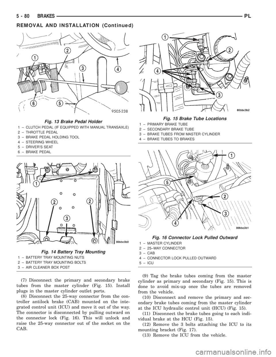
(7) Disconnect the primary and secondary brake
tubes from the master cylinder (Fig. 15). Install
plugs in the master cylinder outlet ports.
(8) Disconnect the 25-way connector from the con-
troller antilock brake (CAB) mounted on the inte-
grated control unit (ICU) and move it out of the way.
The connector is disconnected by pulling outward on
the connector lock (Fig. 16). This will unlock and
raise the 25-way connector out of the socket on the
CAB.(9) Tag the brake tubes coming from the master
cylinder as primary and secondary (Fig. 15). This is
done to avoid mix-up once the tubes are removed
from the vehicle.
(10) Disconnect and remove the primary and sec-
ondary brake tubes coming from the master cylinder
at the ICU hydraulic control unit (HCU) (Fig. 15).
(11) Disconnect the brake tubes going to each indi-
vidual brake at the HCU (Fig. 15).
(12) Remove the 3 bolts attaching the ICU to its
mounting bracket (Fig. 17).
(13) Remove the ICU from the vehicle.
Fig. 13 Brake Pedal Holder
1 ± CLUTCH PEDAL (IF EQUIPPED WITH MANUAL TRANSAXLE)
2 ± THROTTLE PEDAL
3 ± BRAKE PEDAL HOLDING TOOL
4 ± STEERING WHEEL
5 ± DRIVER'S SEAT
6 ± BRAKE PEDAL
Fig. 14 Battery Tray Mounting
1 ± BATTERY TRAY MOUNTING NUTS
2 ± BATTERY TRAY MOUNTING BOLTS
3 ± AIR CLEANER BOX POST
Fig. 15 Brake Tube Locations
1 ± PRIMARY BRAKE TUBE
2 ± SECONDARY BRAKE TUBE
3 ± BRAKE TUBES FROM MASTER CYLINDER
4 ± BRAKE TUBES TO BRAKES
Fig. 16 Connector Lock Pulled Outward
1 ± MASTER CYLINDER
2 ± 25±WAY CONNECTOR
3 ± CAB
4 ± CONNECTOR LOCK PULLED OUTWARD
5 ± ICU
5 - 80 BRAKESPL
REMOVAL AND INSTALLATION (Continued)
Page 160 of 1285
(14) Refer to DISASSEMBLY AND ASSEMBLY in
this section of this group for the procedure on sepa-
rating and reattaching the CAB to the HCU.
INSTALLATION
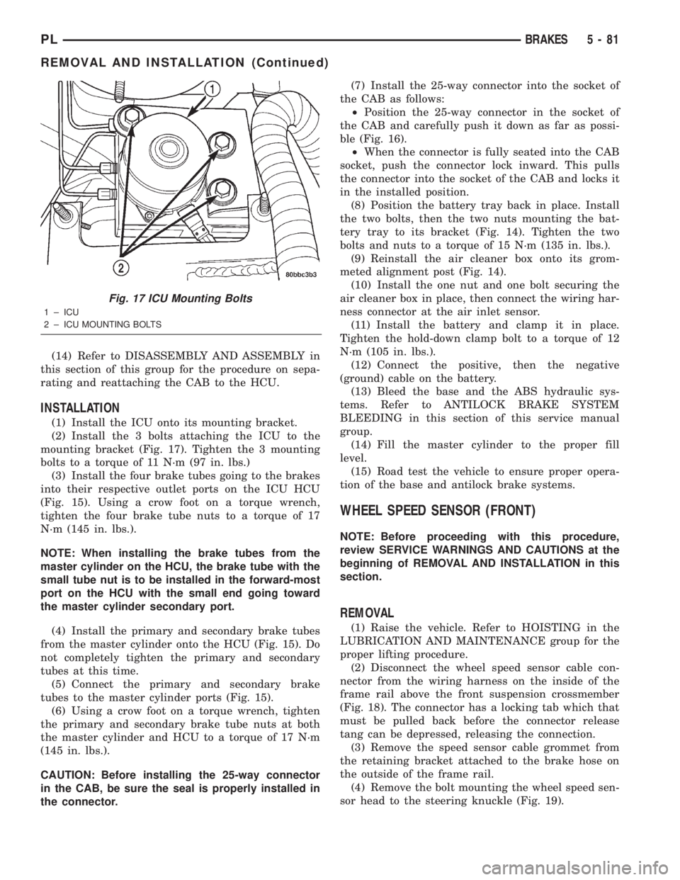
(1) Install the ICU onto its mounting bracket.
(2) Install the 3 bolts attaching the ICU to the
mounting bracket (Fig. 17). Tighten the 3 mounting
bolts to a torque of 11 N´m (97 in. lbs.)
(3) Install the four brake tubes going to the brakes
into their respective outlet ports on the ICU HCU
(Fig. 15). Using a crow foot on a torque wrench,
tighten the four brake tube nuts to a torque of 17
N´m (145 in. lbs.).
NOTE: When installing the brake tubes from the
master cylinder on the HCU, the brake tube with the
small tube nut is to be installed in the forward-most
port on the HCU with the small end going toward
the master cylinder secondary port.
(4) Install the primary and secondary brake tubes
from the master cylinder onto the HCU (Fig. 15). Do
not completely tighten the primary and secondary
tubes at this time.
(5) Connect the primary and secondary brake
tubes to the master cylinder ports (Fig. 15).
(6) Using a crow foot on a torque wrench, tighten
the primary and secondary brake tube nuts at both
the master cylinder and HCU to a torque of 17 N´m
(145 in. lbs.).
CAUTION: Before installing the 25-way connector
in the CAB, be sure the seal is properly installed in
the connector.(7) Install the 25-way connector into the socket of
the CAB as follows:
²Position the 25-way connector in the socket of
the CAB and carefully push it down as far as possi-
ble (Fig. 16).
²When the connector is fully seated into the CAB
socket, push the connector lock inward. This pulls
the connector into the socket of the CAB and locks it
in the installed position.
(8) Position the battery tray back in place. Install
the two bolts, then the two nuts mounting the bat-
tery tray to its bracket (Fig. 14). Tighten the two
bolts and nuts to a torque of 15 N´m (135 in. lbs.).
(9) Reinstall the air cleaner box onto its grom-
meted alignment post (Fig. 14).
(10) Install the one nut and one bolt securing the
air cleaner box in place, then connect the wiring har-
ness connector at the air inlet sensor.
(11) Install the battery and clamp it in place.
Tighten the hold-down clamp bolt to a torque of 12
N´m (105 in. lbs.).
(12) Connect the positive, then the negative
(ground) cable on the battery.
(13) Bleed the base and the ABS hydraulic sys-
tems. Refer to ANTILOCK BRAKE SYSTEM
BLEEDING in this section of this service manual
group.
(14) Fill the master cylinder to the proper fill
level.
(15) Road test the vehicle to ensure proper opera-
tion of the base and antilock brake systems.
WHEEL SPEED SENSOR (FRONT)
NOTE: Before proceeding with this procedure,
review SERVICE WARNINGS AND CAUTIONS at the
beginning of REMOVAL AND INSTALLATION in this
section.
REMOVAL
(1) Raise the vehicle. Refer to HOISTING in the
LUBRICATION AND MAINTENANCE group for the
proper lifting procedure.
(2) Disconnect the wheel speed sensor cable con-
nector from the wiring harness on the inside of the
frame rail above the front suspension crossmember
(Fig. 18). The connector has a locking tab which that
must be pulled back before the connector release
tang can be depressed, releasing the connection.
(3) Remove the speed sensor cable grommet from
the retaining bracket attached to the brake hose on
the outside of the frame rail.
(4) Remove the bolt mounting the wheel speed sen-
sor head to the steering knuckle (Fig. 19).
Fig. 17 ICU Mounting Bolts
1 ± ICU
2 ± ICU MOUNTING BOLTS
PLBRAKES 5 - 81
REMOVAL AND INSTALLATION (Continued)
Page 164 of 1285
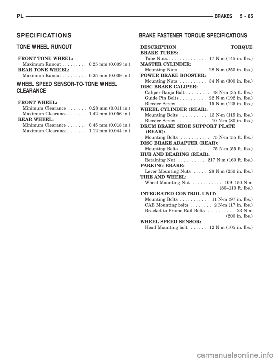
SPECIFICATIONS
TONE WHEEL RUNOUT
FRONT TONE WHEEL:
Maximum Runout.........0.25 mm (0.009 in.)
REAR TONE WHEEL:
Maximum Runout.........0.25 mm (0.009 in.)
WHEEL SPEED SENSOR-TO-TONE WHEEL
CLEARANCE
FRONT WHEEL:
Minimum Clearance.......0.28 mm (0.011 in.)
Maximum Clearance.......1.42 mm (0.056 in.)
REAR WHEEL:
Minimum Clearance.......0.45 mm (0.018 in.)
Maximum Clearance.......1.12 mm (0.044 in.)
BRAKE FASTENER TORQUE SPECIFICATIONS
DESCRIPTION TORQUE
BRAKE TUBES:
Tube Nuts............... 17N´m(145 in. lbs.)
MASTER CYLINDER:
Mounting Nuts.......... 28N´m(250 in. lbs.)
POWER BRAKE BOOSTER:
Mounting Nuts.......... 34N´m(300 in. lbs.)
DISC BRAKE CALIPER:
Caliper Banjo Bolt......... 48N´m(35ft.lbs.)
Guide Pin Bolts.......... 22N´m(192 in. lbs.)
Bleeder Screw........... 15N´m(125 in. lbs.)
WHEEL CYLINDER (REAR):
Mounting Bolts.......... 13N´m(115in.lbs.)
Bleeder Screw............ 10N´m(80in.lbs.)
DRUM BRAKE SHOE SUPPORT PLATE
(REAR):
Mounting Bolts........... 75N´m(55ft.lbs.)
DISC BRAKE ADAPTER (REAR):
Mounting Bolts........... 75N´m(55ft.lbs.)
HUB AND BEARING (REAR):
Retaining Nut.......... 217N´m(160 ft. lbs.)
PARKING BRAKE:
Lever Mounting Nuts..... 28N´m(250 in. lbs.)
TIRE AND WHEEL:
Wheel Mounting Nut...........109±150 N´m
(80±110 ft. lbs.)
INTEGRATED CONTROL UNIT:
Mounting Bolts........... 11N´m(97in.lbs.)
CAB Mounting bolts........ 2N´m(17in.lbs.)
Bracket-to-Frame Rail Bolts.......... 23N´m
(200 in. lbs.)
WHEEL SPEED SENSOR:
Head Mounting bolt...... 12N´m(105 in. lbs.)
PLBRAKES 5 - 85
Page 170 of 1285
DRIVE PLATE MISALIGNMENT
Common causes of misalignment are:
²Heat warping
²Mounting drive plate on a dirty crankshaft
flange
²Incorrect bolt tightening
²Improper seating on the crankshaft shoulder
²Loose crankshaft bolts
Clean the crankshaft flange before mounting the
drive plate. Dirt and grease on the flange surface
may misalign the flywheel, causing excessive runout.
Use new bolts when mounting drive plate to crank-
shaft. Tighten drive plate bolts to specified torque
only. Over-tightening can distort the drive plate hub
causing excessive runout.
CLUTCH CHATTER COMPLAINTS
For all clutch chatter complaints, do the following:
(1) Check for loose, misaligned, or broken engine
and transmission mounts. If present, they should be
corrected at this time. Test vehicle for chatter. If
chatter is gone, there is no need to go any further. If
chatter persists:
(2) Check to see if clutch cable routing is correct
and operates smoothly.
(3) Check for loose connections in drive train. Cor-
rect any problems and determine if clutch chatter
complaints have been satisfied. If not:
(4) Remove transaxle. See Group 21, Manual Tran-
saxle for procedure.
(5) Check to see if the release bearing is sticky or
binding. Replace bearing, if needed.
(6) Check linkage for excessive wear on the pivot
stud and fork fingers. Replace all worn parts.
(7) Check clutch assembly for contamination (dirt,
oil). Replace clutch assembly, if required.
(8) Check to see if the clutch disc hub splines are
damaged. Replace with new clutch assembly, if nec-
essary.
(9) Check input shaft splines for damage. Replace,
if necessary.
(10) Check for uneven wear on clutch fingers.
(11) Check for broken clutch cover diaphragm
spring fingers. Replace with new clutch assembly, if
necessary.
CLASH±INTO±REVERSE COMPLAINTS
Certain NV T350 (A-578) manual transaxles are
equipped with a reverse brake. It prevents clash
when shifting into reverse, but only if the vehicle is
not moving. See Group 21, Transaxle for further
diagnosis.
(1) Depress clutch pedal to floor and hold. After
three seconds, shift to reverse. If clash is present,
clutch has excessive spin time, and the reverse brake
may not be functioning.(2) Remove transaxle. See Group 21, Manual Tran-
saxle for procedure.
(3) Check the input shaft spline, clutch disc
splines, and release bearing for dry rust. If present,
clean rust off and apply a light coat of bearing grease
to the input shaft splines. Apply grease on the input
shaft splines only where the clutch disc slides. Verify
that the clutch disc slides freely along the input shaft
spline.
(4) Check to see if the clutch disc hub splines are
damaged, and replace with new clutch assembly if
required.
(5) Check the input shaft for damaged splines.
Replace as necessary.
(6) Check for broken clutch cover diaphragm
spring fingers.
(7) Install clutch assembly and transaxle.
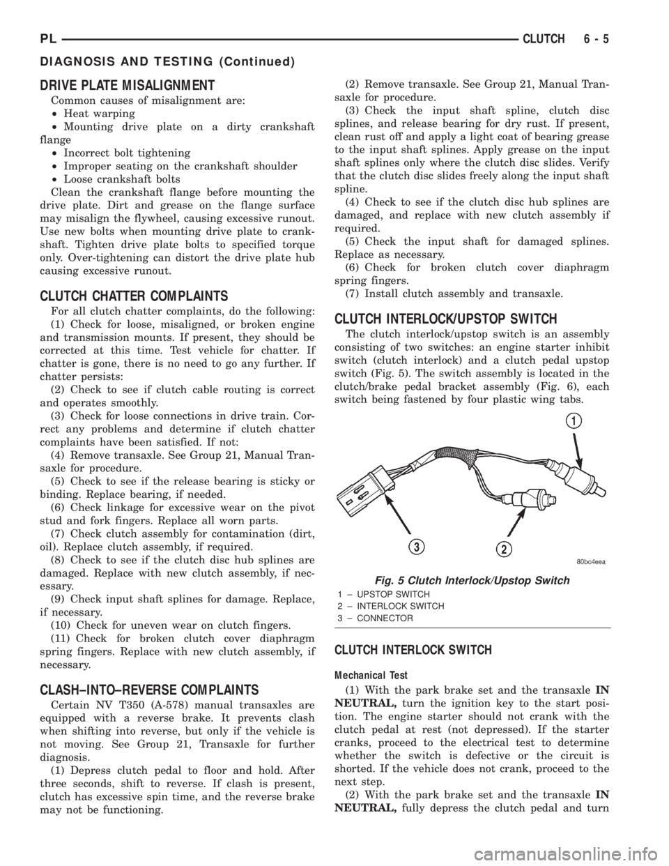
CLUTCH INTERLOCK/UPSTOP SWITCH
The clutch interlock/upstop switch is an assembly
consisting of two switches: an engine starter inhibit
switch (clutch interlock) and a clutch pedal upstop
switch (Fig. 5). The switch assembly is located in the
clutch/brake pedal bracket assembly (Fig. 6), each
switch being fastened by four plastic wing tabs.
CLUTCH INTERLOCK SWITCH
Mechanical Test
(1) With the park brake set and the transaxleIN
NEUTRAL,turn the ignition key to the start posi-
tion. The engine starter should not crank with the
clutch pedal at rest (not depressed). If the starter
cranks, proceed to the electrical test to determine
whether the switch is defective or the circuit is
shorted. If the vehicle does not crank, proceed to the
next step.
(2) With the park brake set and the transaxleIN
NEUTRAL,fully depress the clutch pedal and turn
Fig. 5 Clutch Interlock/Upstop Switch
1 ± UPSTOP SWITCH
2 ± INTERLOCK SWITCH
3 ± CONNECTOR
PLCLUTCH 6 - 5
DIAGNOSIS AND TESTING (Continued)
Page 174 of 1285
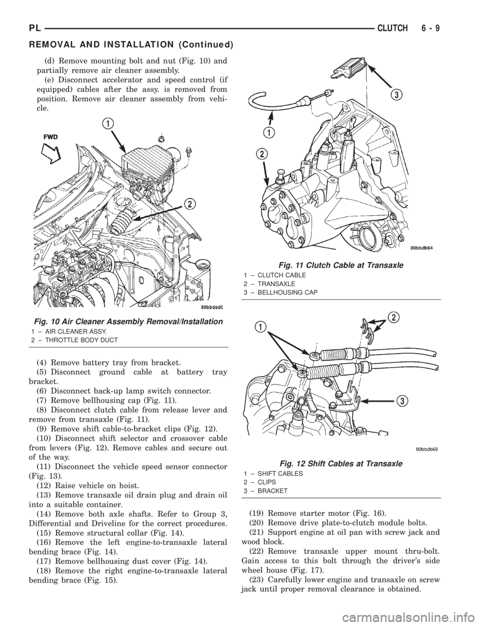
(d) Remove mounting bolt and nut (Fig. 10) and
partially remove air cleaner assembly.
(e) Disconnect accelerator and speed control (if
equipped) cables after the assy. is removed from
position. Remove air cleaner assembly from vehi-
cle.
(4) Remove battery tray from bracket.
(5) Disconnect ground cable at battery tray
bracket.
(6) Disconnect back-up lamp switch connector.
(7) Remove bellhousing cap (Fig. 11).
(8) Disconnect clutch cable from release lever and
remove from transaxle (Fig. 11).
(9) Remove shift cable-to-bracket clips (Fig. 12).
(10) Disconnect shift selector and crossover cable
from levers (Fig. 12). Remove cables and secure out
of the way.
(11) Disconnect the vehicle speed sensor connector
(Fig. 13).
(12) Raise vehicle on hoist.
(13) Remove transaxle oil drain plug and drain oil
into a suitable container.
(14) Remove both axle shafts. Refer to Group 3,
Differential and Driveline for the correct procedures.
(15) Remove structural collar (Fig. 14).
(16) Remove the left engine-to-transaxle lateral
bending brace (Fig. 14).
(17) Remove bellhousing dust cover (Fig. 14).
(18) Remove the right engine-to-transaxle lateral
bending brace (Fig. 15).(19) Remove starter motor (Fig. 16).
(20) Remove drive plate-to-clutch module bolts.
(21) Support engine at oil pan with screw jack and
wood block.
(22) Remove transaxle upper mount thru-bolt.
Gain access to this bolt through the driver's side
wheel house (Fig. 17).
(23) Carefully lower engine and transaxle on screw
jack until proper removal clearance is obtained.
Fig. 10 Air Cleaner Assembly Removal/Installation
1 ± AIR CLEANER ASSY.
2 ± THROTTLE BODY DUCTFWD
Fig. 11 Clutch Cable at Transaxle
1 ± CLUTCH CABLE
2 ± TRANSAXLE
3 ± BELLHOUSING CAP
Fig. 12 Shift Cables at Transaxle
1 ± SHIFT CABLES
2 ± CLIPS
3 ± BRACKET
PLCLUTCH 6 - 9
REMOVAL AND INSTALLATION (Continued)
Page 178 of 1285
cover and flywheel. Heat buildup caused by slippage
can bake the oil residue onto the components. This
glaze-like residue ranges in color from amber to
black.
GREASE CONTAMINATION
Grease contamination is usually a product of over-
lubrication. During clutch service, apply only a small
amount of grease to the input shaft splines. Excess
grease may be thrown off during operation, contami-
nating the disc.
ROAD SPLASH/WATER CONTAMINATION
Road splash contamination is usually caused by
driving the vehicle through deep water puddles.
Water can be forced into the clutch housing, causing
clutch components to become contaminated. Facing of
disc will absorb moisture and bond to the flywheel
and/or, pressure plate, if vehicle is allowed to stand
for some time before use. If this condition occurs,
replacement of clutch assembly may be required.
Drive the vehicle until normal clutch operating tem-
perature has been obtained. This will dry off disc
assembly, pressure plate, and flywheel.
CLEANING PRECAUTIONS
Condensation from steam vapors tend to accumu-
late on the internal clutch mechanism when the vehi-
cle is steam cleaned. Facing of disc will absorb
moisture and will bond to flywheel and/or pressure
plate, if vehicle is allowed to stand for some time
before use. If this condition occurs, it may require
replacement of clutch assembly. After cleaning, drive
the vehicle to its normal clutch operating tempera-
ture. This will dry off disc assembly, pressure plate,
and flywheel.
SPECIFICATIONS
TORQUE
DESCRIPTION TORQUE
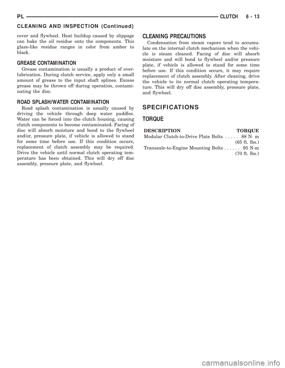
Modular Clutch-to-Drive Plate Bolts..... 88N´m
(65 ft. lbs.)
Transaxle-to-Engine Mounting Bolts...... 95N´m
(70 ft. lbs.)
PLCLUTCH 6 - 13
CLEANING AND INSPECTION (Continued)
Page 254 of 1285
INSTRUMENT CLUSTER LAMPS
WARNINGS/INDICATORS
The instrument cluster warning/indicator lamps
are all serviceable Light Emitting Diodes (LED's).
The instrument cluster must first be removed, refer
to Instrument Cluster Removal and Installation in
this section, and then the defective LED just turns
out with needle nose pliers.
ILLUMINATION LAMPS
The high beam indicator, turn signals, and illumi-
nation bulbs are also serviceable. The instrument
cluster must first be removed, refer to Instrument
Cluster Removal and Installation in this section, and
then the defective bulb and socket turns out. The
bulb locations are printed on the back cover of the
instrument cluster.
INSTRUMENT PANEL ASSEMBLY
REMOVAL
(1) Disconnect and isolate the battery negative
cable (Fig. 6).
(2) Push seats back to their full back position.
(3) Using a trim stick (special tool #C-4755), gently
pry out on left and right A-pillar trim moldings and
remove.
(4) Remove top cover. Refer to Top Cover Removal
and Installation in this section.
(5) Gently pull up on cluster bezel and remove
from vehicle.
(6) Gently pull rearward on left lower instrument
panel cover and remove from vehicle.
CAUTION: Lock the steering wheel in the straight
ahead position. This will prevent clockspring dam-
age when the steering wheel rotates freely.
(7) Remove steering column. Refer to Group 19
Steering, Steering Column Removal and Installation.
(8) Remove left and right instrument panel end-
caps.
(9) Remove left and right cowl side panels.
(10) Remove center console. Refer to Group 23
Body, Center Console Removal and Installation.
(11) Depress the sides of the Data Link Connector
(DLC) and remove from instrument panel reinforce-
ment.
(12) Remove four bulkhead instrument panel
retaining screws.
(13) Remove two bolts on top of the brake pedal
support bracket.
(14) Remove two center support mounting bolts.
(15) Remove left and right A-pillar mounting bolts,
two on each side.(16) Disconnect right side antenna connector.
(17) Remove left and right A-pillar door harness
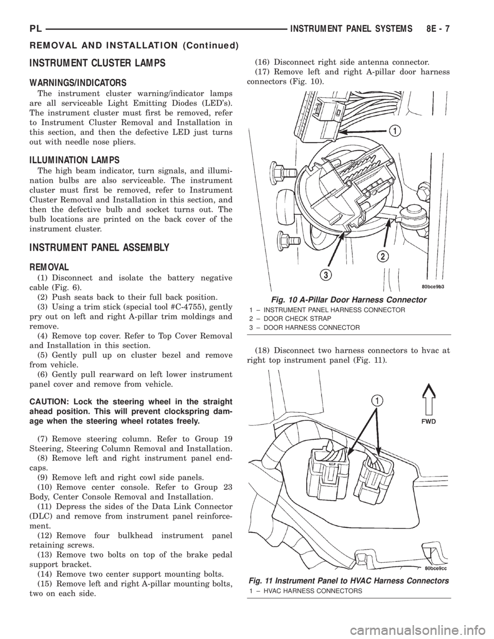
connectors (Fig. 10).
(18) Disconnect two harness connectors to hvac at
right top instrument panel (Fig. 11).
Fig. 10 A-Pillar Door Harness Connector
1 ± INSTRUMENT PANEL HARNESS CONNECTOR
2 ± DOOR CHECK STRAP
3 ± DOOR HARNESS CONNECTOR
Fig. 11 Instrument Panel to HVAC Harness Connectors
1 ± HVAC HARNESS CONNECTORS
PLINSTRUMENT PANEL SYSTEMS 8E - 7
REMOVAL AND INSTALLATION (Continued)
Page 263 of 1285
(1) Disconnect the negative battery cable.
(2) Remove the floor console. Refer to Group 23,
Body for the procedure.
(3) Remove the right and left side instrument
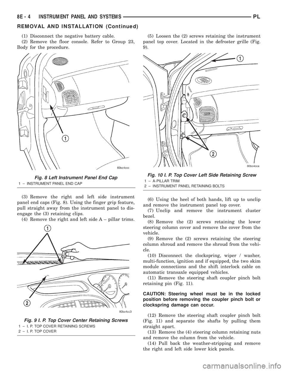
panel end caps (Fig. 8). Using the finger grip feature,
pull straight away from the instrument panel to dis-
engage the (3) retaining clips.
(4) Remove the right and left side A ± pillar trims.(5) Loosen the (2) screws retaining the instrument
panel top cover. Located in the defroster grille (Fig.
9).
(6) Using the heel of both hands, lift up to unclip
and remove the instrument panel top cover.
(7) Unclip and remove the instrument cluster
bezel.
(8) Remove the (2) screws retaining the lower
steering column cover and remove the cover from the
vehicle.
(9) Remove the (2) screws retaining the steering
column shroud and remove the shroud from the vehi-
cle.
(10) Disconnect the clockspring, wiper / washer,
multi-function, ignition and if equipped, the two skim
module connections and the shift interlock cable on
automatic transaxle equipped vehicles.
(11) Remove the steering shaft coupler pinch bolt
retaining pin (Fig. 11).
CAUTION: Steering wheel must be in the locked
position before removing the coupler pinch bolt or
clockspring damage can occur.
(12) Remove the steering shaft coupler pinch bolt
(Fig. 11) and separate the shafts by pulling them
straight apart.
(13) Remove the (4) steering column retaining nuts
and remove the column from the vehicle.
(14) Pull back the weather-stripping and remove
the right and left side lower kick panels.
Fig. 8 Left Instrument Panel End Cap
1 ± INSTRUMENT PANEL END CAP
Fig. 9 I. P. Top Cover Center Retaining Screws
1 ± I. P. TOP COVER RETAINING SCREWS
2 ± I. P. TOP COVER
Fig. 10 I. P. Top Cover Left Side Retaining Screw
1 ± A-PILLAR TRIM
2 ± INSTRUMENT PANEL RETAINING BOLTS
8E - 4 INSTRUMENT PANEL AND SYSTEMSPL
REMOVAL AND INSTALLATION (Continued)