DODGE NEON 2000 Service Repair Manual
Manufacturer: DODGE, Model Year: 2000, Model line: NEON, Model: DODGE NEON 2000Pages: 1285, PDF Size: 29.42 MB
Page 891 of 1285
(2) Ensuring that the installer and the pulley
remain aligned with pump shaft, turn the installer
outer nut and force the pulley onto the power steer-
ing pump shaft until it is flush with the end of the
pump shaft. Once the pulley is flush with the end of
the shaft, the installer outer nut will no longer be
able to turn.
(3) Remove the installer from the power steering
pump.
(4) Install the power steering pump back on the
engine. Refer to POWER STEERING PUMP in
REMOVAL AND INSTALLATION for the required
procedure.
SPECIFICATIONS
POWER STEERING PUMP FLOW
SPECIFICATIONS
Power Steering Pump Flow:
At 1500 RPM And Minimum
Pressure . . 4.2 to 4.9 Liters/Min (1.1 to 1.3 GPM)
Control Valve Pressure
Relief.....9308 to 9998 kPa (1350 to 1450 psi)
POWER STEERING FASTENER TORQUE
SPECIFICATIONS
DESCRIPTION TORQUE
POWER STEERING HOSE:
Tube Nuts............... 34N´m(25ft.lbs.)
Hose Routing Clip Bolt.... 12N´m(105 in. lbs.)
POWER STEERING COOLER:
Mounting Screws.......... 10N´m(90in.lbs.)
POWER STEERING FLUID PRESSURE
SWITCH:
Switch................... 8N´m(70in.lbs.)
POWER STEERING PUMP:
Pressure Hose Tube Nut.... 34N´m(25ft.lbs.)
Pressure Fitting........... 88N´m(65ft.lbs.)
Front Mounting Bolts..... 28N´m(250 in. lbs.)
Rear Mounting Bolt....... 28N´m(250 in. lbs.)
Rear Support Bracket To Engine Bolts . . 54 N´m
(40 ft. lbs.)
SPECIAL TOOLS
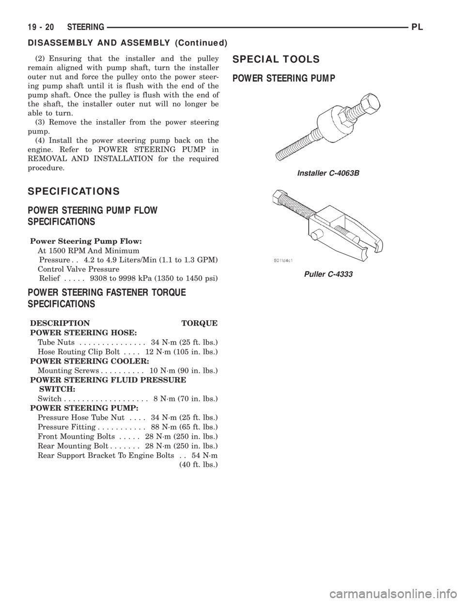
POWER STEERING PUMP
Installer C-4063B
Puller C-4333
19 - 20 STEERINGPL
DISASSEMBLY AND ASSEMBLY (Continued)
Page 892 of 1285
STEERING GEAR
TABLE OF CONTENTS
page page
DESCRIPTION AND OPERATION
POWER STEERING GEAR..................21
REMOVAL AND INSTALLATION
SERVICE WARNINGS AND CAUTIONS........22
POWER STEERING GEAR..................22
OUTER TIE ROD.........................26SPECIFICATIONS
POWER STEERING GEAR FASTENER
TORQUE SPECIFICATIONS...............28
SPECIAL TOOLS
POWER STEERING GEAR..................28
DESCRIPTION AND OPERATION
POWER STEERING GEAR
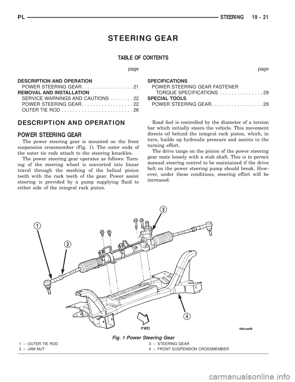
The power steering gear is mounted on the front
suspension crossmember (Fig. 1). The outer ends of
the outer tie rods attach to the steering knuckles.
The power steering gear operates as follows: Turn-
ing of the steering wheel is converted into linear
travel through the meshing of the helical pinion
teeth with the rack teeth of the gear. Power assist
steering is provided by a pump supplying fluid to
either side of the integral rack piston.Road feel is controlled by the diameter of a torsion
bar which initially steers the vehicle. This movement
directs oil behind the integral rack piston, which, in
turn, builds up hydraulic pressure and assists in the
turning effort.
The drive tangs on the pinion of the power steering
gear mate loosely with a stub shaft. This is to permit
manual steering control to be maintained if the drive
belt on the power steering pump should break. How-
ever, under these conditions, steering effort will be
increased.
Fig. 1 Power Steering Gear
1 ± OUTER TIE ROD
2 ± JAM NUT3 ± STEERING GEAR
4 ± FRONT SUSPENSION CROSSMEMBER
PLSTEERING 19 - 21
Page 893 of 1285
NOTE: The power steering gear should not be ser-
viced or adjusted. If a malfunction or oil leak occurs
with the steering gear, the complete steering gear
needs to be replaced.
REMOVAL AND INSTALLATION
SERVICE WARNINGS AND CAUTIONS
WARNING: POWER STEERING FLUID, ENGINE
PARTS AND EXHAUST SYSTEM MAY BE
EXTREMELY HOT IF ENGINE HAS BEEN RUNNING.
DO NOT START ENGINE WITH ANY LOOSE OR DIS-
CONNECTED HOSES. DO NOT ALLOW HOSES TO
TOUCH HOT EXHAUST MANIFOLD OR CATALYST.
WARNING: FLUID LEVEL SHOULD BE CHECKED
WITH THE ENGINE OFF TO PREVENT PERSONAL
INJURY FROM MOVING PARTS.
CAUTION: When the system is open, cap all open
ends of the hoses, power steering pump fittings or
power steering gear ports to prevent entry of for-
eign material into the components.
NOTE: Do not use any type of automatic transmis-
sion fluid in the power steering system.
POWER STEERING GEAR
NOTE: Before proceeding with this removal and
installation procedure, review SERVICE WARNINGS
AND CAUTIONS at the beginning of REMOVAL AND
INSTALLATION in this section.
REMOVAL
(1) Place the steering wheel in the STRAIGHT-
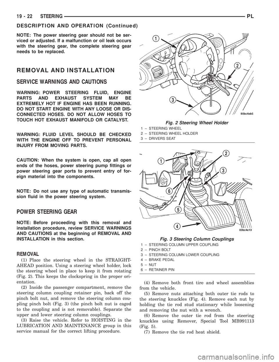
AHEAD position. Using a steering wheel holder, lock
the steering wheel in place to keep it from rotating
(Fig. 2). This keeps the clockspring in the proper ori-
entation.
(2) Inside the passenger compartment, remove the
steering column coupling retainer pin, back off the
pinch bolt nut, and remove the steering column cou-
pling pinch bolt (Fig. 3) (the pinch bolt nut is caged
to the coupling and is not removable). Separate the
upper and lower steering column couplings.
(3) Raise the vehicle. Refer to HOISTING in the
LUBRICATION AND MAINTENANCE group in this
service manual for the correct lifting procedure.(4) Remove both front tire and wheel assemblies
from the vehicle.
(5) Remove nuts attaching both outer tie rods to
the steering knuckles (Fig. 4). Remove each nut by
holding the tie rod stud stationary while loosening
and removing the nut with a wrench.
(6) Remove the outer tie rod from the steering
knuckles using Remover, Special Tool MB991113
(Fig. 5).
(7) Remove the tie rod heat shield.
Fig. 2 Steering Wheel Holder
1 ± STEERING WHEEL
2 ± STEERING WHEEL HOLDER
3 ± DRIVERS SEAT
Fig. 3 Steering Column Couplings
1 ± STEERING COLUMN UPPER COUPLING
2 ± PINCH BOLT
3 ± STEERING COLUMN LOWER COUPLING
4 ± BRAKE PEDAL
5 ± NUT
6 ± RETAINER PIN
19 - 22 STEERINGPL
DESCRIPTION AND OPERATION (Continued)
Page 894 of 1285
(8) Release the locking tab on the wiring harness
connector for the power steering fluid pressure
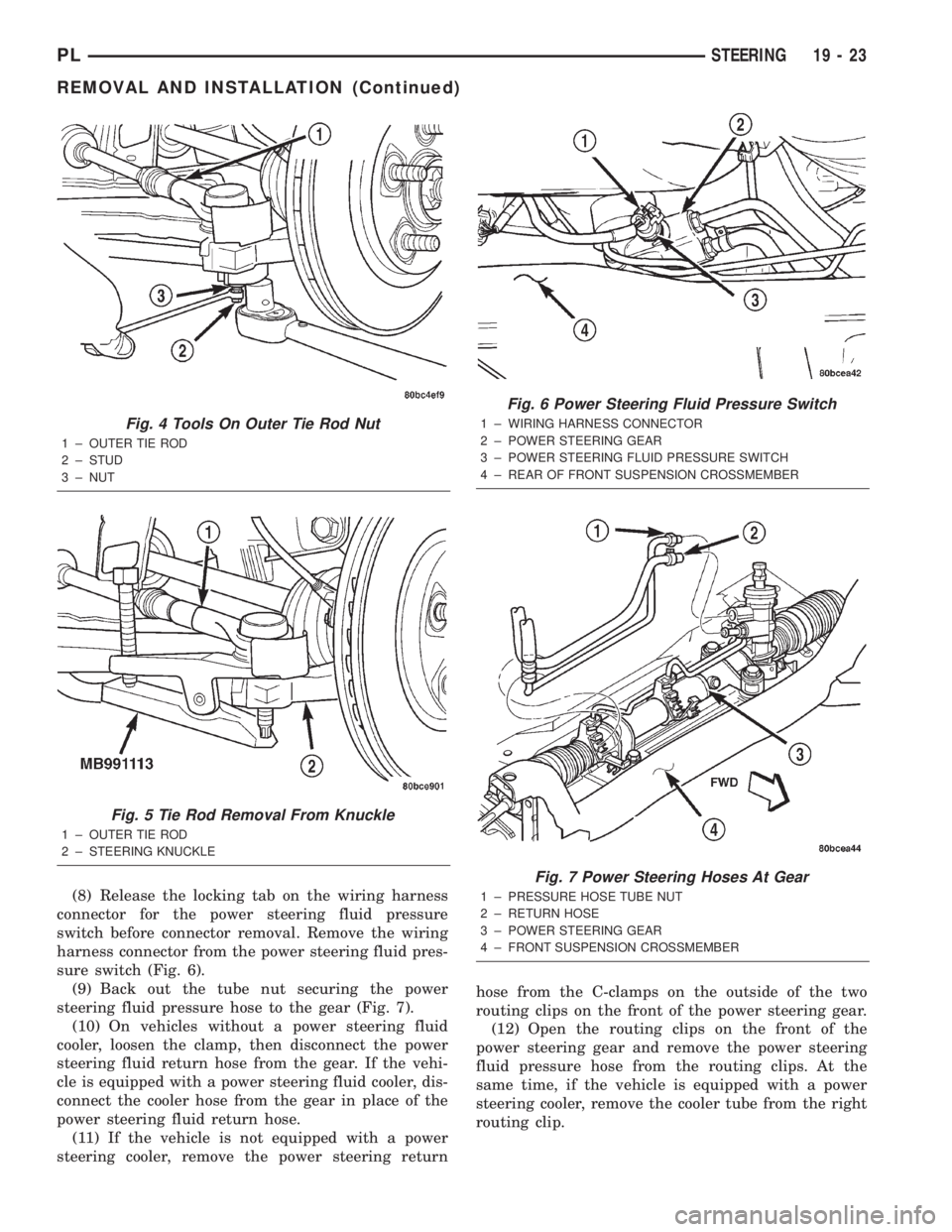
switch before connector removal. Remove the wiring
harness connector from the power steering fluid pres-
sure switch (Fig. 6).
(9) Back out the tube nut securing the power
steering fluid pressure hose to the gear (Fig. 7).
(10) On vehicles without a power steering fluid
cooler, loosen the clamp, then disconnect the power
steering fluid return hose from the gear. If the vehi-
cle is equipped with a power steering fluid cooler, dis-
connect the cooler hose from the gear in place of the
power steering fluid return hose.
(11) If the vehicle is not equipped with a power
steering cooler, remove the power steering returnhose from the C-clamps on the outside of the two
routing clips on the front of the power steering gear.
(12) Open the routing clips on the front of the
power steering gear and remove the power steering
fluid pressure hose from the routing clips. At the
same time, if the vehicle is equipped with a power
steering cooler, remove the cooler tube from the right
routing clip.
Fig. 4 Tools On Outer Tie Rod Nut
1 ± OUTER TIE ROD
2 ± STUD
3 ± NUT
Fig. 5 Tie Rod Removal From Knuckle
1 ± OUTER TIE ROD
2 ± STEERING KNUCKLE
Fig. 6 Power Steering Fluid Pressure Switch
1 ± WIRING HARNESS CONNECTOR
2 ± POWER STEERING GEAR
3 ± POWER STEERING FLUID PRESSURE SWITCH
4 ± REAR OF FRONT SUSPENSION CROSSMEMBER
Fig. 7 Power Steering Hoses At Gear
1 ± PRESSURE HOSE TUBE NUT
2 ± RETURN HOSE
3 ± POWER STEERING GEAR
4 ± FRONT SUSPENSION CROSSMEMBER
PLSTEERING 19 - 23
REMOVAL AND INSTALLATION (Continued)
Page 895 of 1285
(13) If the vehicle is equipped with a power steer-
ing fluid cooler, remove the two screws securing the
cooler to the front suspension crossmember. They are
located behind the cooler and can be accessed from
above. Allow the cooler to hang out of the way.
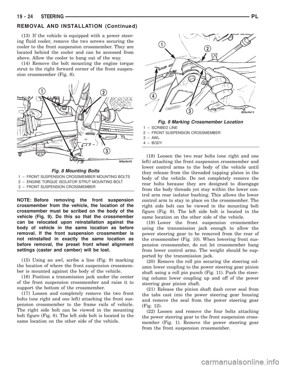
(14) Remove the bolt mounting the engine torque
strut to the right forward corner of the front suspen-
sion crossmember (Fig. 8).
NOTE: Before removing the front suspension
crossmember from the vehicle, the location of the
crossmember must be scribed on the body of the
vehicle (Fig. 9). Do this so that the crossmember
can be relocated upon reinstallation against the
body of vehicle in the same location as before
removal. If the front suspension crossmember is
not reinstalled in exactly the same location as
before removal, the preset front wheel alignment
settings (caster and camber) will be lost.
(15) Using an awl, scribe a line (Fig. 9) marking
the location of where the front suspension crossmem-
ber is mounted against the body of the vehicle.
(16) Position a transmission jack under the center
of the front suspension crossmember and raise it to
support the bottom of the crossmember.
(17) Loosen and completely remove the two front
bolts (one right and one left) attaching the front sus-
pension crossmember to the frame rails of vehicle.
The right side bolt can be viewed in the mounting
bolt figure (Fig. 8). The left side bolt is located in the
same location on the other side of the vehicle.(18) Loosen the two rear bolts (one right and one
left) attaching the front suspension crossmember and
lower control arms to the body of the vehicle until
they release from the threaded tapping plates in the
body of the vehicle. Do not completely remove the
rear bolts because they are designed to disengage
from the body threads yet stay within the lower con-
trol arm rear isolator bushing. This allows the lower
control arm to stay in place on the crossmember. The
right side bolt can be viewed in the mounting bolt
figure (Fig. 8). The left side bolt is located in the
same location on the other side of the vehicle.
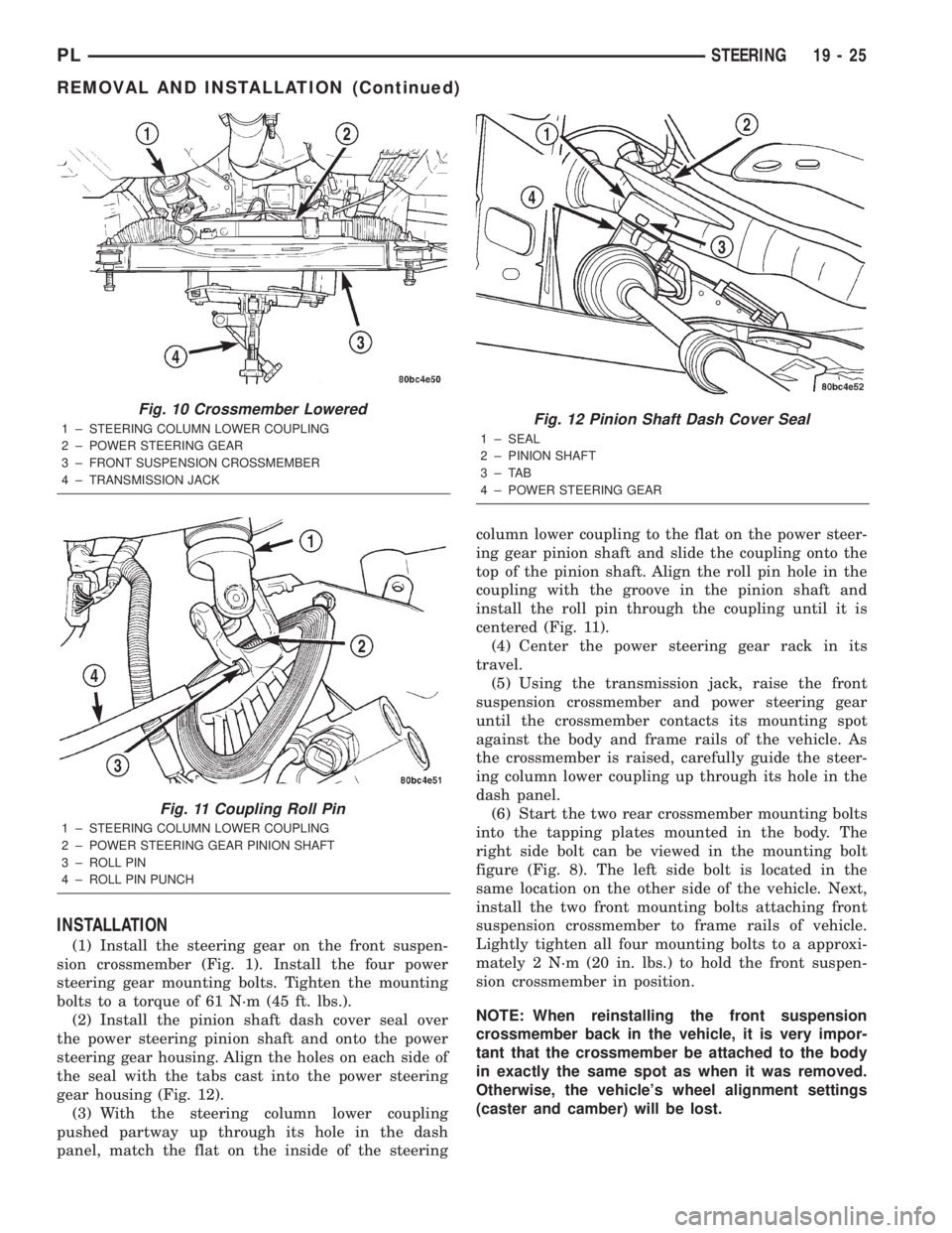
(19) Lower the front suspension crossmember
using the transmission jack enough to allow the
power steering gear to be removed from the rear of
the crossmember (Fig. 10). When lowering front sus-
pension crossmember, do not let crossmember hang
from lower control arms. The weight should be sup-
ported by the transmission jack.
(20) Remove the roll pin securing the steering col-
umn lower coupling to the power steering gear pinion
shaft using a roll pin punch (Fig. 11). Push the steer-
ing column lower coupling up and off of the power
steering gear pinion shaft.
(21) Release the pinion shaft dash cover seal from
the tabs cast into the power steering gear housing
and remove the seal from the power steering gear
(Fig. 12).
(22) Loosen and remove the four bolts attaching
the power steering gear to the front suspension cross-
member (Fig. 1). Remove the power steering gear
from the front suspension crossmember.
Fig. 8 Mounting Bolts
1 ± FRONT SUSPENSION CROSSMEMBER MOUNTING BOLTS
2 ± ENGINE TORQUE ISOLATOR STRUT MOUNTING BOLT
3 ± FRONT SUSPENSION CROSSMEMBER
Fig. 9 Marking Crossmember Location
1 ± SCRIBED LINE
2 ± FRONT SUSPENSION CROSSMEMBER
3±AWL
4 ± BODY
19 - 24 STEERINGPL
REMOVAL AND INSTALLATION (Continued)
Page 896 of 1285
INSTALLATION
(1) Install the steering gear on the front suspen-
sion crossmember (Fig. 1). Install the four power
steering gear mounting bolts. Tighten the mounting
bolts to a torque of 61 N´m (45 ft. lbs.).
(2) Install the pinion shaft dash cover seal over
the power steering pinion shaft and onto the power
steering gear housing. Align the holes on each side of
the seal with the tabs cast into the power steering
gear housing (Fig. 12).
(3) With the steering column lower coupling
pushed partway up through its hole in the dash
panel, match the flat on the inside of the steeringcolumn lower coupling to the flat on the power steer-
ing gear pinion shaft and slide the coupling onto the
top of the pinion shaft. Align the roll pin hole in the
coupling with the groove in the pinion shaft and
install the roll pin through the coupling until it is
centered (Fig. 11).
(4) Center the power steering gear rack in its
travel.
(5) Using the transmission jack, raise the front
suspension crossmember and power steering gear
until the crossmember contacts its mounting spot
against the body and frame rails of the vehicle. As
the crossmember is raised, carefully guide the steer-
ing column lower coupling up through its hole in the
dash panel.
(6) Start the two rear crossmember mounting bolts
into the tapping plates mounted in the body. The
right side bolt can be viewed in the mounting bolt
figure (Fig. 8). The left side bolt is located in the
same location on the other side of the vehicle. Next,
install the two front mounting bolts attaching front
suspension crossmember to frame rails of vehicle.
Lightly tighten all four mounting bolts to a approxi-
mately 2 N´m (20 in. lbs.) to hold the front suspen-
sion crossmember in position.
NOTE: When reinstalling the front suspension
crossmember back in the vehicle, it is very impor-
tant that the crossmember be attached to the body
in exactly the same spot as when it was removed.
Otherwise, the vehicle's wheel alignment settings
(caster and camber) will be lost.
Fig. 10 Crossmember Lowered
1 ± STEERING COLUMN LOWER COUPLING
2 ± POWER STEERING GEAR
3 ± FRONT SUSPENSION CROSSMEMBER
4 ± TRANSMISSION JACK
Fig. 11 Coupling Roll Pin
1 ± STEERING COLUMN LOWER COUPLING
2 ± POWER STEERING GEAR PINION SHAFT
3 ± ROLL PIN
4 ± ROLL PIN PUNCH
Fig. 12 Pinion Shaft Dash Cover Seal
1 ± SEAL
2 ± PINION SHAFT
3±TAB
4 ± POWER STEERING GEAR
PLSTEERING 19 - 25
REMOVAL AND INSTALLATION (Continued)
Page 897 of 1285
(7) Using a soft face hammer, tap the front suspen-
sion crossmember back-and-forth or side-to-side until
it is aligned with the previously scribed positioning
marks on the body of the vehicle (Fig. 9). Once the
front suspension crossmember is correctly positioned,
tighten the rear two crossmember (and rear lower
control arm) mounting bolts to a torque of 203 N´m
(150 ft. lbs.), then tighten the front two crossmember
mounting bolts to a torque of 142 N´m (105 ft. lbs.).
(8) Fasten the engine torque strut to the right for-
ward corner of the front suspension crossmember
using its mounting bolt (Fig. 8). Follow the procedure
described in the ENGINE service manual group to
properly align and tighten the torque strut and it's
mounting bolts.
(9) Using a lint free towel, wipe clean the open
power steering hose ends and the power steering
gear ports. Replace the pressure hose used O-ring
with new. Lubricate the O-ring with power steering
fluid.
(10) Attach the power steering fluid pressure hose
to it's port on the power steering gear (Fig. 7). Start
the tube nut threads into the gear, but do not tighten
them at this time. On vehicles equipped with a power
steering fluid cooler, reconnect the cooler line to the
gear in place of the power steering fluid return hose.
(11) Open the routing clips on the front of the
steering gear housing and install the power steering
fluid pressure hose into the routing clips.
(12) On vehicles equipped with a power steering
fluid cooler, place the cooler in mounting position and
snap the cooler tube going to the gear into the right
routing clip.
(13) Close both routing clips.
(14) Tighten the power steering fluid pressure
hose tube nut at the gear to a torque of 34 N´m (25
ft. lbs.).
(15) If the vehicle is equipped with a power steer-
ing fluid cooler, install the two screws securing the
cooler to the front suspension crossmember. They are
located behind the cooler.
(16) On vehicle's with a power steering fluid cooler,
place the hose clamp on the hose far enough from the
end to clear the steel fitting on the gear. Do the same
for the fluid return hose on a vehicle that is not
equipped with a cooler.
(17) Push either hose listed in the above step onto
the steel fitting, then move and secure the clamp on
the hose past the bead on the steel fitting in the
steering gears outlet port (Fig. 7).
(18) Route the fluid return hose along the front of
the steering gear, clipping it into place in the
C-clamps on the outside of the routing clips on the
front of the power steering gear housing.
(19) Reconnect the wiring harness connector from
the power steering fluid pressure switch (Fig. 6). Besure the locking tab on the wiring harness connector
is securely latched.
(20) Perform the following to each outer tie rod:
²Place the tie rod heat shield on the knuckle's
steering arm, aligning the hole in the shield with the
hole in the knuckle and the tangs on the outside of
the shield with the outside configuration of the steer-
ing arm. The shield should now be facing outboard,
away from the power steering gear and tie rod (Fig.
4).
²Attach the outer tie rod end to its steering
knuckle.
²Start the attaching nut onto the stud of the
outer tie rod.
²While holding the stud of the tie rod stationary
with a wrench, tighten the attaching nut (Fig. 4).
²Using a crowfoot wrench attached to a torque
wrench, tighten the attaching nut to 55 N´m (40 ft.
lbs.).
(21) Install the tire and wheel assemblies back on
vehicle. Tighten the wheel mounting nuts to 135 N´m
(100 ft. lbs.) torque.
(22) Lower the vehicle to ground level.
(23) Install the dash-to-lower coupling seal in
place over the lower coupling's plastic collar.
NOTE: Verify that grease is present on the lip of
the dash-to-coupling seal where it contacts the cou-
pling's plastic collar.
(24) Inside the passenger compartment, reconnect
the steering column lower coupling to the steering
column upper coupling (Fig. 3). Install the coupling
pinch bolt and tighten the pinch bolt nut to a torque
of 28 N´m (250 in. lbs.). Install the pinch bolt
retainer pin.
(25) Remove the steering wheel holder.
(26) While looking under the instrument panel at
the lower coupling, rotate the steering wheel back-
and-forth to verify that the lower coupling does not
squeak against the dash-to-coupling seal.
(27) Perform the POWER STEERING PUMP INI-
TIAL OPERATION service procedure which can be
found in the POWER STEERING PUMP section of
this group to properly fill and bleed the power steer-
ing system.
(28) Check for fluid leaks.
(29) Adjust the front toe setting on the vehicle.
Refer to WHEEL ALIGNMENT in the SUSPENSION
service manual group.
OUTER TIE ROD
REMOVAL
(1) Raise the vehicle. Refer to HOISTING in the
LUBRICATION AND MAINTENANCE group in this
service manual for the correct lifting procedure.
19 - 26 STEERINGPL
REMOVAL AND INSTALLATION (Continued)
Page 898 of 1285
(2) Remove the tire and wheel assembly from the
vehicle.
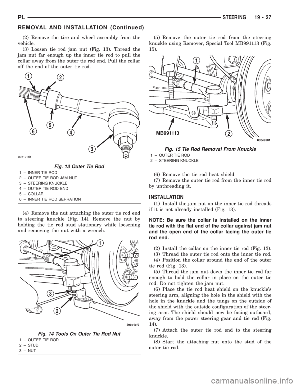
(3) Loosen tie rod jam nut (Fig. 13). Thread the
jam nut far enough up the inner tie rod to pull the
collar away from the outer tie rod end. Pull the collar
off the end of the outer tie rod.
(4) Remove the nut attaching the outer tie rod end
to steering knuckle (Fig. 14). Remove the nut by
holding the tie rod stud stationary while loosening
and removing the nut with a wrench.(5) Remove the outer tie rod from the steering
knuckle using Remover, Special Tool MB991113 (Fig.
15).
(6) Remove the tie rod heat shield.
(7) Remove the outer tie rod from the inner tie rod
by unthreading it.
INSTALLATION
(1) Install the jam nut on the inner tie rod threads
if it is not already installed (Fig. 13).
NOTE: Be sure the collar is installed on the inner
tie rod with the flat end of the collar against jam nut
and the open end of the collar facing the outer tie
rod end.
(2) Install the collar on the inner tie rod (Fig. 13).
(3) Thread the outer tie rod onto the inner tie rod.
(4) Position the collar around the end of the outer
tie rod (Fig. 13).
(5) Thread the jam nut down the inner tie rod far
enough to hold the collar in place on the outer tie
rod. Do not tighten the jam nut.
(6) Place the tie rod heat shield on the knuckle's
steering arm, aligning the hole in the shield with the
hole in the knuckle and the tangs on the outside of
the shield with the outside configuration of the steer-
ing arm. The shield should now be facing outboard,
away from the power steering gear and tie rod (Fig.
14).
(7) Attach the outer tie rod end to the steering
knuckle.
(8) Start the attaching nut onto the stud of the
outer tie rod.
Fig. 13 Outer Tie Rod
1 ± INNER TIE ROD
2 ± OUTER TIE ROD JAM NUT
3 ± STEERING KNUCKLE
4 ± OUTER TIE ROD END
5 ± COLLAR
6 ± INNER TIE ROD SERRATION
Fig. 14 Tools On Outer Tie Rod Nut
1 ± OUTER TIE ROD
2 ± STUD
3 ± NUT
Fig. 15 Tie Rod Removal From Knuckle
1 ± OUTER TIE ROD
2 ± STEERING KNUCKLE
PLSTEERING 19 - 27
REMOVAL AND INSTALLATION (Continued)
Page 899 of 1285
(9) While holding the stud of the tie rod stationary
with a wrench, tighten the attaching nut (Fig. 14).
(10) Using a crowfoot wrench attached to a torque
wrench, tighten the attaching nut to 75 N´m (55 ft.
lbs.).
(11) Install the tire and wheel assembly.
(12) Lower the vehicle.
(13) Adjust the front toe setting on the vehicle.
Refer to WHEEL ALIGNMENT in the SUSPENSION
service manual group.
SPECIFICATIONS
POWER STEERING GEAR FASTENER TORQUE
SPECIFICATIONS
DESCRIPTION TORQUE
FRONT SUSPENSION CROSSMEMBER:
Front Mounting Bolts..... 142N´m(105 ft. lbs.)
Rear Mounting Bolts..... 203N´m(150 ft. lbs.)
STEERING GEAR:
Mounting Bolts........... 61N´m(45ft.lbs.)
OUTER TIE ROD:
Steering Knuckle Nut...... 55N´m(40ft.lbs.)
TieRodJamNut .......... 75N´m(55ft.lbs.)
POWER STEERING HOSE:
Tube Nuts............... 34N´m(25ft.lbs.)
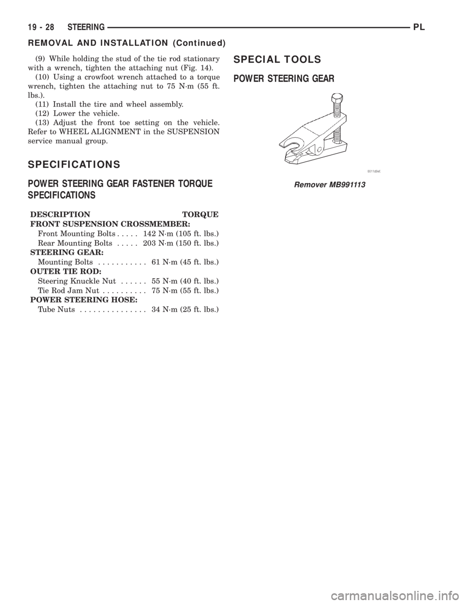
SPECIAL TOOLS
POWER STEERING GEAR
Remover MB991113
19 - 28 STEERINGPL
REMOVAL AND INSTALLATION (Continued)
Page 900 of 1285
STEERING COLUMN
TABLE OF CONTENTS
page page
DESCRIPTION AND OPERATION
STEERING COLUMN......................29
STEERING COLUMN LOWER COUPLING......29
DIAGNOSIS AND TESTING
STEERING COLUMN......................30
STEERING COLUMN LOWER COUPLING......30
REMOVAL AND INSTALLATION
SERVICE WARNINGS AND CAUTIONS........31STEERING COLUMN......................31
STEERING COLUMN LOWER COUPLING......38
SPECIFICATIONS
STEERING COLUMN FASTENER TORQUE
SPECIFICATIONS.......................41
DESCRIPTION AND OPERATION
STEERING COLUMN
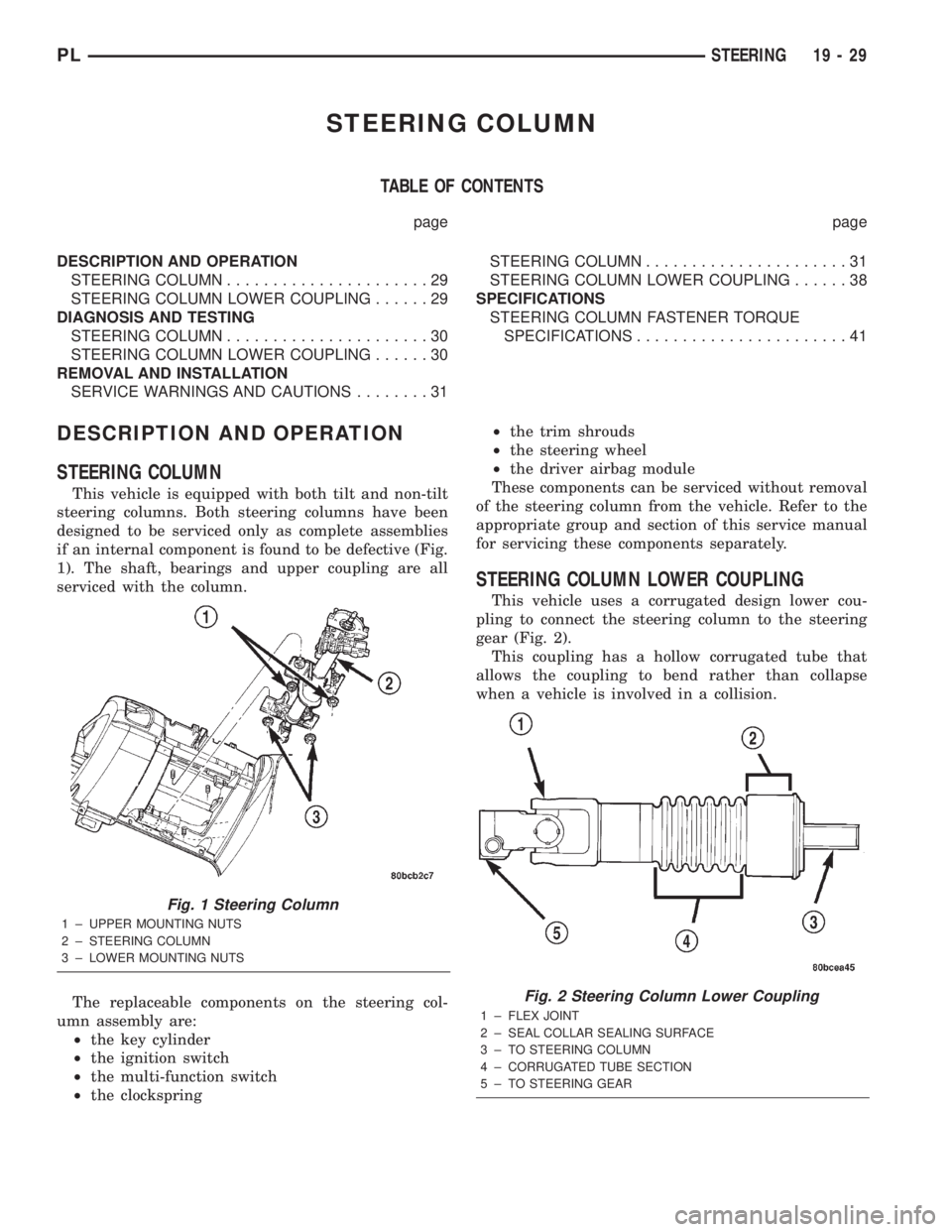
This vehicle is equipped with both tilt and non-tilt
steering columns. Both steering columns have been
designed to be serviced only as complete assemblies
if an internal component is found to be defective (Fig.
1). The shaft, bearings and upper coupling are all
serviced with the column.
The replaceable components on the steering col-
umn assembly are:
²the key cylinder
²the ignition switch
²the multi-function switch
²the clockspring²the trim shrouds
²the steering wheel
²the driver airbag module
These components can be serviced without removal
of the steering column from the vehicle. Refer to the
appropriate group and section of this service manual
for servicing these components separately.
STEERING COLUMN LOWER COUPLING
This vehicle uses a corrugated design lower cou-
pling to connect the steering column to the steering
gear (Fig. 2).
This coupling has a hollow corrugated tube that
allows the coupling to bend rather than collapse
when a vehicle is involved in a collision.
Fig. 1 Steering Column
1 ± UPPER MOUNTING NUTS
2 ± STEERING COLUMN
3 ± LOWER MOUNTING NUTS
Fig. 2 Steering Column Lower Coupling
1 ± FLEX JOINT
2 ± SEAL COLLAR SEALING SURFACE
3 ± TO STEERING COLUMN
4 ± CORRUGATED TUBE SECTION
5 ± TO STEERING GEAR
PLSTEERING 19 - 29