Coil DODGE RAM 1500 1998 2.G Workshop Manual
[x] Cancel search | Manufacturer: DODGE, Model Year: 1998, Model line: RAM 1500, Model: DODGE RAM 1500 1998 2.GPages: 2627
Page 9 of 2627
FASTENER USAGE
DESCRIPTION - FASTENER USAGE
WARNING: USE OF AN INCORRECT FASTENER
MAY RESULT IN COMPONENT DAMAGE OR PER-
SONAL INJURY.
Fasteners and torque specifications references in
this Service Manual are identified in metric and SAE
format.
During any maintenance or repair procedures, it is
important to salvage all fasteners (nuts, bolts, etc.)
for reassembly. If the fastener is not salvageable, a
fastener of equivalent specification must be used.
THREADED HOLE REPAIR
DESCRIPTION - THREADED HOLE REPAIR
Most stripped threaded holes can be repaired using
a Helicoilt. Follow the vehicle or Helicoiltrecommen-
dations for application and repair procedures.
METRIC SYSTEM
DESCRIPTION
The metric system is based on quantities of one,
ten, one hundred, one thousand and one million.
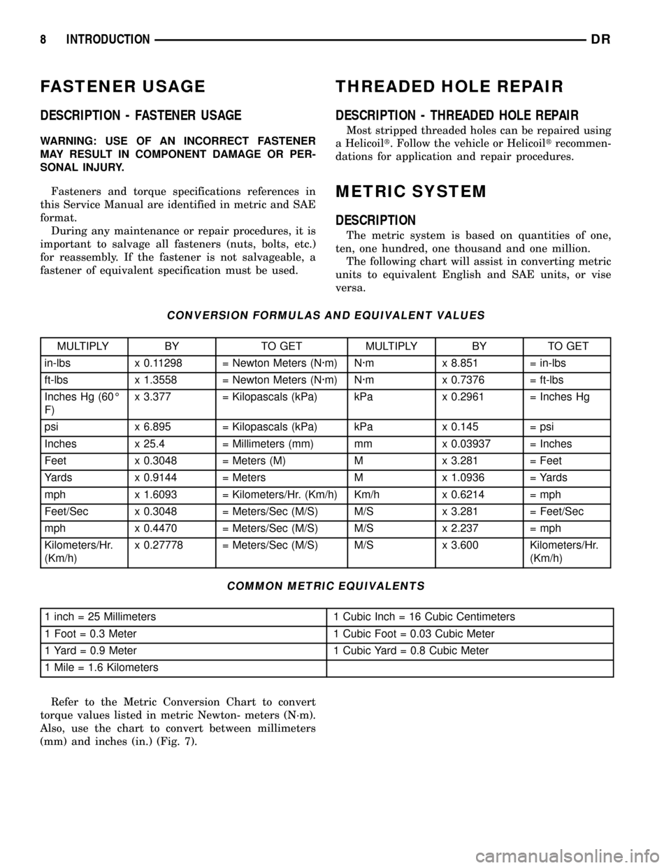
The following chart will assist in converting metric
units to equivalent English and SAE units, or vise
versa.
CONVERSION FORMULAS AND EQUIVALENT VALUES
MULTIPLY BY TO GET MULTIPLY BY TO GET
in-lbs x 0.11298 = Newton Meters (N´m) N´m x 8.851 = in-lbs
ft-lbs x 1.3558 = Newton Meters (N´m) N´m x 0.7376 = ft-lbs
Inches Hg (60É
F)x 3.377 = Kilopascals (kPa) kPa x 0.2961 = Inches Hg
psi x 6.895 = Kilopascals (kPa) kPa x 0.145 = psi
Inches x 25.4 = Millimeters (mm) mm x 0.03937 = Inches
Feet x 0.3048 = Meters (M) M x 3.281 = Feet
Yards x 0.9144 = Meters M x 1.0936 = Yards
mph x 1.6093 = Kilometers/Hr. (Km/h) Km/h x 0.6214 = mph
Feet/Sec x 0.3048 = Meters/Sec (M/S) M/S x 3.281 = Feet/Sec
mph x 0.4470 = Meters/Sec (M/S) M/S x 2.237 = mph
Kilometers/Hr.
(Km/h)x 0.27778 = Meters/Sec (M/S) M/S x 3.600 Kilometers/Hr.
(Km/h)
COMMON METRIC EQUIVALENTS
1 inch = 25 Millimeters 1 Cubic Inch = 16 Cubic Centimeters
1 Foot = 0.3 Meter 1 Cubic Foot = 0.03 Cubic Meter
1 Yard = 0.9 Meter 1 Cubic Yard = 0.8 Cubic Meter
1 Mile = 1.6 Kilometers
Refer to the Metric Conversion Chart to convert
torque values listed in metric Newton- meters (N´m).
Also, use the chart to convert between millimeters
(mm) and inches (in.) (Fig. 7).
8 INTRODUCTIONDR
Page 36 of 2627
SUSPENSION
TABLE OF CONTENTS
page page
WHEEL ALIGNMENT......................1
FRONT - INDEPENDENT FRONT SUSPENSION..8FRONT - LINK/COIL......................29
REAR.................................41
WHEEL ALIGNMENT
TABLE OF CONTENTS
page page
WHEEL ALIGNMENT
DESCRIPTION..........................1
OPERATION............................2
DIAGNOSIS AND TESTING - PRE-ALIGNMENT
INSPECTION..........................2
STANDARD PROCEDURE
STANDARD PROCEDURE - HEIGHT
MEASUREMENT - 4WD (LD)..............3
STANDARD PROCEDURE - HEIGHT
ADJUSTMENT - 4WD (LD)................3
STANDARD PROCEDURE - CAMBER AND
CASTER ADJUSTMENT..................4STANDARD PROCEDURE - TOE
ADJUSTMENT.........................4
STANDARD PROCEDURE - CAMBER,
CASTER AND TOE ADJUSTMENT..........4
STANDARD PROCEDURE - ALIGNMENT
LINK/COIL SUSPENSION.................5
SPECIFICATIONS
ALIGNMENT..........................6
SPECIAL TOOLS
WHEEL ALIGNMENT....................7
WHEEL ALIGNMENT
DESCRIPTION
NOTE: Suspension components with rubber/ure-
thane bushings should be tightened with the vehi-
cle at normal ride height. It is important to have the
springs supporting the weight of the vehicle when
the fasteners are torqued. If springs are not at their
normal ride position, vehicle ride comfort could be
affected and premature bushing wear may occur.
Wheel alignment involves the correct positioning of
the wheels in relation to the vehicle. The positioning
is accomplished through suspension and steering
linkage adjustments. An alignment is considered
essential for efficient steering, good directional stabil-
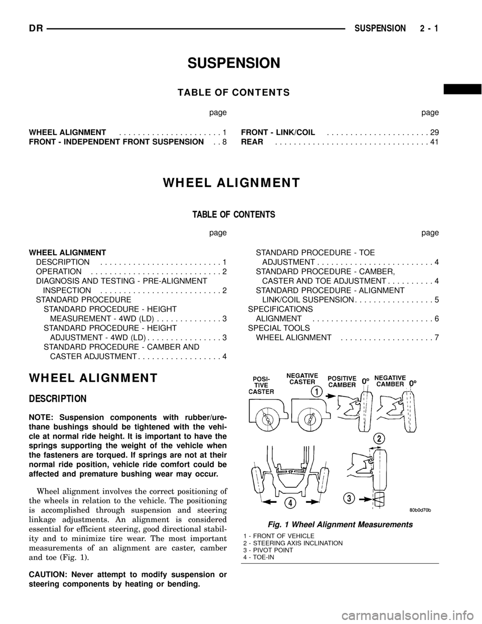
ity and to minimize tire wear. The most important
measurements of an alignment are caster, camber
and toe (Fig. 1).
CAUTION: Never attempt to modify suspension or
steering components by heating or bending.
Fig. 1 Wheel Alignment Measurements
1 - FRONT OF VEHICLE
2 - STEERING AXIS INCLINATION
3 - PIVOT POINT
4 - TOE-IN
DRSUSPENSION 2 - 1
Page 40 of 2627

angle while adjusting caster, move one pivot bolt of
the upper control arm in or out. Then move the other
pivot bolt of the upper control arm in the opposite
direction. Install special tool 8876 between the top of
the upper control arm bracket and the upper control
arm (on 1500 series 4X2 & 4X4). Install special tool
8876 between the bottom of the upper control arm
bracket pressing the tool against the frame and the
upper control arm (on 2500/3500 series 4X2) in order
to move the upper control arm outwards for proper
adjustment with the vehicle at normal ride height
(Fig. 3).
To increase positive caster angle, move the rear
position of the upper control arm inward (toward the
engine). Move the front of the upper control arm out-
ward (away from the engine) slightly until the origi-
nal camber angle is obtained using special tool 8876
to move the upper control arm for proper adjustment.
(Fig. 3)
CAMBER
Move both pivot bolts of the upper control arm
together in or out. This will change the camber angle
significantly and little effect on the caster angle
using special tool 8876 to move the upper control
arm for proper adjustment. (Fig. 3)
After adjustment is made tighten the upper control
arm nuts to proper torque specification.
TOE ADJUSTMENT
The wheel toe position adjustment is the final
adjustment.
(1) Start the engine and turn wheels both ways
before straightening the wheels. Secure the steering
wheel with the front wheels in the straight-ahead
position.
(2) Loosen the tie rod jam nuts.
NOTE: Each front wheel should be adjusted for
one-half of the total toe position specification. This
will ensure the steering wheel will be centered
when the wheels are positioned straight-ahead.
(3) Adjust the wheel toe position by turning the
inner tie rod as necessary (Fig. 4).
(4) Tighten the tie rod jam nut to 75 N´m (55 ft.
lbs.).
(5) Verify the specifications
(6) Turn off engine.
STANDARD PROCEDURE - ALIGNMENT
LINK/COIL SUSPENSION
Before each alignment reading the vehicle should
be jounced (rear first, then front). Grasp each
bumper at the center and jounce the vehicle up and
down several times. Always release the bumper inthe down position.Set the front end alignment to
specifications while the vehicle is in its NOR-
MALLY LOADED CONDITION.
CAMBER:The wheel camber angle is preset and
is not adjustable.
CASTER:Check the caster of the front axle for
correct angle. Be sure the axle is not bent or twisted.
Road test the vehicle and make left and right turn.
Observe the steering wheel return-to-center position.
Low caster will cause poor steering wheel returnabil-
ity.
Caster can be adjusted by rotating the cams on the
lower suspension arm (Fig. 5).
TOE POSITION:The wheel toe position adjust-
ment should be the final adjustment.
Fig. 4 TIE ROD END
1 - JAM NUT
2 - TIE ROD - INNER
3 - TIE ROD END - OUTER
Fig. 5 ALIGNMENT ADJUSTMENT CAM
1 - BRACKET REINFORCEMENT
2 - ADJUSTING BOLT
3 - ADJUSTMENT CAM
DRWHEEL ALIGNMENT 2 - 5
WHEEL ALIGNMENT (Continued)
Page 44 of 2627

FRONT - INDEPENDENT
FRONT SUSPENSION
DESCRIPTION
DESCRIPTION
The front suspension is designed to allow each
wheel to adapt to different road surfaces indepen-
dently. The wheels are mounted to hub/bearings
units bolted to the steering knuckle. The double-row
hub bearings are sealed and lubricated for life. The
steering knuckles turn (pivot) on ball joints.
The front suspension is comprised of (Fig. 1) (Fig.
2):
²Shock absorbers
²Torsion bar - 4X4 (LD only)
²Coil Spring - 4X2
²Control arms
²Steering knuckles
²Stabilizer bar
²Stabilizer link
²Tie Rod Ends
²Hub/Bearing
²Rack & Pinion
²Ball Joints
NOTE: Components attached with a nut must be
torqued to specification.
NOTE: Suspension components with rubber/ure-
thane bushings should be tightened with the vehi-
cle at normal ride height. It is important to have the
springs supporting the weight of the vehicle when
the fasteners are torqued. If springs are not at their
normal ride position, vehicle ride comfort could be
affected and premature bushing wear may occur.
Fig. 1 FRONT SUSPENSION - 4X2
1 - STABILIZER BAR
2 - UPPER CONTROL ARM
3 - STEERING KNUCKLE
4 - ROTOR
5 - CALIPER ADAPTER
6 - OUTER TIE ROD END
7 - STABILIZER LINK
8 - LOWER CONTROL ARM
9 - RACK & PINION
10 - COIL SPRING
11 - SHOCK ABSORBER
DRFRONT - INDEPENDENT FRONT SUSPENSION 2 - 9
Page 56 of 2627

(12) Perform a wheel alignment (Refer to 2 - SUS-
PENSION/WHEEL ALIGNMENT - STANDARD
PROCEDURE).
LOWER CONTROL ARM
REMOVAL
REMOVAL - 4X4 (LD)
(1) Raise and support the vehicle.
(2) Remove the wheel and tire assembly.
(3) Remove the upper ball joint nut. Separate ball
joint from the steering knuckle with Remover 8677.
(4) Remove the front halfshaft, (Refer to 3 - DIF-
FERENTIAL & DRIVELINE/HALF SHAFT -
REMOVAL).
(5) Remove the torsion bar, (Refer to 2 - SUSPEN-
SION/FRONT/TRACK BAR - REMOVAL).
(6) Remove the shock absorber lower bolt.
(7) Remove the stabilizer bar link (Refer to 2 -
SUSPENSION/FRONT/STABILIZER LINK -
REMOVAL).
(8) Remove the lower ball joint nut. Separate ball
joint from the steering knuckle with Remover 8677.
(9) Remove the control arm pivot bolts and suspen-
sion arm from frame rail brackets (Fig. 23).
REMOVAL - 4X2
(1) Raise and support the vehicle.
(2) Remove the tire and wheel assembly.
(3) Support the lower control arm at the outboard
side of the lower control arm to support vehicle
weight.(4) Remove the shock (Refer to 2 - SUSPENSION/
FRONT/SHOCK - REMOVAL).
(5) Install Spring Compressor DD-1278 up through
the lower suspension arm, coil spring and shock hole
in the frame. The bell-shaped adapter goes against
the lower suspension arm. Install the nut on top of
the tool at the shock hole.
(6) Tighten the spring compressor nut against bell-
shaped adapter finger tight then loosen 1/2 turn.
NOTE: This will hold the spring in place until the
lower suspension arm is separated from the steer-
ing knuckle.
(7) Remove the stabilizer link (Refer to 2 - SUS-
PENSION/FRONT/STABILIZER LINK - REMOVAL).
(8) Remove the lower ball joint nut at the steering
knuckle.
(9) Install Ball Joint Remover tool 8677 on the
lower ball joint and separate the ball joint from the
knuckle.
NOTE: Do not allow the upper control arm and
steering knuckle to rebound downwards they must
be supported.
(10) Support the upper control arm and steering
knuckle out of the way.
(11) Remove the lower control arm support.
(12) Tighten the spring compressor tool to allow
clearance for the lower ball joint to be removed out of
the knuckle.
(13) Loosen the tension on the spring compressor
tool slowly allowing the lower suspension arm to
pivot downward.
(14) Remove the spring compressor tool.
(15) Remove coil spring and isolator pad from the
vehicle (Fig. 26).
(16) Remove the front and rear pivot bolts (Fig.
24).
(17) Remove the lower control arm.
INSTALLATION
INSTALLATION - 4X4 (LD)
(1) Position the lower control arm at the frame rail
brackets. Install the pivot bolts and nuts. Tighten the
nuts finger-tight.
CAUTION: The ball joint stud taper must be CLEAN
and DRY before installing the knuckle. Clean the
stud taper with mineral spirits to remove dirt and
grease.
(2) Insert the lower ball joint into the steering
knuckle. Install and tighten the retaining nut to 52
Fig. 23 LOWER CONTROL ARM
1 - LOWER CONTROL ARM
2 - UPPER CONTROL ARM
3 - FRONT BOLT
4 - NUTS
5 - REAR BOLT
DRFRONT - INDEPENDENT FRONT SUSPENSION 2 - 21
LOWER BALL JOINT (Continued)
Page 57 of 2627

N´m (38 ft. lbs.)(on 1500 series only an additional 90É
turn is required).
(3) Install the torsion bar, (Refer to 2 - SUSPEN-
SION/FRONT/TRACK BAR - INSTALLATION).
(4) Install shock absorber lower bolt and tighten to
135 N´m (100 ft. lbs.).
(5) Install the front halfshaft, (Refer to 3 - DIF-
FERENTIAL & DRIVELINE/HALF SHAFT -
INSTALLATION).
(6) Insert the upper ball joint into the steering
knuckle. Install and tighten the retaining nut to 54
N´m (40 ft. lbs.)(on 1500 series only an additional 90É
turn is required).
(7) Install the stabilizer bar link (Refer to 2 - SUS-
PENSION/FRONT/STABILIZER LINK - INSTALLA-
TION).
(8) Tighten the lower control arm front pivot nut
to 204 N´m (150 ft. lbs.). Tighten rear pivot bolt to
204 N´m (150 ft. lbs.).
(9) Install the wheel and tire assembly,(Refer to 22
- TIRES/WHEELS/WHEELS - STANDARD PROCE-
DURE).
(10) Remove the support and lower the vehicle.
(11) Adjust the front suspension height and per-
form a wheel alignment (Refer to 2 - SUSPENSION/
WHEEL ALIGNMENT - STANDARD PROCEDURE).
INSTALLATION - 4X2
(1) Install the lower control arm into place on the
vehicle.
(2) Install the front and rear control arm pivot
bolts finger tight.
(3) Install the coil spring into the frame pocket(Re-
fer to 2 - SUSPENSION/FRONT/SPRING - INSTAL-
LATION).(4) Install the Spring Compressor DD-1278 up
through the lower suspension arm, coil spring and
shock hole in the frame.
(5) Tighten the tool nut to compress the coil
spring.
(6) Remove the support from the upper control
arm and steering knuckle.
(7) Position the lower ball joint into the steering
knuckle.
(8) Install the retaining nut on the lower ball joint
and tighten to 52 N´m (38 ft. lbs.)(on 1500 series only
an additional 90É turn is required) or 135 N´m (100
ft. lbs.)(HD 4X2 only).
(9) Support the lower control arm at the outboard
side of the lower control arm to support vehicle
weight.
(10) Remove the spring compressor tool.
(11) Install the shock absorber. (Refer to 2 - SUS-
PENSION/FRONT/SHOCK - INSTALLATION).
(12) Install the stabilizer link (Refer to 2 - SUS-
PENSION/FRONT/STABILIZER LINK - INSTALLA-
TION).
(13) Remove the lower control arm support.
(14) Install the wheel and tire assembly and lower
the vehicle. (Refer to 22 - TIRES/WHEELS/WHEELS
- STANDARD PROCEDURE).
(15) Lower the vehicle to the floor with vehicle
weight and Tighten the front and rear control arm
pivot bolts to 204 N´m (150 ft. lbs.)(LD) or 285 N´m
(210 ft. lbs.)(HD 4X2 only).
(16) Perform a wheel alignment (Refer to 2 - SUS-
PENSION/WHEEL ALIGNMENT - STANDARD
PROCEDURE).
SPRING
REMOVAL
(1) Raise and support vehicle.
(2) Remove the front wheel and tire assembly.
(3) Support the lower control arm at the outboard
side of the lower control arm to support vehicle
weight.
(4) Remove the shock absorber (Refer to 2 - SUS-
PENSION/FRONT/SHOCK - REMOVAL).
(5) Install Spring Compressor DD-1278 up through
the lower suspension arm, coil spring and shock hole
in the frame. The bell-shaped adapter goes against
the lower suspension arm. Install the nut on top of
the tool at the shock hole (Fig. 25).
(6) Tighten the spring compressor nut against bell-
shaped adapter finger tight then loosen 1/2 turn.
NOTE: This will hold the spring in place until the
lower suspension arm is separated from the steer-
ing knuckle.
Fig. 24 LOWER CONTROL ARM - 4X2
1 - FRONT PIVOT BOLT
2 - REAR PIVOT BOLT
3 - LOWER CONTROL ARM
2 - 22 FRONT - INDEPENDENT FRONT SUSPENSIONDR
LOWER CONTROL ARM (Continued)
Page 58 of 2627

(7) Remove the stabilizer link (Refer to 2 - SUS-
PENSION/FRONT/STABILIZER LINK - REMOVAL).
(8) Remove the lower ball joint nut at the steering
knuckle.
(9) Install Ball Joint Remover tool 8677 on the
lower ball joint and separate the ball joint from the
knuckle.
(10)
NOTE: Do not allow the upper control arm and
steering knuckle to rebound downwards they must
be supported.Support the upper control arm and
steering knuckle out of the way.
(11) Remove the lower control arm support.
(12) Tighten the spring compressor tool to allow
clearance for the lower ball joint to be removed out of
the knuckle.
NOTE: It may necessary to loosen the control arm
pivot bolt to allow downward swing.
(13) Loosen the tension on the spring compressor
tool slowly allowing the lower suspension arm to
pivot downward.
(14) Remove the spring compressor tool.
(15) Remove coil spring and isolator pad from the
vehicle (Fig. 26).
INSTALLATION
(1) Tape the isolator pad to the top of the coil
spring. Position the spring in the lower suspension
arm well. Be sure that the coil spring is seated in the
well.
(2) Install Spring Compressor DD-1278 up through
the lower suspension arm, coil spring and shock hole
in the frame.(3) Tighten the tool nut to compress the coil
spring.
(4) Remove the support from the upper control
arm and steering knuckle.
(5) Position the lower ball joint into the steering
knuckle.
(6) Install the retaining nut on the lower ball joint
and tighten to 52 N´m (38 ft. lbs.)(on 1500 series only
an additional 90É turn is required) or 135 N´m (100
ft. lbs.)(HD 4X2 only).
(7) Remove the spring compressor tool.
(8) Support the lower control arm at the outboard
side of the lower control arm to support vehicle
weight.
(9) Install the shock absorber. (Refer to 2 - SUS-
PENSION/FRONT/SHOCK - INSTALLATION).
(10) Install the stabilizer link (Refer to 2 - SUS-
PENSION/FRONT/STABILIZER LINK - INSTALLA-
TION).
(11) Remove the lower control arm support.
(12) Install the wheel and tire assembly and lower
the vehicle. (Refer to 22 - TIRES/WHEELS/WHEELS
- STANDARD PROCEDURE).
(13) Lower the vehicle to the floor with vehicle
weight and Tighten the front and rear control arm
pivot bolts if loosened to 204 N´m (150 ft. lbs.)(LD) or
285 N´m (210 ft. lbs.)(HD 4X2 only).
(14) Perform a wheel alignment (Refer to 2 - SUS-
PENSION/WHEEL ALIGNMENT - STANDARD
PROCEDURE).
Fig. 25 SPRING COMPRESSOR TOOL
1 - SPECIAL TOOL DD-1278
2 - BELL-SHAPED ADAPTER
Fig. 26 COIL SPRING
1 - COIL SPRING
2 - STEERING KNUCKLE
3 - OUTER TIE ROD END
4 - LOWER CONTROL ARM
5 - SHOCK
DRFRONT - INDEPENDENT FRONT SUSPENSION 2 - 23
SPRING (Continued)
Page 64 of 2627
FRONT - LINK/COIL
TABLE OF CONTENTS
page page
FRONT - LINK/COIL
SPECIFICATIONS
TORQUE CHART......................29
SPECIAL TOOLS
91/4AA ............................30
HUB / BEARING
REMOVAL.............................31
INSTALLATION.........................32
LOWER BALL JOINT
DIAGNOSIS AND TESTING - LOWER BALL
JOINT..............................34
REMOVAL.............................35
INSTALLATION.........................35
UPPER BALL JOINT
DIAGNOSIS AND TESTING - UPPER BALL
JOINT..............................36
REMOVAL.............................36
INSTALLATION.........................36
KNUCKLE
REMOVAL.............................37
INSTALLATION.........................37UPPER SUSPENSION ARM
REMOVAL
REMOVAL - LEFT.....................37
REMOVAL - RIGHT....................37
INSTALLATION
INSTALLATION - LEFT..................37
INSTALLATION - RIGHT................37
LOWER SUSPENSION ARM
REMOVAL.............................38
INSTALLATION.........................38
SHOCK
DIAGNOSIS AND TESTING - SHOCK........38
REMOVAL.............................38
INSTALLATION.........................38
SPRING
REMOVAL.............................39
INSTALLATION.........................39
STABILIZER BAR
REMOVAL.............................39
INSTALLATION.........................40
FRONT - LINK/COIL
SPECIFICATIONS
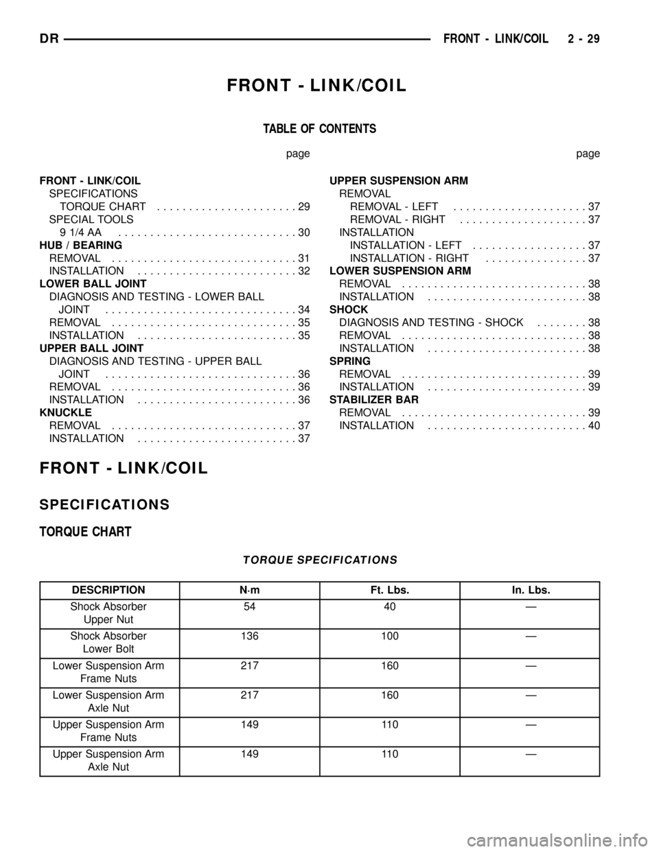
TORQUE CHART
TORQUE SPECIFICATIONS
DESCRIPTION N´m Ft. Lbs. In. Lbs.
Shock Absorber
Upper Nut54 40 Ð
Shock Absorber
Lower Bolt136 100 Ð
Lower Suspension Arm
Frame Nuts217 160 Ð
Lower Suspension Arm
Axle Nut217 160 Ð
Upper Suspension Arm
Frame Nuts149 110 Ð
Upper Suspension Arm
Axle Nut149 110 Ð
DRFRONT - LINK/COIL 2 - 29
Page 65 of 2627
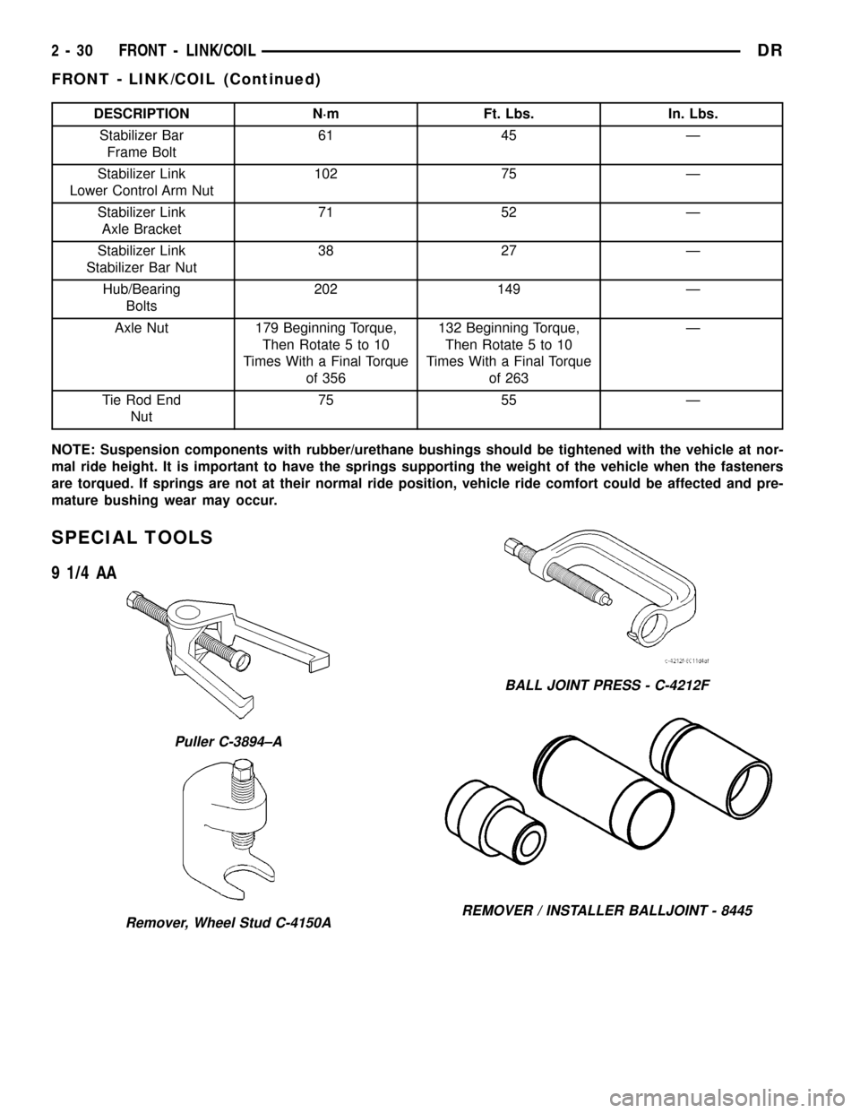
DESCRIPTION N´m Ft. Lbs. In. Lbs.
Stabilizer Bar
Frame Bolt61 45 Ð
Stabilizer Link
Lower Control Arm Nut102 75 Ð
Stabilizer Link
Axle Bracket71 52 Ð
Stabilizer Link
Stabilizer Bar Nut38 27 Ð
Hub/Bearing
Bolts202 149 Ð
Axle Nut 179 Beginning Torque,
Then Rotate 5 to 10
Times With a Final Torque
of 356132 Beginning Torque,
Then Rotate 5 to 10
Times With a Final Torque
of 263Ð
Tie Rod End
Nut75 55 Ð
NOTE: Suspension components with rubber/urethane bushings should be tightened with the vehicle at nor-
mal ride height. It is important to have the springs supporting the weight of the vehicle when the fasteners
are torqued. If springs are not at their normal ride position, vehicle ride comfort could be affected and pre-
mature bushing wear may occur.
SPECIAL TOOLS
9 1/4 AA
Puller C-3894±A
Remover, Wheel Stud C-4150A
BALL JOINT PRESS - C-4212F
REMOVER / INSTALLER BALLJOINT - 8445
2 - 30 FRONT - LINK/COILDR
FRONT - LINK/COIL (Continued)
Page 66 of 2627
HUB / BEARING
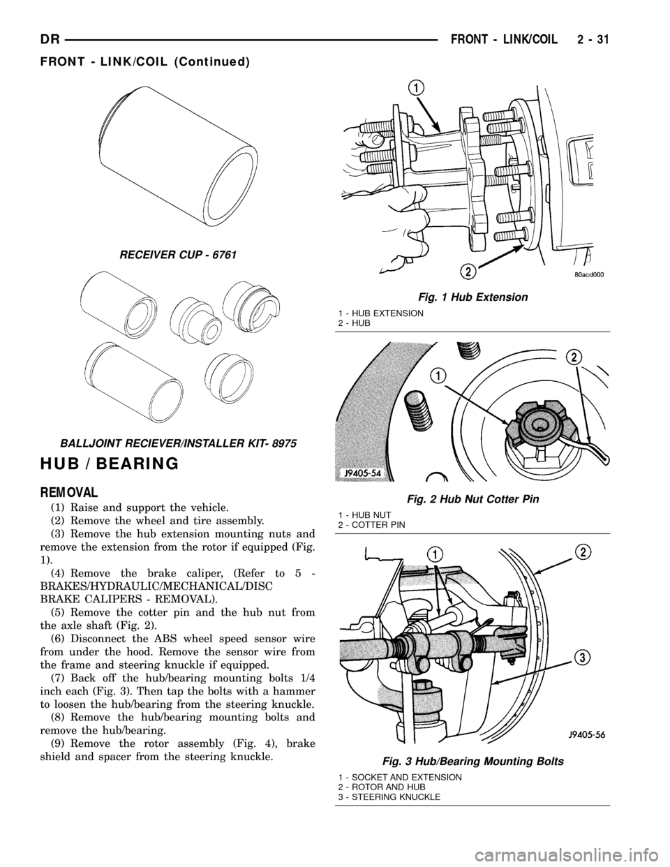
REMOVAL
(1) Raise and support the vehicle.
(2) Remove the wheel and tire assembly.
(3) Remove the hub extension mounting nuts and
remove the extension from the rotor if equipped (Fig.
1).
(4) Remove the brake caliper, (Refer to 5 -
BRAKES/HYDRAULIC/MECHANICAL/DISC
BRAKE CALIPERS - REMOVAL).
(5) Remove the cotter pin and the hub nut from
the axle shaft (Fig. 2).
(6) Disconnect the ABS wheel speed sensor wire
from under the hood. Remove the sensor wire from
the frame and steering knuckle if equipped.
(7) Back off the hub/bearing mounting bolts 1/4
inch each (Fig. 3). Then tap the bolts with a hammer
to loosen the hub/bearing from the steering knuckle.
(8) Remove the hub/bearing mounting bolts and
remove the hub/bearing.
(9) Remove the rotor assembly (Fig. 4), brake
shield and spacer from the steering knuckle.
RECEIVER CUP - 6761
BALLJOINT RECIEVER/INSTALLER KIT- 8975
Fig. 1 Hub Extension
1 - HUB EXTENSION
2 - HUB
Fig. 2 Hub Nut Cotter Pin
1 - HUB NUT
2 - COTTER PIN
Fig. 3 Hub/Bearing Mounting Bolts
1 - SOCKET AND EXTENSION
2 - ROTOR AND HUB
3 - STEERING KNUCKLE
DRFRONT - LINK/COIL 2 - 31
FRONT - LINK/COIL (Continued)