sensor DODGE RAM 2001 Service Owners Manual
[x] Cancel search | Manufacturer: DODGE, Model Year: 2001, Model line: RAM, Model: DODGE RAM 2001Pages: 2889, PDF Size: 68.07 MB
Page 647 of 2889
DIAGNOSIS & TESTING - AMBIENT
TEMPERATURE SENSOR
The thermometer function is supported by the
ambient temperature sensor, a wiring circuit, and a
portion of the compass mini-trip computer module. If
any portion of the ambient temperature sensor cir-
cuit fails, the compass/thermometer display function
will self-diagnose the circuit. If 55É C (131É F)
appears in the display, the sensor is being exposed to
temperatures above 55É C (131É F), or the sensor cir-
cuit is shorted. If ±40É C (±40É F) appears in the dis-
play, the sensor is being exposed to temperatures
below ±40É C (±40É F), or the sensor circuit is open.
The ambient temperature sensor circuit can also be
diagnosed using the following Sensor Test, and Sen-
sor Circuit Test. If the temperature sensor and cir-
cuit are confirmed to be OK, but the temperature
display is inoperative or incorrect, refer toCompass
Mini-Trip Computerin the Diagnosis and Testing
section of this group. For complete circuit diagrams,
refer toOverhead Consolein the Contents of Wir-
ing Diagrams.
SENSOR TEST
(1) Turn the ignition switch to the Off position.
Disconnect and isolate the battery negative cable.
Disconnect the ambient temperature sensor wire har-
ness connector.
(2) Measure the resistance of the ambient temper-
ature sensor. At ±40É C (±40É F), the sensor resis-
tance is 336 kilohms. At 55É C (131É F), the sensor
resistance is 2.488 kilohms. The sensor resistance
should read between these two values. If OK, refer to
Sensor Circuit Testin the Diagnosis and Testing
section of this group. If not OK, replace the faulty
ambient temperature sensor.
SENSOR CIRCUIT TEST
(1) Turn the ignition switch to the Off position.
Disconnect and isolate the battery negative cable.
Disconnect the ambient temperature sensor wire har-
ness connector and the overhead console wire har-
ness connector.
(2) Connect a jumper wire between the two termi-
nals in the body half of the ambient temperature sen-
sor wire harness connector.
(3) Check for continuity between the sensor return
circuit and the ambient temperature sensor signal
circuit cavities of the roof wire harness overhead con-
sole connector. There should be continuity. If OK, go
to Step 4. If not OK, repair the open sensor return
circuit or ambient temperature sensor signal circuit
to the ambient temperature sensor as required.(4) Remove the jumper wire from the body half of
the ambient temperature sensor wire harness con-
nector. Check for continuity between the sensor
return circuit cavity of the roof wire harness over-
head console connector and a good ground. There
should be no continuity. If OK, go to Step 5. If not
OK, repair the shorted sensor return circuit as
required.
(5) Check for continuity between the ambient tem-
perature sensor signal circuit cavity of the roof wire
harness overhead console connector and a good
ground. There should be no continuity. If OK, refer to
Compass Mini-Trip Computerin the Diagnosis
and Testing section of this group. If not OK, repair
the shorted ambient temperature sensor signal cir-
cuit as required.
REMOVAL
(1) Disconnect and isolate the battery negative
cable.
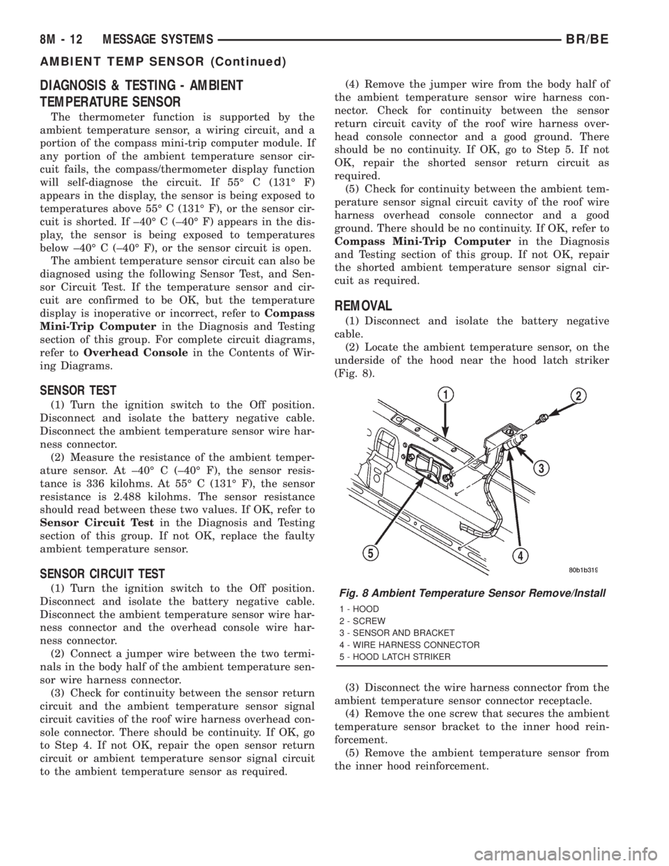
(2) Locate the ambient temperature sensor, on the
underside of the hood near the hood latch striker
(Fig. 8).
(3) Disconnect the wire harness connector from the
ambient temperature sensor connector receptacle.
(4) Remove the one screw that secures the ambient
temperature sensor bracket to the inner hood rein-
forcement.
(5) Remove the ambient temperature sensor from
the inner hood reinforcement.
Fig. 8 Ambient Temperature Sensor Remove/Install
1 - HOOD
2 - SCREW
3 - SENSOR AND BRACKET
4 - WIRE HARNESS CONNECTOR
5 - HOOD LATCH STRIKER
8M - 12 MESSAGE SYSTEMSBR/BE
AMBIENT TEMP SENSOR (Continued)
Page 648 of 2889

INSTALLATION
(1) Position the ambient temperature sensor onto
the inner hood reinforcement.
(2) Install and tighten the one screw that secures
the ambient temperature sensor bracket to the inner
hood reinforcement. Tighten the screw to 5.6 N´m (50
in. lbs.).(3) Reconnect the wire harness connector to the
ambient temperature sensor connector receptacle.
(4) Reconnect the battery negative cable.
BR/BEMESSAGE SYSTEMS 8M - 13
AMBIENT TEMP SENSOR (Continued)
Page 659 of 2889
POWER MIRRORS
TABLE OF CONTENTS
page page
POWER MIRRORS
DESCRIPTION...........................10
OPERATION.............................10
AUTOMATIC DAY / NIGHT MIRROR
DESCRIPTION...........................10
OPERATION.............................11
DIAGNOSIS AND TESTING.................11
AUTOMATIC DAY/NIGHT MIRROR..........11
REMOVAL..............................12
INSTALLATION...........................12
POWER MIRROR SWITCH
DESCRIPTION...........................12OPERATION.............................12
REMOVAL..............................12
INSTALLATION...........................13
SIDEVIEW MIRROR
DESCRIPTION...........................13
OPERATION.............................13
DIAGNOSIS AND TESTING.................13
SIDEVIEW MIRROR.....................13
REMOVAL..............................14
POWER MIRRORS
DESCRIPTION
AUTOMATIC DAY / NIGHT MIRROR
The automatic day/night mirror system is able to
automatically change the reflectance of the inside
rear view mirror in order to reduce the glare of head-
lamps approaching the vehicle from the rear. The
automatic day/night rear view mirror receives bat-
tery current through a fuse in the junction block only
when the ignition switch is in the On position.
OUTSIDE REAR VIEW MIRROR
The heated mirror option includes an electric heat-
ing grid behind the mirror glass in each outside mir-
ror, which can clear the mirror glass of ice, snow, or
fog. The heating grid receives fused battery current
through the heated mirror relay in the heater and air
conditioner control only when the ignition switch is
in the On position, and the heated mirror system is
turned on. (Refer to 8 - ELECTRICAL/HEATED
MIRRORS - DESCRIPTION) for more information.
Refer to the owner's manual in the vehicle glove
box for more information on the features, use and
operation of the power mirror system.
OPERATION
AUTOMATIC DAY / NIGHT MIRROR
A switch located on the bottom of the automatic
day/night mirror housing allows the vehicle operator
to select whether the automatic dimming feature is
operational. When the automatic day/night mirror isturned on, the mirror switch is lighted by an integral
Light-Emitting Diode (LED). The mirror will auto-
matically disable its self-dimming feature whenever
the vehicle is being driven in reverse.
Refer to the owner's manual in the vehicle glove
box for more information on the features, use and
operation of the automatic day/night mirror system.
OUTSIDE REAR VIEW MIRROR
The heated mirror option includes an electric heat-
ing grid behind the mirror glass in each outside mir-
ror, which can clear the mirror glass of ice, snow, or
fog. The heating grid receives fused battery current
through the heated mirror relay in the heater and air
conditioner control only when the ignition switch is
in the On position, and the heated mirror system is
turned on. (Refer to 8 - ELECTRICAL/HEATED
MIRRORS - OPERATION) for more information.
Refer to the owner's manual in the vehicle glove
box for more information on the features, use and
operation of the power mirror system.
AUTOMATIC DAY / NIGHT
MIRROR
DESCRIPTION
The automatic day/night mirror uses a thin layer
of electrochromic material between two pieces of con-
ductive glass to make up the face of the mirror.
When the mirror switch is in the On position, two
photocell sensors are used by the mirror circuitry to
monitor external light levels and adjust the reflec-
tance of the mirror.
8N - 10 POWER MIRRORSBR/BE
Page 660 of 2889
OPERATION
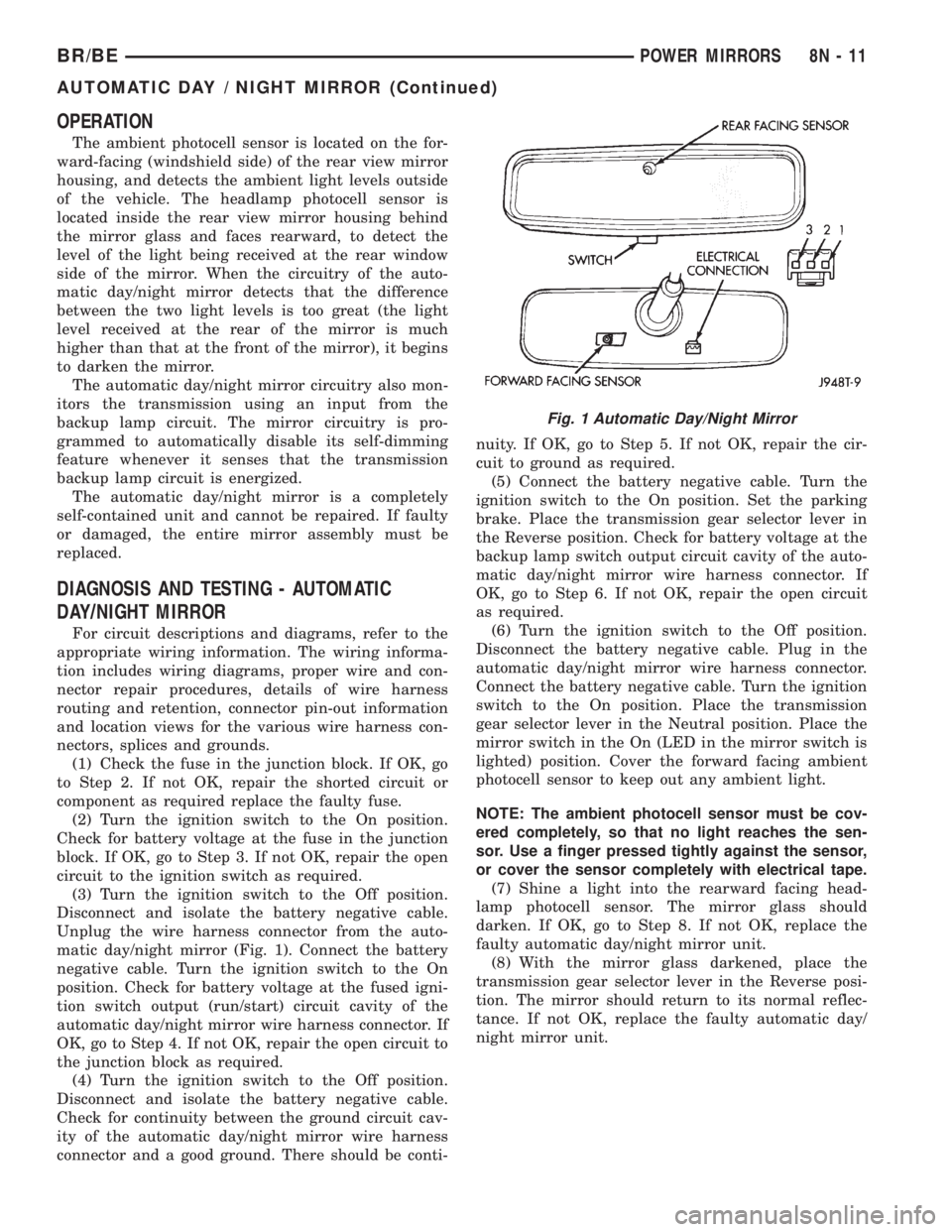
The ambient photocell sensor is located on the for-
ward-facing (windshield side) of the rear view mirror
housing, and detects the ambient light levels outside
of the vehicle. The headlamp photocell sensor is
located inside the rear view mirror housing behind
the mirror glass and faces rearward, to detect the
level of the light being received at the rear window
side of the mirror. When the circuitry of the auto-
matic day/night mirror detects that the difference
between the two light levels is too great (the light
level received at the rear of the mirror is much
higher than that at the front of the mirror), it begins
to darken the mirror.
The automatic day/night mirror circuitry also mon-
itors the transmission using an input from the
backup lamp circuit. The mirror circuitry is pro-
grammed to automatically disable its self-dimming
feature whenever it senses that the transmission
backup lamp circuit is energized.
The automatic day/night mirror is a completely
self-contained unit and cannot be repaired. If faulty
or damaged, the entire mirror assembly must be
replaced.
DIAGNOSIS AND TESTING - AUTOMATIC
DAY/NIGHT MIRROR
For circuit descriptions and diagrams, refer to the
appropriate wiring information. The wiring informa-
tion includes wiring diagrams, proper wire and con-
nector repair procedures, details of wire harness
routing and retention, connector pin-out information
and location views for the various wire harness con-
nectors, splices and grounds.
(1) Check the fuse in the junction block. If OK, go
to Step 2. If not OK, repair the shorted circuit or
component as required replace the faulty fuse.
(2) Turn the ignition switch to the On position.
Check for battery voltage at the fuse in the junction
block. If OK, go to Step 3. If not OK, repair the open
circuit to the ignition switch as required.
(3) Turn the ignition switch to the Off position.
Disconnect and isolate the battery negative cable.
Unplug the wire harness connector from the auto-
matic day/night mirror (Fig. 1). Connect the battery
negative cable. Turn the ignition switch to the On
position. Check for battery voltage at the fused igni-
tion switch output (run/start) circuit cavity of the
automatic day/night mirror wire harness connector. If
OK, go to Step 4. If not OK, repair the open circuit to
the junction block as required.
(4) Turn the ignition switch to the Off position.
Disconnect and isolate the battery negative cable.
Check for continuity between the ground circuit cav-
ity of the automatic day/night mirror wire harness
connector and a good ground. There should be conti-nuity. If OK, go to Step 5. If not OK, repair the cir-
cuit to ground as required.
(5) Connect the battery negative cable. Turn the
ignition switch to the On position. Set the parking
brake. Place the transmission gear selector lever in
the Reverse position. Check for battery voltage at the
backup lamp switch output circuit cavity of the auto-
matic day/night mirror wire harness connector. If
OK, go to Step 6. If not OK, repair the open circuit
as required.
(6) Turn the ignition switch to the Off position.
Disconnect the battery negative cable. Plug in the
automatic day/night mirror wire harness connector.
Connect the battery negative cable. Turn the ignition
switch to the On position. Place the transmission
gear selector lever in the Neutral position. Place the
mirror switch in the On (LED in the mirror switch is
lighted) position. Cover the forward facing ambient
photocell sensor to keep out any ambient light.
NOTE: The ambient photocell sensor must be cov-
ered completely, so that no light reaches the sen-
sor. Use a finger pressed tightly against the sensor,
or cover the sensor completely with electrical tape.
(7) Shine a light into the rearward facing head-
lamp photocell sensor. The mirror glass should
darken. If OK, go to Step 8. If not OK, replace the
faulty automatic day/night mirror unit.
(8) With the mirror glass darkened, place the
transmission gear selector lever in the Reverse posi-
tion. The mirror should return to its normal reflec-
tance. If not OK, replace the faulty automatic day/
night mirror unit.
Fig. 1 Automatic Day/Night Mirror
BR/BEPOWER MIRRORS 8N - 11
AUTOMATIC DAY / NIGHT MIRROR (Continued)
Page 678 of 2889
Deployment of the airbags depends upon the angle
and severity of the impact. The airbag system is
designed to deploy upon a frontal impact within a
thirty degree angle from either side of the vehicle
center line. Deployment is not based upon vehicle
speed; rather, deployment is based upon the rate of
deceleration as measured by the forces of gravity (G
force) upon the airbag system impact sensor, which is
integral to the ACM. When a frontal impact is severe
enough, the microprocessor in the ACM signals the
inflator units of both airbag modules to deploy the
airbags. During a frontal vehicle impact, the knee
blockers work in concert with properly fastened and
adjusted seat belts to restrain both the driver and
the front seat passenger in the proper position for an
airbag deployment. The knee blockers also absorb
and distribute the crash energy from the driver and
the front seat passenger to the structure of the
instrument panel.
Typically, the driver and front seat passenger recall
more about the events preceding and following a col-
lision than they have of the airbag deployment itself.
This is because the airbag deployment and deflation
occur so rapidly. In a typical 48 kilometer-per-hour
(30 mile-per-hour) barrier impact, from the moment
of impact until both airbags are fully inflated takes
about 40 milliseconds. Within one to two seconds
from the moment of impact, both airbags are almost
entirely deflated. The times cited for these events are
approximations, which apply only to a barrier impact
at the given speed. Actual times will vary somewhat,
depending upon the vehicle speed, impact angle,
severity of the impact, and the type of collision.
When the ACM monitors a problem in any of the
airbag system circuits or components, it stores a
fault code or Diagnostic Trouble Code (DTC) in its
memory circuit and sends an electronic message to
the EMIC to turn on the airbag indicator. Proper
testing of the airbag system components, the
Chrysler Collision Detection (CCD) data bus, the
data bus message inputs to and outputs from the
EMIC or the ACM, as well as the retrieval or erasure
of a DTC from the ACM requires the use of a
DRBIIItscan tool. Refer to the appropriate diagnos-
tic information.
See the owner's manual in the vehicle glove box for
more information on the features, use and operation
of all of the factory-installed passenger restraints,
including the airbag system.
WARNING
WARNING: THE AIRBAG SYSTEM IS A SENSITIVE,
COMPLEX ELECTROMECHANICAL UNIT. BEFORE
ATTEMPTING TO DIAGNOSE OR SERVICE ANY AIR-
BAG SYSTEM OR RELATED STEERING WHEEL,STEERING COLUMN, OR INSTRUMENT PANEL
COMPONENTS YOU MUST FIRST DISCONNECT
AND ISOLATE THE BATTERY NEGATIVE (GROUND)
CABLE. THEN WAIT TWO MINUTES FOR THE SYS-
TEM CAPACITOR TO DISCHARGE BEFORE FUR-
THER SYSTEM SERVICE. THIS IS THE ONLY SURE
WAY TO DISABLE THE AIRBAG SYSTEM. FAILURE
TO DO THIS COULD RESULT IN ACCIDENTAL AIR-
BAG DEPLOYMENT AND POSSIBLE PERSONAL
INJURY.
WARNING: THE DRIVER AIRBAG INFLATOR UNIT
CONTAINS SODIUM AZIDE AND POTASSIUM
NITRATE. THESE MATERIALS ARE POISONOUS
AND EXTREMELY FLAMMABLE. CONTACT WITH
ACID, WATER, OR HEAVY METALS MAY PRODUCE
HARMFUL AND IRRITATING GASES (SODIUM
HYDROXIDE IS FORMED IN THE PRESENCE OF
MOISTURE) OR COMBUSTIBLE COMPOUNDS. THE
PASSENGER AIRBAG UNIT CONTAINS ARGON GAS
PRESSURIZED TO OVER 2500 PSI. DO NOT
ATTEMPT TO DISMANTLE AN AIRBAG UNIT OR
TAMPER WITH ITS INFLATOR. DO NOT PUNCTURE,
INCINERATE, OR BRING INTO CONTACT WITH
ELECTRICITY. DO NOT STORE AT TEMPERATURES
EXCEEDING 93É C (200É F).
WARNING: REPLACE AIRBAG SYSTEM COMPO-
NENTS ONLY WITH PARTS SPECIFIED IN THE
DAIMLERCHRYSLER MOPAR PARTS CATALOG.
SUBSTITUTE PARTS MAY APPEAR INTERCHANGE-
ABLE, BUT INTERNAL DIFFERENCES MAY RESULT
IN INFERIOR OCCUPANT PROTECTION.
WARNING: THE FASTENERS, SCREWS, AND
BOLTS ORIGINALLY USED FOR THE AIRBAG SYS-
TEM COMPONENTS HAVE SPECIAL COATINGS
AND ARE SPECIFICALLY DESIGNED FOR THE AIR-
BAG SYSTEM. THEY MUST NEVER BE REPLACED
WITH ANY SUBSTITUTES. ANY TIME A NEW FAS-
TENER IS NEEDED, REPLACE IT WITH THE COR-
RECT FASTENERS PROVIDED IN THE SERVICE
PACKAGE OR SPECIFIED IN THE DAIMLER-
CHRYSLER MOPAR PARTS CATALOG.
WARNING: WHEN A STEERING COLUMN HAS AN
AIRBAG UNIT ATTACHED, NEVER PLACE THE COL-
UMN ON THE FLOOR OR ANY OTHER SURFACE
WITH THE STEERING WHEEL OR AIRBAG UNIT
FACE DOWN.
BR/BERESTRAINTS 8O - 3
RESTRAINTS (Continued)
Page 681 of 2889
(9) Turn the ignition switch to the Off position for
about fifteen seconds, and then back to the On posi-
tion. Observe the airbag indicator in the instrument
cluster. It should light for six to eight seconds, and
then go out. This indicates that the airbag system is
functioning normally and that the repairs are com-
plete. If the airbag indicator fails to light, or lights
and stays on, there is still an active airbag system
fault or malfunction. Refer to the appropriate diag-
nostic information to diagnose the problem.
SPECIAL TOOLS
SPECIAL TOOLS - AIRBAG SYSTEM
AIRBAG CONTROL MODULE
DESCRIPTION
The Airbag Control Module (ACM) is concealed
underneath the plastic ACM trim cover (automatic
transmission) or center console (manual transmis-
sion), directly below the instrument panel in the pas-
senger compartment of the vehicle. The ACM is
secured with screws to a mounting bracket located
under the instrument panel center support bracket
on the floor panel transmission tunnel. The ACM
contains an electronic microprocessor, an electronic
impact sensor, an electromechanical safing sensor,
and an energy storage capacitor. The ACM is con-
nected to the vehicle electrical system through a take
out and connector of the instrument panel wire har-
ness.
The ACM cannot be repaired or adjusted and, if
damaged or faulty, it must be replaced.
OPERATION
The microprocessor in the ACM contains the airbag
system logic circuits, and it monitors and controls all
of the airbag system components. The ACM also uses
On-Board Diagnostics (OBD) and can communicate
with other electronic modules in the vehicle as well
as with the DRBIIItscan tool using the Chrysler
Collision Detection (CCD) data bus network. This
method of communication is used for control of the
airbag indicator in the ElectroMechanical InstrumentCluster (EMIC) and for airbag system diagnosis and
testing through the 16-way data link connector
located on the lower left edge of the instrument
panel. (Refer to 8 - ELECTRICAL/ELECTRONIC
CONTROL MODULES/COMMUNICATION - OPER-
ATION). The ACM microprocessor continuously mon-
itors all of the airbag system electrical circuits to
determine the system readiness. If the ACM detects
a monitored system fault, it sets an active Diagnostic
Trouble Code (DTC) and sends messages to the
EMIC over the CCD data bus to turn on the airbag
indicator. (Refer to 8 - ELECTRICAL/INSTRUMENT
CLUSTER/AIRBAG INDICATOR - OPERATION). If
the airbag system fault is still present when the igni-
tion switch is turned to the Off position, the DTC is
stored in memory by the ACM. However, if a fault
does not recur for a number of ignition cycles, the
ACM will automatically erase the stored DTC.
The ACM receives battery current through two cir-
cuits, on a fused ignition switch output (run) circuit
through a fuse in the Junction Block (JB), and on a
fused ignition switch output (start-run) circuit
through a second fuse in the JB. The ACM is
grounded through a ground circuit and take out of
the instrument panel wire harness. This take out has
a single eyelet terminal connector secured by a nut to
a ground stud located on the forward extension of the
left front fender wheel housing in the engine com-
partment. Therefore, the ACM is operational when-
ever the ignition switch is in the Start or On
positions. The ACM also contains an energy-storage
capacitor. When the ignition switch is in the Start or
On positions, this capacitor is continually being
charged with enough electrical energy to deploy the
airbags for up to one second following a battery dis-
connect or failure. The purpose of the capacitor is to
provide backup airbag system protection in case
there is a loss of battery current supply to the ACM
during an impact. The capacitor is only serviced as a
unit with the ACM.
Two sensors are contained within the ACM, an
electronic impact sensor and a safing sensor. The
electronic impact sensor is an accelerometer that
senses the rate of vehicle deceleration, which pro-
vides verification of the direction and severity of an
impact. A pre-programmed decision algorithm in the
ACM microprocessor determines when the decelera-
tion rate as signaled by the impact sensor indicates
an impact that is severe enough to require airbag
system protection. When the programmed conditions
are met, the ACM sends an electrical signal to deploy
the airbags. The safing sensor is an electromechani-
cal sensor within the ACM that is connected in series
between the ACM microprocessor airbag deployment
circuit and the airbags. The safing sensor is a nor-
mally open switch that is used to verify or confirm
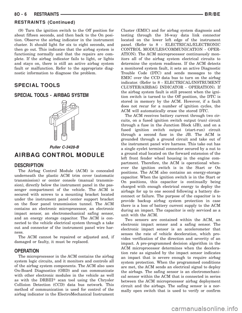
Puller C-3428-B
8O - 6 RESTRAINTSBR/BE
RESTRAINTS (Continued)
Page 682 of 2889
the need for an airbag deployment by detecting
impact energy of a lesser magnitude than that of the
electronic impact sensor, and must be closed in order
for the airbags to deploy. The impact sensor and saf-
ing sensor are calibrated for the specific vehicle, and
are only serviced as a unit with the ACM.
REMOVAL
WARNING: DISABLE THE AIRBAG SYSTEM
BEFORE ATTEMPTING ANY STEERING WHEEL,
STEERING COLUMN, OR INSTRUMENT PANEL
COMPONENT DIAGNOSIS OR SERVICE. DISCON-
NECT AND ISOLATE THE BATTERY NEGATIVE
(GROUND) CABLE, THEN WAIT TWO MINUTES FOR
THE AIRBAG SYSTEM CAPACITOR TO DISCHARGE
BEFORE PERFORMING FURTHER DIAGNOSIS OR
SERVICE. THIS IS THE ONLY SURE WAY TO DIS-
ABLE THE AIRBAG SYSTEM. FAILURE TO TAKE
THE PROPER PRECAUTIONS COULD RESULT IN
ACCIDENTAL AIRBAG DEPLOYMENT AND POSSI-
BLE PERSONAL INJURY.
WARNING: THE AIRBAG CONTROL MODULE CON-
TAINS THE IMPACT SENSOR, WHICH ENABLES
THE SYSTEM TO DEPLOY THE AIRBAGS. NEVER
STRIKE OR KICK THE AIRBAG CONTROL MODULE,
AS IT CAN DAMAGE THE IMPACT SENSOR OR
AFFECT ITS CALIBRATION. IF AN AIRBAG CON-
TROL MODULE IS ACCIDENTALLY DROPPED DUR-
ING SERVICE, THE MODULE MUST BE SCRAPPED
AND REPLACED WITH A NEW UNIT. FAILURE TO
OBSERVE THIS WARNING COULD RESULT IN ACCI-
DENTAL, INCOMPLETE, OR IMPROPER AIRBAG
DEPLOYMENT AND POSSIBLE OCCUPANT INJU-
RIES.
(1) Disconnect and isolate the battery negative
cable. If either of the airbags has not been deployed,
wait two minutes for the system capacitor to dis-
charge before further service.
(2) If the vehicle is equipped with a manual trans-
mission, remove the center floor console from the
floor panel transmission tunnel. (Refer to 23 - BODY/
INTERIOR/CENTER CONSOLE - REMOVAL).
(3) If the vehicle is equipped with an automatic
transmission, remove the two screws that secure the
trim cover to the Airbag Control Module (ACM)
mounting bracket on the floor panel transmission
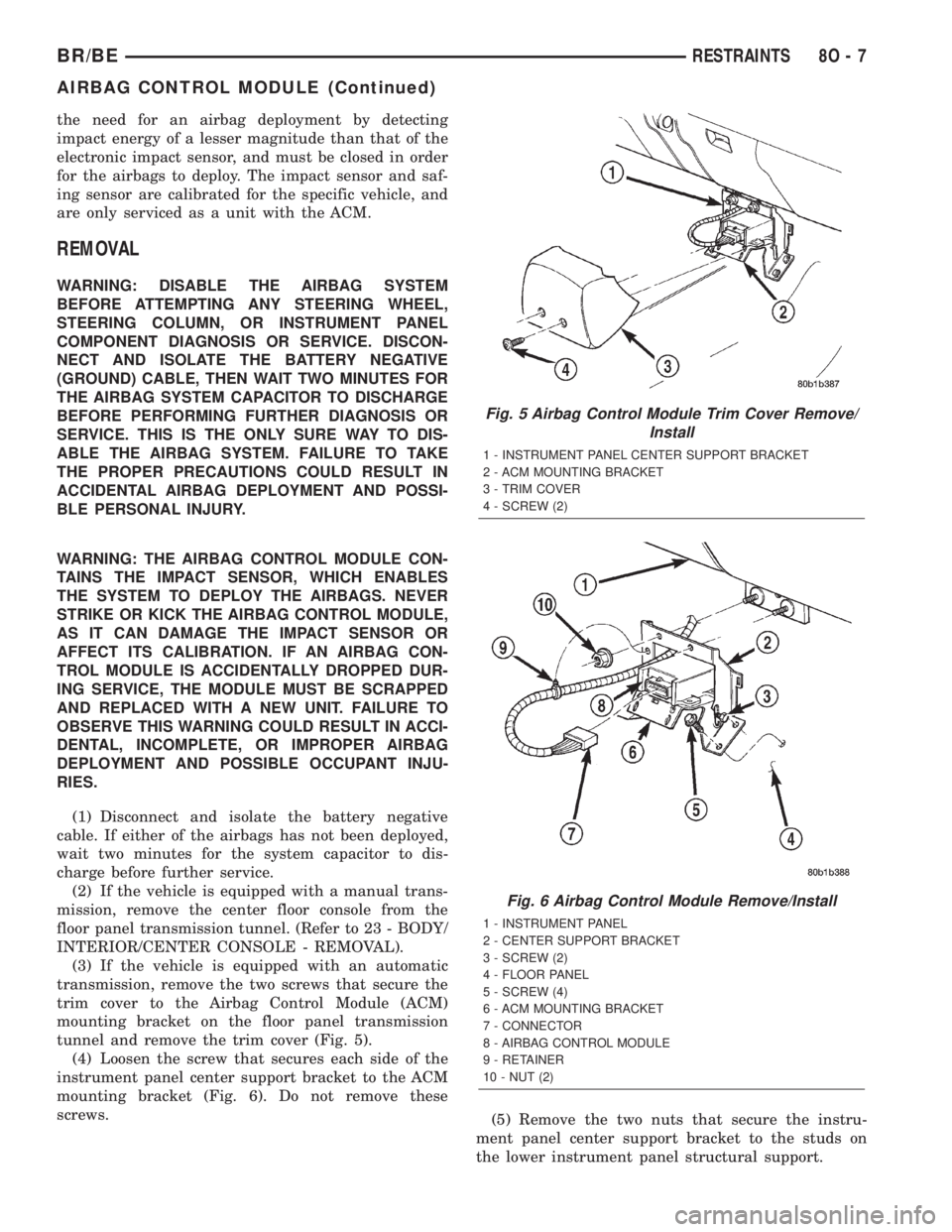
tunnel and remove the trim cover (Fig. 5).
(4) Loosen the screw that secures each side of the
instrument panel center support bracket to the ACM
mounting bracket (Fig. 6). Do not remove these
screws.
(5) Remove the two nuts that secure the instru-
ment panel center support bracket to the studs on
the lower instrument panel structural support.
Fig. 5 Airbag Control Module Trim Cover Remove/
Install
1 - INSTRUMENT PANEL CENTER SUPPORT BRACKET
2 - ACM MOUNTING BRACKET
3 - TRIM COVER
4 - SCREW (2)
Fig. 6 Airbag Control Module Remove/Install
1 - INSTRUMENT PANEL
2 - CENTER SUPPORT BRACKET
3 - SCREW (2)
4 - FLOOR PANEL
5 - SCREW (4)
6 - ACM MOUNTING BRACKET
7 - CONNECTOR
8 - AIRBAG CONTROL MODULE
9 - RETAINER
10 - NUT (2)
BR/BERESTRAINTS 8O - 7
AIRBAG CONTROL MODULE (Continued)
Page 683 of 2889
(6) Disengage the retainer on the instrument
panel wire harness take out to the ACM from the
retainer hole in the left side of the instrument panel
center support bracket.
(7) Pull the top of the instrument panel center
support bracket rearward and down from the instru-
ment panel studs. Fold it down over the top of the
ACM until it is laying flat on the floor panel trans-
mission tunnel.
(8) Disconnect the instrument panel wire harness
connector for the ACM from the ACM connector
receptacle. To disconnect this connector:
(a) Slide the red Connector Position Assurance
(CPA) lock on the top of the connector toward the
side of the vehicle.
(b) Depress the connector latch tab and pull the
connector straight away from the ACM connector
receptacle.
NOTE: Always remove and replace the ACM and its
mounting bracket as a unit. Replacement modules
include a replacement mounting bracket. Do not
transfer the ACM to another mounting bracket.
(9) Remove the four screws that secure the ACM
mounting bracket to the floor panel transmission
tunnel.
(10) Remove the ACM, the mounting bracket, and
the instrument panel center support bracket from the
floor panel transmission tunnel as a unit.
INSTALLATION
WARNING: DISABLE THE AIRBAG SYSTEM
BEFORE ATTEMPTING ANY STEERING WHEEL,
STEERING COLUMN, OR INSTRUMENT PANEL
COMPONENT DIAGNOSIS OR SERVICE. DISCON-
NECT AND ISOLATE THE BATTERY NEGATIVE
(GROUND) CABLE, THEN WAIT TWO MINUTES FOR
THE AIRBAG SYSTEM CAPACITOR TO DISCHARGE
BEFORE PERFORMING FURTHER DIAGNOSIS OR
SERVICE. THIS IS THE ONLY SURE WAY TO DIS-
ABLE THE AIRBAG SYSTEM. FAILURE TO TAKE
THE PROPER PRECAUTIONS COULD RESULT IN
ACCIDENTAL AIRBAG DEPLOYMENT AND POSSI-
BLE PERSONAL INJURY.
WARNING: THE AIRBAG CONTROL MODULE CON-
TAINS THE IMPACT SENSOR, WHICH ENABLES
THE SYSTEM TO DEPLOY THE AIRBAGS. NEVER
STRIKE OR KICK THE AIRBAG CONTROL MODULE,
AS IT CAN DAMAGE THE IMPACT SENSOR OR
AFFECT ITS CALIBRATION. IF AN AIRBAG CON-
TROL MODULE IS ACCIDENTALLY DROPPED DUR-
ING SERVICE, THE MODULE MUST BE SCRAPPED
AND REPLACED WITH A NEW UNIT. FAILURE TOOBSERVE THIS WARNING COULD RESULT IN ACCI-
DENTAL, INCOMPLETE, OR IMPROPER AIRBAG
DEPLOYMENT AND POSSIBLE OCCUPANT INJU-
RIES.
(1) Carefully position the Airbag Control Module
(ACM), the mounting bracket, and the instrument
panel center support bracket onto the floor panel
transmission tunnel as a unit (Fig. 6). When the
ACM is correctly positioned, the arrow on the ACM
label will be pointed forward in the vehicle.
(2) Install and tighten the four screws that secure
the ACM mounting bracket to the floor panel trans-
mission tunnel. Tighten the screws to 14 N´m (125
in. lbs.).
(3) With the instrument panel center support
bracket still folded down flat on the floor panel trans-
mission tunnel, reconnect the instrument panel wire
harness connector for the ACM to the ACM connector
receptacle. Be certain that the connector latch and
the red Connector Position Assurance (CPA) lock are
fully engaged.
(4) Fold the top of the instrument panel center
support bracket up over the top of the ACM and for-
ward over the studs on the lower instrument panel
structural support.
(5) Install and tighten the nuts that secure the
instrument panel center support bracket to the studs
on the lower instrument panel structural support.
Tighten the nuts to 14 N´m (125 in. lbs.).
(6) Engage the retainer on the instrument panel
wire harness take out for the ACM in the retainer
hole on the left side of the instrument panel center
support bracket.
(7) Tighten the screws that secure each side of the
instrument panel center support bracket to the ACM
mounting bracket. Tighten the screws 14 N´m (125
in. lbs.).
(8) If the vehicle is equipped with an automatic
transmission, position the ACM trim cover to the
ACM mounting bracket on the floor panel transmis-
sion tunnel (Fig. 5).
(9) If the vehicle is equipped with an automatic
transmission, install and tighten the two screws that
secure the ACM trim cover to the ACM mounting
bracket. Tighten the screws to 2.2 N´m (20 in. lbs.).
(10) If the vehicle is equipped with a manual
transmission, reinstall the center floor console onto
the floor panel transmission tunnel. (Refer to 23 -
BODY/INTERIOR/CENTER CONSOLE - INSTALLA-
TION).
(11) Do not reconnect the battery negative cable at
this time. The airbag system verification test proce-
dure should be performed following service of any
airbag system component. (Refer to 8 - ELECTRI-
CAL/RESTRAINTS - STANDARD PROCEDURE -
VERIFICATION TEST).
8O - 8 RESTRAINTSBR/BE
AIRBAG CONTROL MODULE (Continued)
Page 706 of 2889
SPEED CONTROL
TABLE OF CONTENTS
page page
SPEED CONTROL
DESCRIPTION............................1
OPERATION.............................2
DIAGNOSIS AND TESTING..................2
VACUUM SUPPLY.......................2
ROAD TEST............................3
SPECIFICATIONS.........................4
CABLE
DESCRIPTION............................4
OPERATION.............................4
REMOVAL...............................4
INSTALLATION............................4
SPEED CONTROL SERVO
DESCRIPTION............................5OPERATION.............................5
REMOVAL...............................6
INSTALLATION...........................10
SWITCH
DESCRIPTION...........................12
OPERATION.............................12
REMOVAL..............................13
INSTALLATION...........................13
VACUUM RESERVOIR
DESCRIPTION...........................13
REMOVAL..............................13
INSTALLATION...........................14
SPEED CONTROL
DESCRIPTION - SPEED CONTROL SYSTEM
Gas Engines and/or Diesel With Automatic Trans.
The speed control system is operated by the use of
a cable and a vacuum controlled servo. Electronic
control of the speed control system is integrated into
the Powertrain Control Module (PCM). The controls
consist of two steering wheel mounted switches. The
switches are labeled: ON/OFF, RES/ACCEL, SET,
COAST, and CANCEL.
The system is designed to operate at speeds above
30 mph (50 km/h).
WARNING: THE USE OF SPEED CONTROL IS NOT
RECOMMENDED WHEN DRIVING CONDITIONS DO
NOT PERMIT MAINTAINING A CONSTANT SPEED,
SUCH AS IN HEAVY TRAFFIC OR ON ROADS THAT
ARE WINDING, ICY, SNOW COVERED, OR SLIP-
PERY.
Diesel With Manual Trans.
The speed control system is fully electronically con-
trolled by the Engine Control Module (ECM).A
cable and a vacuum controlled servo are not
used if the vehicle is equipped with a manual
transmission and a diesel engine. This is a ser-
vo-less system.The controls consist of two steering
wheel mounted switches. The switches are labeled:
ON/OFF, RES/ACCEL, SET, COAST, and CANCEL.
The system is designed to operate at speeds above
30 mph (50 km/h).WARNING: THE USE OF SPEED CONTROL IS NOT
RECOMMENDED WHEN DRIVING CONDITIONS DO
NOT PERMIT MAINTAINING A CONSTANT SPEED,
SUCH AS IN HEAVY TRAFFIC OR ON ROADS THAT
ARE WINDING, ICY, SNOW COVERED, OR SLIP-
PERY.
DESCRIPTION - VEHICLE SPEED INPUT
Gas Engines and/or Diesel With Automatic Trans.
The Vehicle Speed Sensor (VSS) is no longer used
for any Dodge Truck.
Vehicle speed and distance covered are measured by
the Rear Wheel Speed Sensor. The sensor is mounted
to the rear axle. A signal is sent from this sensor to the
Controller Antilock Brake (CAB) computer. A signal is
then sent from the CAB to the Powertrain Control
Module (PCM) to determine vehicle speed and distance
covered. The PCM will then determine strategies for
speed control system operation.
Diesel With Manual Trans.
The Vehicle Speed Sensor (VSS) is no longer used
for any Dodge Truck.
Vehicle speed and distance covered are measured
by the Rear Wheel Speed Sensor. The sensor is
mounted to the rear axle. A signal is sent from this
sensor to the Controller Antilock Brake (CAB) com-
puter. A signal is then sent from the CAB to the
Engine Control Module (ECM) to determine vehicle
speed and distance covered. The ECM will then
determine strategies for speed control system opera-
tion.
BR/BESPEED CONTROL 8P - 1
Page 756 of 2889
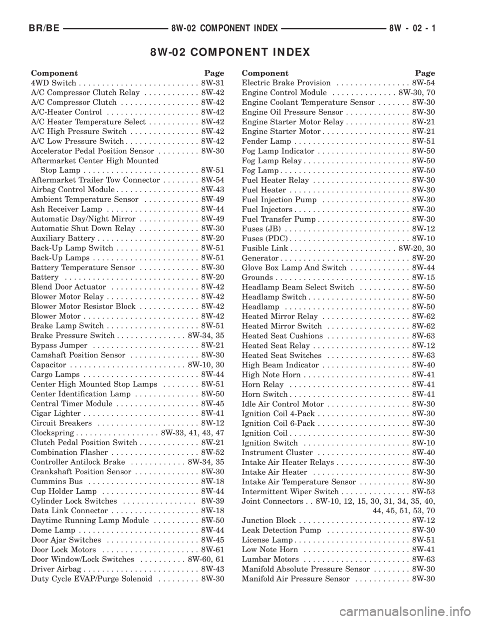
8W-02 COMPONENT INDEX
Component Page
4WD Switch.......................... 8W-31
A/C Compressor Clutch Relay............ 8W-42
A/C Compressor Clutch................. 8W-42
A/C-Heater Control.................... 8W-42
A/C Heater Temperature Select........... 8W-42
A/C High Pressure Switch............... 8W-42
A/C Low Pressure Switch................ 8W-42
Accelerator Pedal Position Sensor......... 8W-30
Aftermarket Center High Mounted
Stop Lamp......................... 8W-51
Aftermarket Trailer Tow Connector........ 8W-54
Airbag Control Module.................. 8W-43
Ambient Temperature Sensor............ 8W-49
Ash Receiver Lamp.................... 8W-44
Automatic Day/Night Mirror............. 8W-49
Automatic Shut Down Relay............. 8W-30
Auxiliary Battery...................... 8W-20
Back-Up Lamp Switch.................. 8W-51
Back-Up Lamps....................... 8W-51
Battery Temperature Sensor............. 8W-30
Battery............................. 8W-20
Blend Door Actuator................... 8W-42
Blower Motor Relay.................... 8W-42
Blower Motor Resistor Block............. 8W-42
Blower Motor......................... 8W-42
Brake Lamp Switch.................... 8W-51
Brake Pressure Switch............... 8W-34, 35
Bypass Jumper....................... 8W-21
Camshaft Position Sensor............... 8W-30
Capacitor......................... 8W-10, 30
Cargo Lamps......................... 8W-44
Center High Mounted Stop Lamps........ 8W-51
Center Identification Lamp.............. 8W-50
Central Timer Module.................. 8W-45
Cigar Lighter......................... 8W-41
Circuit Breakers...................... 8W-12
Clockspring.................. 8W-33, 41, 43, 47
Clutch Pedal Position Switch............. 8W-21
Combination Flasher................... 8W-52
Controller Antilock Brake............ 8W-34, 35
Crankshaft Position Sensor.............. 8W-30
Cummins Bus........................ 8W-18
Cup Holder Lamp..................... 8W-44
Cylinder Lock Switches................ 8W-39
Data Link Connector................... 8W-18
Daytime Running Lamp Module.......... 8W-50
Dome Lamp.......................... 8W-44
Door Ajar Switches.................... 8W-45
Door Lock Motors..................... 8W-61
Door Window/Lock Switches.......... 8W-60, 61
Driver Airbag......................... 8W-43
Duty Cycle EVAP/Purge Solenoid......... 8W-30Component Page
Electric Brake Provision................ 8W-54
Engine Control Module.............. 8W-30, 70
Engine Coolant Temperature Sensor....... 8W-30
Engine Oil Pressure Sensor.............. 8W-30
Engine Starter Motor Relay.............. 8W-21
Engine Starter Motor................... 8W-21
Fender Lamp......................... 8W-51
Fog Lamp Indicator.................... 8W-50
Fog Lamp Relay....................... 8W-50
Fog Lamp............................ 8W-50
Fuel Heater Relay..................... 8W-30
Fuel Heater.......................... 8W-30
Fuel Injection Pump................... 8W-30
Fuel Injectors......................... 8W-30
Fuel Transfer Pump.................... 8W-30
Fuses (JB)........................... 8W-12
Fuses (PDC).......................... 8W-10
Fusible Link....................... 8W-20, 30
Generator............................ 8W-20
Glove Box Lamp And Switch............. 8W-44
Grounds............................. 8W-15
Headlamp Beam Select Switch........... 8W-50
Headlamp Switch...................... 8W-50
Headlamp........................... 8W-50
Heated Mirror Relay................... 8W-62
Heated Mirror Switch.................. 8W-62
Heated Seat Cushions.................. 8W-63
Heated Seat Relay..................... 8W-12
Heated Seat Switches.................. 8W-63
High Beam Indicator................... 8W-40
High Note Horn....................... 8W-41
Horn Relay.......................... 8W-41
Horn Switch.......................... 8W-41
Idle Air Control Motor.................. 8W-30
Ignition Coil 4-Pack.................... 8W-30
Ignition Coil 6-Pack.................... 8W-30
Ignition Coil.......................... 8W-30
Ignition Switch....................... 8W-10
Instrument Cluster.................... 8W-40
Intake Air Heater Relays................ 8W-30
Intake Air Heater..................... 8W-30
Intake Air Temperature Sensor........... 8W-30
Intermittent Wiper Switch............... 8W-53
Joint Connectors . . 8W-10, 12, 15, 30, 31, 34, 35, 40,
44, 45, 51, 53, 70
Junction Block........................ 8W-12
Leak Detection Pump.................. 8W-30
License Lamp......................... 8W-51
Low Note Horn....................... 8W-41
Lumbar Motors....................... 8W-63
Manifold Absolute Pressure Sensor........ 8W-30
Manifold Air Pressure Sensor............ 8W-30
BR/BE8W-02 COMPONENT INDEX 8W - 02 - 1