DODGE RAM 2001 Service Repair Manual
Manufacturer: DODGE, Model Year: 2001, Model line: RAM, Model: DODGE RAM 2001Pages: 2889, PDF Size: 68.07 MB
Page 1691 of 2889
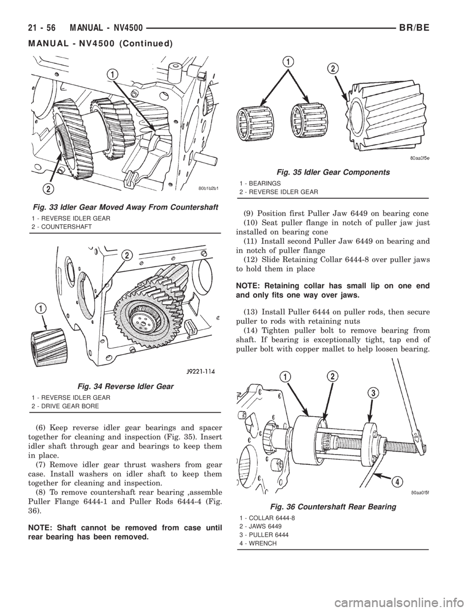
(6) Keep reverse idler gear bearings and spacer
together for cleaning and inspection (Fig. 35). Insert
idler shaft through gear and bearings to keep them
in place.
(7) Remove idler gear thrust washers from gear
case. Install washers on idler shaft to keep them
together for cleaning and inspection.
(8) To remove countershaft rear bearing ,assemble
Puller Flange 6444-1 and Puller Rods 6444-4 (Fig.
36).
NOTE: Shaft cannot be removed from case until
rear bearing has been removed.(9) Position first Puller Jaw 6449 on bearing cone
(10) Seat puller flange in notch of puller jaw just
installed on bearing cone
(11) Install second Puller Jaw 6449 on bearing and
in notch of puller flange
(12) Slide Retaining Collar 6444-8 over puller jaws
to hold them in place
NOTE: Retaining collar has small lip on one end
and only fits one way over jaws.
(13) Install Puller 6444 on puller rods, then secure
puller to rods with retaining nuts
(14) Tighten puller bolt to remove bearing from
shaft. If bearing is exceptionally tight, tap end of
puller bolt with copper mallet to help loosen bearing.
Fig. 33 Idler Gear Moved Away From Countershaft
1 - REVERSE IDLER GEAR
2 - COUNTERSHAFT
Fig. 34 Reverse Idler Gear
1 - REVERSE IDLER GEAR
2 - DRIVE GEAR BORE
Fig. 35 Idler Gear Components
1 - BEARINGS
2 - REVERSE IDLER GEAR
Fig. 36 Countershaft Rear Bearing
1 - COLLAR 6444-8
2 - JAWS 6449
3 - PULLER 6444
4 - WRENCH
21 - 56 MANUAL - NV4500BR/BE
MANUAL - NV4500 (Continued)
Page 1692 of 2889
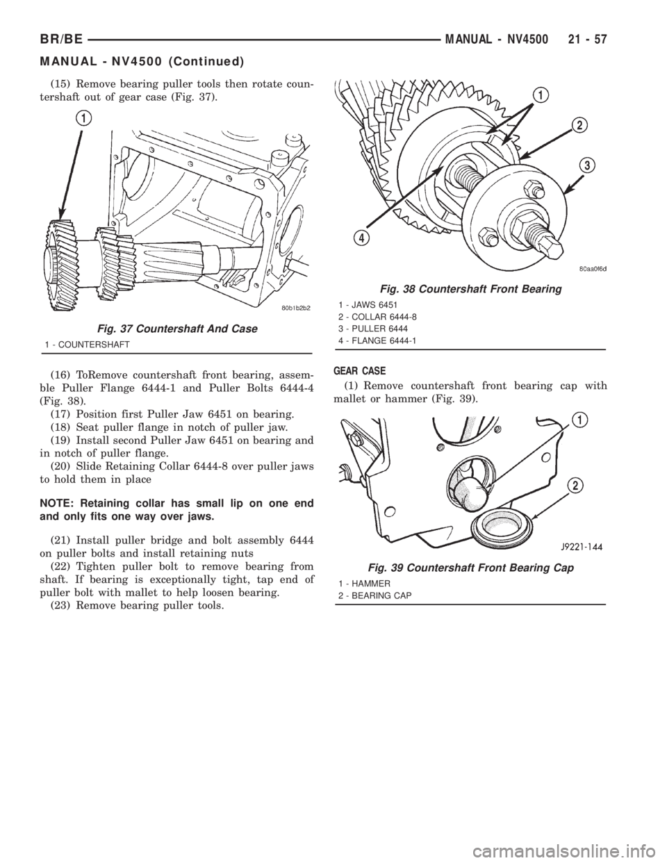
(15) Remove bearing puller tools then rotate coun-
tershaft out of gear case (Fig. 37).
(16) ToRemove countershaft front bearing, assem-
ble Puller Flange 6444-1 and Puller Bolts 6444-4
(Fig. 38).
(17) Position first Puller Jaw 6451 on bearing.
(18) Seat puller flange in notch of puller jaw.
(19) Install second Puller Jaw 6451 on bearing and
in notch of puller flange.
(20) Slide Retaining Collar 6444-8 over puller jaws
to hold them in place
NOTE: Retaining collar has small lip on one end
and only fits one way over jaws.
(21) Install puller bridge and bolt assembly 6444
on puller bolts and install retaining nuts
(22) Tighten puller bolt to remove bearing from
shaft. If bearing is exceptionally tight, tap end of
puller bolt with mallet to help loosen bearing.
(23) Remove bearing puller tools.GEAR CASE
(1) Remove countershaft front bearing cap with
mallet or hammer (Fig. 39).
Fig. 37 Countershaft And Case
1 - COUNTERSHAFT
Fig. 38 Countershaft Front Bearing
1 - JAWS 6451
2 - COLLAR 6444-8
3 - PULLER 6444
4 - FLANGE 6444-1
Fig. 39 Countershaft Front Bearing Cap
1 - HAMMER
2 - BEARING CAP
BR/BEMANUAL - NV4500 21 - 57
MANUAL - NV4500 (Continued)
Page 1693 of 2889
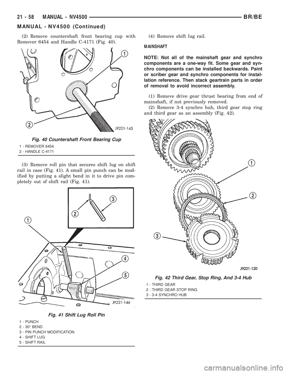
(2) Remove countershaft front bearing cup with
Remover 6454 and Handle C-4171 (Fig. 40).
(3) Remove roll pin that secures shift lug on shift
rail in case (Fig. 41). A small pin punch can be mod-
ified by putting a slight bend in it to drive pin com-
pletely out of shift rail (Fig. 41).(4) Remove shift lug rail.
MAINSHAFT
NOTE: Not all of the mainshaft gear and synchro
components are a one-way fit. Some gear and syn-
chro components can be installed backwards. Paint
or scriber gear and synchro components for instal-
lation reference. Then stack geartrain parts in order
of removal to avoid incorrect assembly.
(1) Remove drive gear thrust bearing from end of
mainshaft, if not previously removed.
(2) Remove 3-4 synchro hub, third gear stop ring
and third gear as an assembly (Fig. 42).
Fig. 40 Countershaft Front Bearing Cup
1 - REMOVER 6454
2 - HANDLE C-4171
Fig. 41 Shift Lug Roll Pin
1 - PUNCH
2 - 30É BEND
3 - PIN PUNCH MODIFICATION
4 - SHIFT LUG
5 - SHIFT RAIL
Fig. 42 Third Gear, Stop Ring, And 3-4 Hub
1 - THIRD GEAR
2 - THIRD GEAR STOP RING
3 - 3-4 SYNCHRO HUB
21 - 58 MANUAL - NV4500BR/BE
MANUAL - NV4500 (Continued)
Page 1694 of 2889
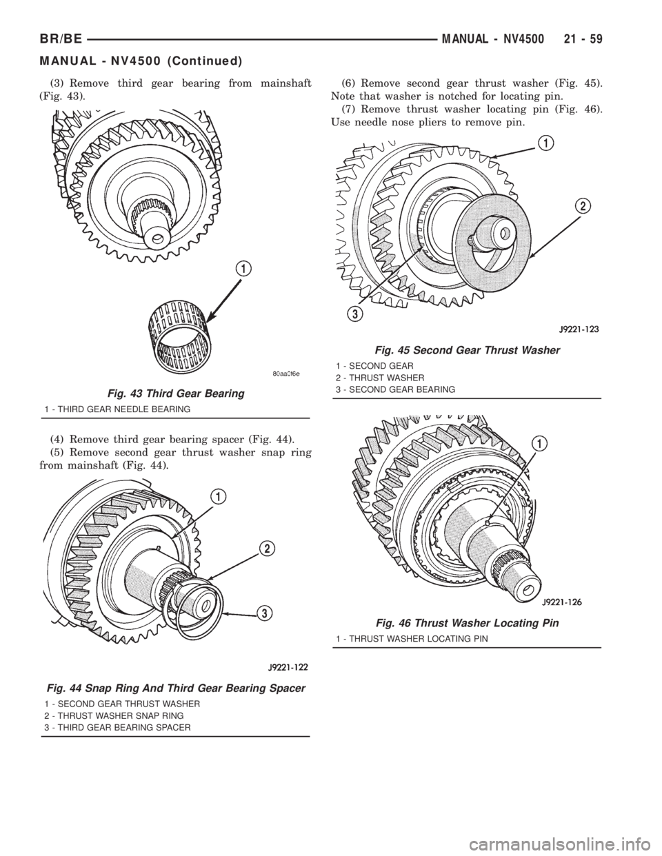
(3) Remove third gear bearing from mainshaft
(Fig. 43).
(4) Remove third gear bearing spacer (Fig. 44).
(5) Remove second gear thrust washer snap ring
from mainshaft (Fig. 44).(6) Remove second gear thrust washer (Fig. 45).
Note that washer is notched for locating pin.
(7) Remove thrust washer locating pin (Fig. 46).
Use needle nose pliers to remove pin.
Fig. 43 Third Gear Bearing
1 - THIRD GEAR NEEDLE BEARING
Fig. 44 Snap Ring And Third Gear Bearing Spacer
1 - SECOND GEAR THRUST WASHER
2 - THRUST WASHER SNAP RING
3 - THIRD GEAR BEARING SPACER
Fig. 45 Second Gear Thrust Washer
1 - SECOND GEAR
2 - THRUST WASHER
3 - SECOND GEAR BEARING
Fig. 46 Thrust Washer Locating Pin
1 - THRUST WASHER LOCATING PIN
BR/BEMANUAL - NV4500 21 - 59
MANUAL - NV4500 (Continued)
Page 1695 of 2889
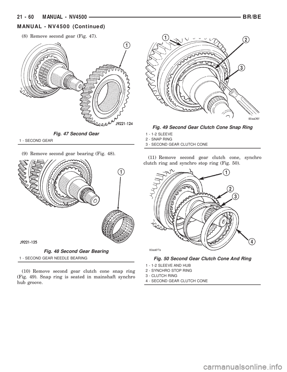
(8) Remove second gear (Fig. 47).
(9) Remove second gear bearing (Fig. 48).
(10) Remove second gear clutch cone snap ring
(Fig. 49). Snap ring is seated in mainshaft synchro
hub groove.(11) Remove second gear clutch cone, synchro
clutch ring and synchro stop ring (Fig. 50).
Fig. 47 Second Gear
1 - SECOND GEAR
Fig. 48 Second Gear Bearing
1 - SECOND GEAR NEEDLE BEARING
Fig. 49 Second Gear Clutch Cone Snap Ring
1 - 1-2 SLEEVE
2 - SNAP RING
3 - SECOND GEAR CLUTCH CONE
Fig. 50 Second Gear Clutch Cone And Ring
1 - 1-2 SLEEVE AND HUB
2 - SYNCHRO STOP RING
3 - CLUTCH RING
4 - SECOND GEAR CLUTCH CONE
21 - 60 MANUAL - NV4500BR/BE
MANUAL - NV4500 (Continued)
Page 1696 of 2889
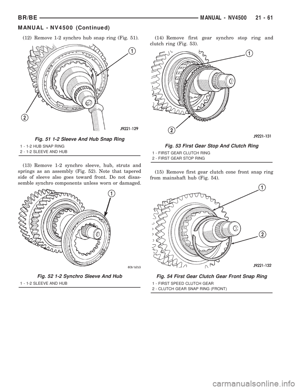
(12) Remove 1-2 synchro hub snap ring (Fig. 51).
(13) Remove 1-2 synchro sleeve, hub, struts and
springs as an assembly (Fig. 52). Note that tapered
side of sleeve also goes toward front. Do not disas-
semble synchro components unless worn or damaged.(14) Remove first gear synchro stop ring and
clutch ring (Fig. 53).
(15) Remove first gear clutch cone front snap ring
from mainshaft hub (Fig. 54).
Fig. 51 1-2 Sleeve And Hub Snap Ring
1 - 1-2 HUB SNAP RING
2 - 1-2 SLEEVE AND HUB
Fig. 52 1-2 Synchro Sleeve And Hub
1 - 1-2 SLEEVE AND HUB
Fig. 53 First Gear Stop And Clutch Ring
1 - FIRST GEAR CLUTCH RING
2 - FIRST GEAR STOP RING
Fig. 54 First Gear Clutch Gear Front Snap Ring
1 - FIRST SPEED CLUTCH GEAR
2 - CLUTCH GEAR SNAP RING (FRONT)
BR/BEMANUAL - NV4500 21 - 61
MANUAL - NV4500 (Continued)
Page 1697 of 2889
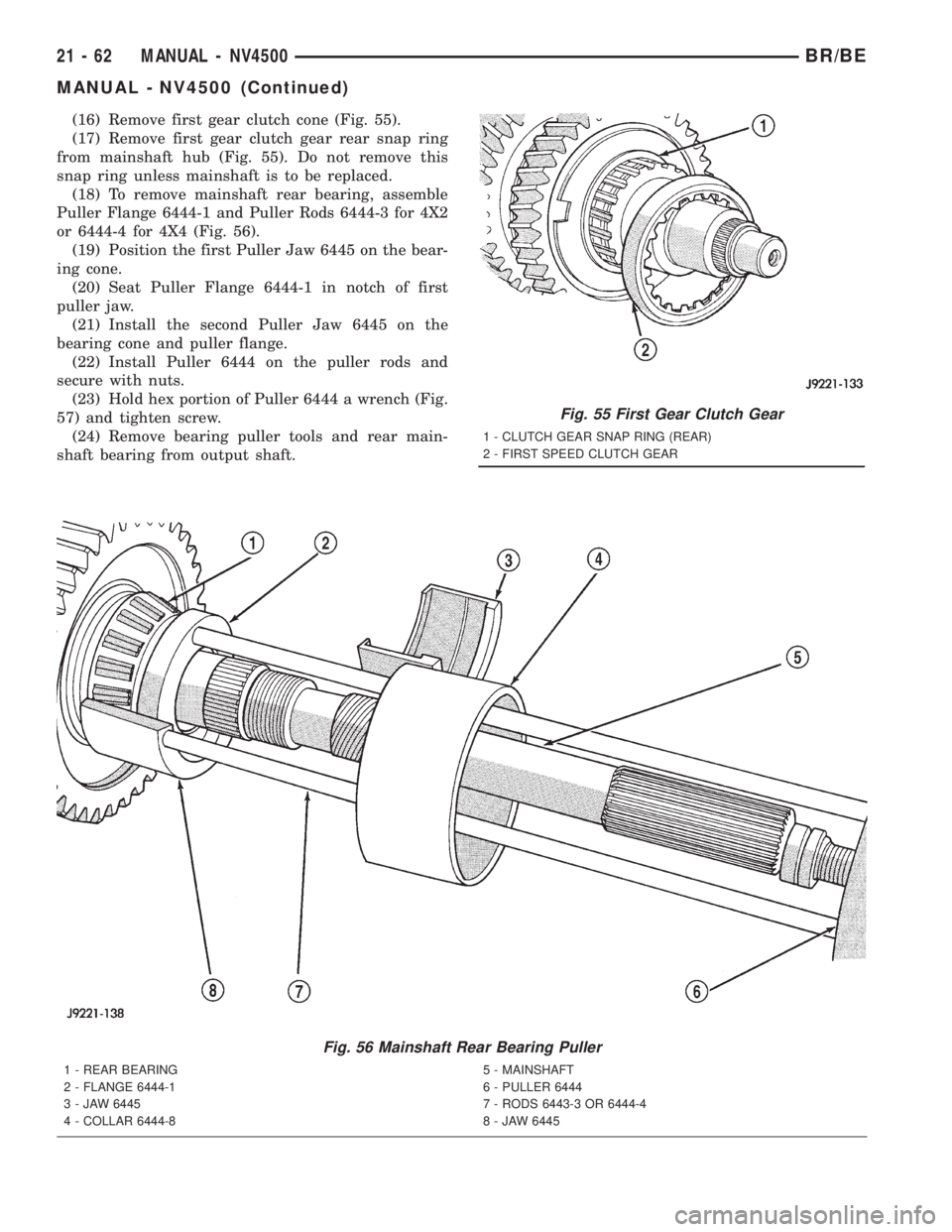
(16) Remove first gear clutch cone (Fig. 55).
(17) Remove first gear clutch gear rear snap ring
from mainshaft hub (Fig. 55). Do not remove this
snap ring unless mainshaft is to be replaced.
(18) To remove mainshaft rear bearing, assemble
Puller Flange 6444-1 and Puller Rods 6444-3 for 4X2
or 6444-4 for 4X4 (Fig. 56).
(19) Position the first Puller Jaw 6445 on the bear-
ing cone.
(20) Seat Puller Flange 6444-1 in notch of first
puller jaw.
(21) Install the second Puller Jaw 6445 on the
bearing cone and puller flange.
(22) Install Puller 6444 on the puller rods and
secure with nuts.
(23) Hold hex portion of Puller 6444 a wrench (Fig.
57) and tighten screw.
(24) Remove bearing puller tools and rear main-
shaft bearing from output shaft.
Fig. 56 Mainshaft Rear Bearing Puller
1 - REAR BEARING
2 - FLANGE 6444-1
3 - JAW 6445
4 - COLLAR 6444-85 - MAINSHAFT
6 - PULLER 6444
7 - RODS 6443-3 OR 6444-4
8 - JAW 6445
Fig. 55 First Gear Clutch Gear
1 - CLUTCH GEAR SNAP RING (REAR)
2 - FIRST SPEED CLUTCH GEAR
21 - 62 MANUAL - NV4500BR/BE
MANUAL - NV4500 (Continued)
Page 1698 of 2889
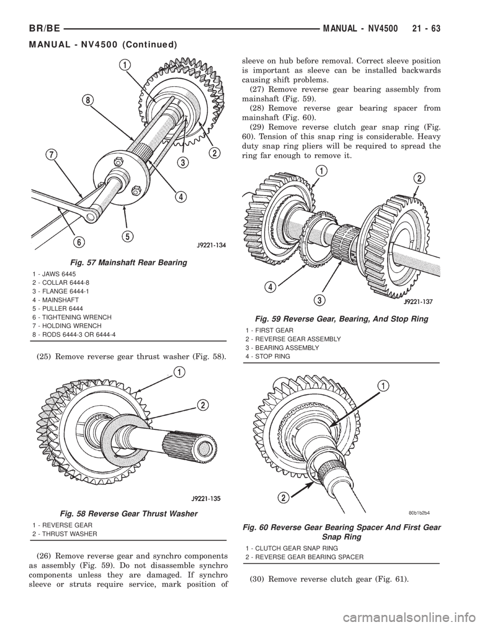
(25) Remove reverse gear thrust washer (Fig. 58).
(26) Remove reverse gear and synchro components
as assembly (Fig. 59). Do not disassemble synchro
components unless they are damaged. If synchro
sleeve or struts require service, mark position ofsleeve on hub before removal. Correct sleeve position
is important as sleeve can be installed backwards
causing shift problems.
(27) Remove reverse gear bearing assembly from
mainshaft (Fig. 59).
(28) Remove reverse gear bearing spacer from
mainshaft (Fig. 60).
(29) Remove reverse clutch gear snap ring (Fig.
60). Tension of this snap ring is considerable. Heavy
duty snap ring pliers will be required to spread the
ring far enough to remove it.
(30) Remove reverse clutch gear (Fig. 61).
Fig. 57 Mainshaft Rear Bearing
1 - JAWS 6445
2 - COLLAR 6444-8
3 - FLANGE 6444-1
4 - MAINSHAFT
5 - PULLER 6444
6 - TIGHTENING WRENCH
7 - HOLDING WRENCH
8 - RODS 6444-3 OR 6444-4
Fig. 58 Reverse Gear Thrust Washer
1 - REVERSE GEAR
2 - THRUST WASHER
Fig. 59 Reverse Gear, Bearing, And Stop Ring
1 - FIRST GEAR
2 - REVERSE GEAR ASSEMBLY
3 - BEARING ASSEMBLY
4 - STOP RING
Fig. 60 Reverse Gear Bearing Spacer And First Gear
Snap Ring
1 - CLUTCH GEAR SNAP RING
2 - REVERSE GEAR BEARING SPACER
BR/BEMANUAL - NV4500 21 - 63
MANUAL - NV4500 (Continued)
Page 1699 of 2889
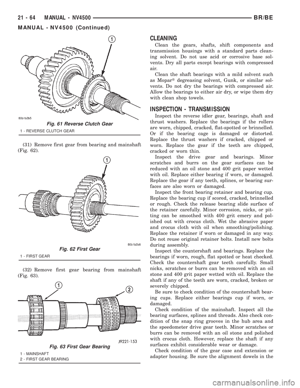
(31) Remove first gear from bearing and mainshaft
(Fig. 62).
(32) Remove first gear bearing from mainshaft
(Fig. 63).
CLEANING
Clean the gears, shafts, shift components and
transmission housings with a standard parts clean-
ing solvent. Do not use acid or corrosive base sol-
vents. Dry all parts except bearings with compressed
air.
Clean the shaft bearings with a mild solvent such
as Mopartdegreasing solvent, Gunk, or similar sol-
vents. Do not dry the bearings with compressed air.
Allow the bearings to either air dry, or wipe them dry
with clean shop towels.
INSPECTION - TRANSMISSION
Inspect the reverse idler gear, bearings, shaft and
thrust washers. Replace the bearings if the rollers
are worn, chipped, cracked, flat-spotted or brinnelled.
Or if the bearing cage is damaged or distorted.
Replace the thrust washers if cracked, chipped or
worn. Replace the gear if the teeth are chipped,
cracked or worn thin.
Inspect the drive gear and bearings. Minor
scratches and burrs on the gear surfaces can be
reduced with an oil stone and 400 grit paper wetted
with oil. Replace either bearing if worn, or damaged.
Replace the gear if any teeth, splines, or bearing sur-
faces are also worn or damaged.
Inspect the front bearing retainer and bearing cup.
Replace the bearing cup if scored, cracked, brinnelled
or rough. Check the release bearing slide surface of
the retainer carefully. Minor corrosion, nicks, or pit-
ting can be smoothed with 400 grit emery and pol-
ished out with crocus cloth. Wet the abrasive paper
and crocus cloth with oil when smoothing/polishing.
Replace the retainer if worn or damaged in any way.
Do not reuse original retainer bolts. Install new bolts
during assembly.
Inspect the countershaft and bearings. Replace the
bearings if worn, rough, flat spotted or heat checked.
Check the countershaft gear teeth carefully. Small
nicks, scratches or burrs can be removed with an oil
stone and 400 grit paper wetted with oil. Replace the
shaft if any of the teeth are worn, cracked, broken or
severely chipped.
Be sure to check condition of the countershaft bear-
ing cups. Replace either bearings cup if worn, or
damaged.
Check condition of the mainshaft. Inspect all the
bearing surfaces, splines and threads. Also check con-
dition of the snap ring grooves in the hub area and
the speedometer drive gear teeth. Minor scratches or
burrs can be removed with an oil stone and polished
with crocus cloth. However, replace the shaft if any
surfaces exhibit considerable wear or damage.
Check condition of the gear case and extension or
adapter housing. Be sure the alignment dowels in the
Fig. 61 Reverse Clutch Gear
1 - REVERSE CLUTCH GEAR
Fig. 62 First Gear
1 - FIRST GEAR
Fig. 63 First Gear Bearing
1 - MAINSHAFT
2 - FIRST GEAR BEARING
21 - 64 MANUAL - NV4500BR/BE
MANUAL - NV4500 (Continued)
Page 1700 of 2889
case top surface and in the housing/adapter are tight
and in good condition.
Run a tap through the gear case bolt holes if the
threads need minor cleanup. Helicoil inserts can be
used to repair seriously damaged threaded holes if
necessary.
Be sure all case and housing/adapter sealing and
mating surfaces are free of burrs and nicks. This is
especially important as gaskets are not used in the
transmission. Minor nicks and scratches on the seal-
ing surfaces can be dressed off with a fine tooth file
or oil stone.
Replace the gear case or housing/adapter if cracked
or broken. Do not attempt to repair this type of dam-
age by welding or brazing.
Check condition of the countershaft fifth gear com-
ponents. This includes the shift lug and rail located
in the gear case and the rail bushings.
Inspect the gear and hub assembly. Minor burrs
can be cleaned up with an oil stone. However, the
gear and hub assembly should be replaced if the
teeth or splines are excessively worn, or damaged.
The synchro sleeve should also be replaced if worn or
damaged in any way. Do not reuse synchro struts
that are worn or springs that are collapsed or
severely distorted. Replace worn distorted synchro
parts to avoid shift problems after assembly and
installation.
The shift fork should be inspected for evidence of
wear and distortion. Check fit of the sleeve in the
fork to be sure the two parts fit and work smoothly.
Replace the fork if the roll pin holes are worn over-
size or damaged. Do not attempt to salvage a worn
fork. It will cause shift problems later on. Replace
shift fork roll pins if necessary or if doubt exists
about their condition.
The bearings should be examined carefully for
wear, roughness, flat spots, pitting or other damage.
Replace the bearings if necessary.
Inspect the blocker ring and clutch gear. replace
either part if worn or damaged in any way. Also be
sure replacement parts fit properly before proceeding
with assembly.
Examine the 1-2 synchro hub and sleeve for wear
or damage. Replace sleeve and hub if the splines are
worn, chipped or damaged.
Replace the synchro struts if worn, or chipped. Also
replace the springs if collapsed, distorted or broken.
Inspect the mainshaft geartrain components.
Check teeth on all gears, hubs, clutch gears, stop
rings and clutch rings. The teeth must be in good
condition and not worn, cracked or chipped. Replace
any component that exhibits wear or damage.
Examine the synchro stop rings, clutch rings and
clutch gears. Replace any part that exhibits wear,distortion or damage. Replace the clutch rings if the
friction material is burned, flaking off or worn.
Inspect all of the thrust washers and locating pins.
Replace the pins if bent or worn. Replace the wash-
ers if worn or the locating pin notches are distorted.
Check condition of the synchro struts and springs.
Replace these parts if worn, cracked or distorted.
ASSEMBLY
NOTE: Gaskets are not used in the NV4500 trans-
mission. Use MoparTSilicone Sealer or equivalent
on all gear case and extension housing sealing sur-
faces.
COUNTERSHAFT AND REVERSE IDLER GEAR
(1) Install countershaft front bearing cup in case
with Handle C-4171 and Installer 6061-1.
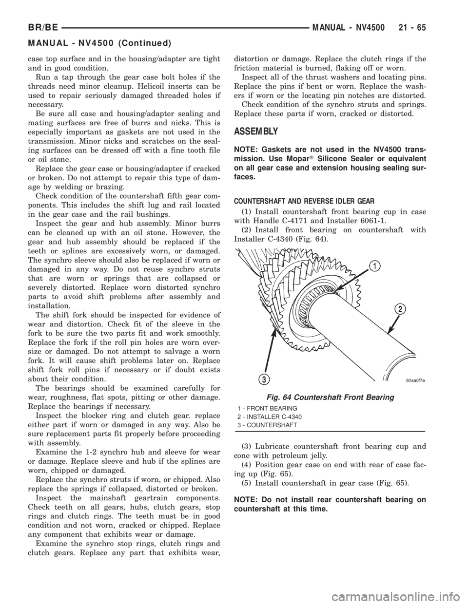
(2) Install front bearing on countershaft with
Installer C-4340 (Fig. 64).
(3) Lubricate countershaft front bearing cup and
cone with petroleum jelly.
(4) Position gear case on end with rear of case fac-
ing up (Fig. 65).
(5) Install countershaft in gear case (Fig. 65).
NOTE: Do not install rear countershaft bearing on
countershaft at this time.
Fig. 64 Countershaft Front Bearing
1 - FRONT BEARING
2 - INSTALLER C-4340
3 - COUNTERSHAFT
BR/BEMANUAL - NV4500 21 - 65
MANUAL - NV4500 (Continued)