DODGE RAM 2001 Service Repair Manual
Manufacturer: DODGE, Model Year: 2001, Model line: RAM, Model: DODGE RAM 2001Pages: 2889, PDF Size: 68.07 MB
Page 1731 of 2889
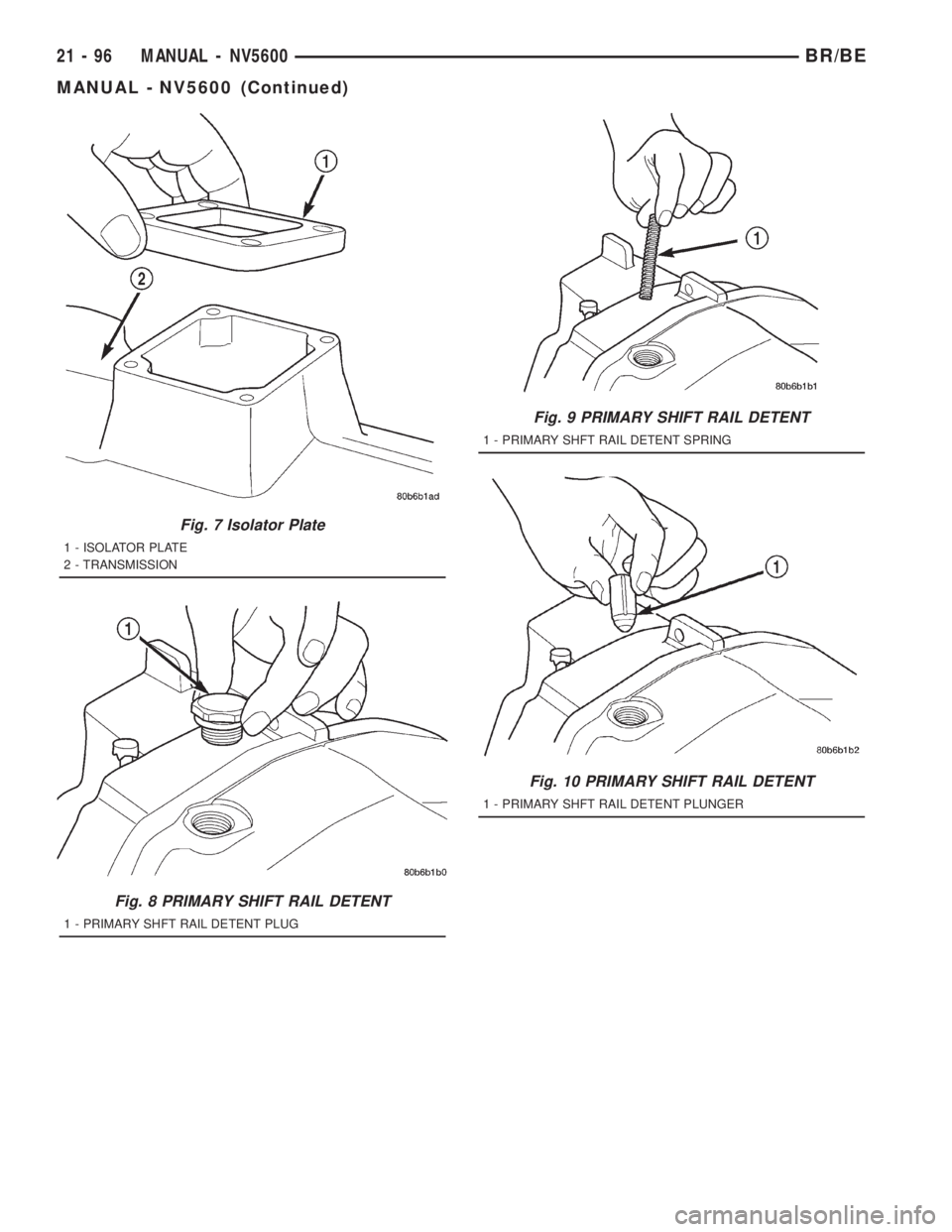
Fig. 7 Isolator Plate
1 - ISOLATOR PLATE
2 - TRANSMISSION
Fig. 8 PRIMARY SHIFT RAIL DETENT
1 - PRIMARY SHFT RAIL DETENT PLUG
Fig. 9 PRIMARY SHIFT RAIL DETENT
1 - PRIMARY SHFT RAIL DETENT SPRING
Fig. 10 PRIMARY SHIFT RAIL DETENT
1 - PRIMARY SHFT RAIL DETENT PLUNGER
21 - 96 MANUAL - NV5600BR/BE
MANUAL - NV5600 (Continued)
Page 1732 of 2889
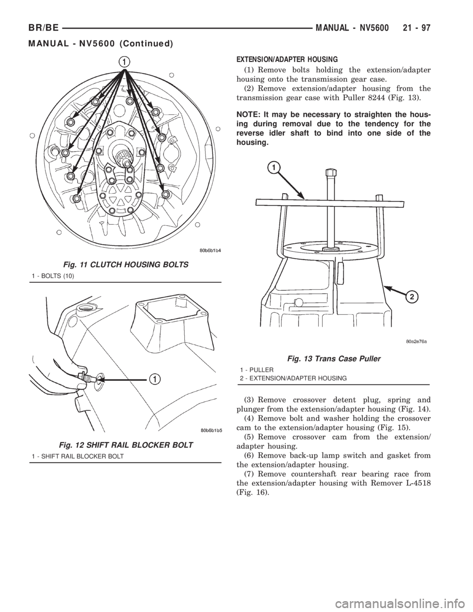
EXTENSION/ADAPTER HOUSING
(1) Remove bolts holding the extension/adapter
housing onto the transmission gear case.
(2) Remove extension/adapter housing from the
transmission gear case with Puller 8244 (Fig. 13).
NOTE: It may be necessary to straighten the hous-
ing during removal due to the tendency for the
reverse idler shaft to bind into one side of the
housing.
(3) Remove crossover detent plug, spring and
plunger from the extension/adapter housing (Fig. 14).
(4) Remove bolt and washer holding the crossover
cam to the extension/adapter housing (Fig. 15).
(5) Remove crossover cam from the extension/
adapter housing.
(6) Remove back-up lamp switch and gasket from
the extension/adapter housing.
(7) Remove countershaft rear bearing race from
the extension/adapter housing with Remover L-4518
(Fig. 16).
Fig. 11 CLUTCH HOUSING BOLTS
1 - BOLTS (10)
Fig. 12 SHIFT RAIL BLOCKER BOLT
1 - SHIFT RAIL BLOCKER BOLT
Fig. 13 Trans Case Puller
1 - PULLER
2 - EXTENSION/ADAPTER HOUSING
BR/BEMANUAL - NV5600 21 - 97
MANUAL - NV5600 (Continued)
Page 1733 of 2889
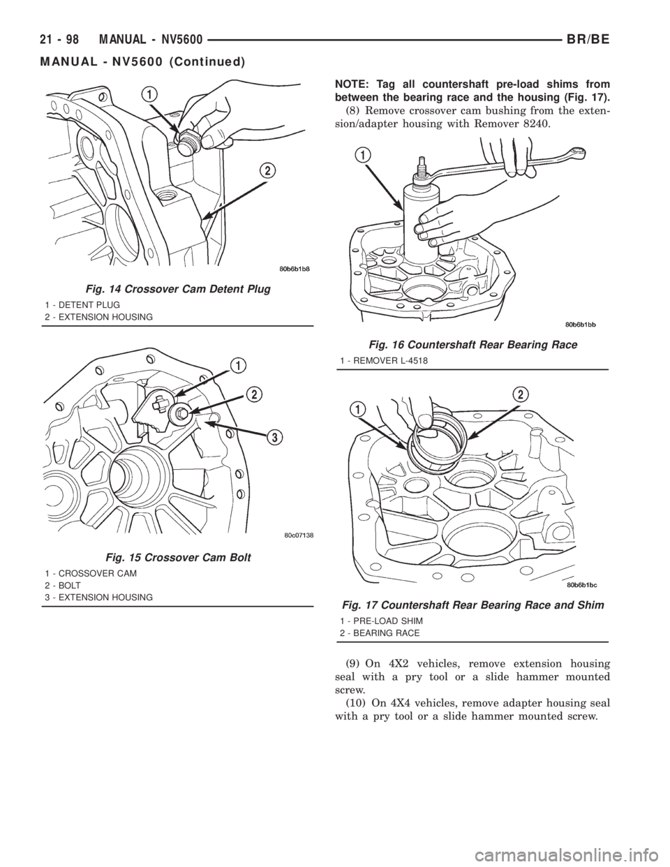
NOTE: Tag all countershaft pre-load shims from
between the bearing race and the housing (Fig. 17).
(8) Remove crossover cam bushing from the exten-
sion/adapter housing with Remover 8240.
(9) On 4X2 vehicles, remove extension housing
seal with a pry tool or a slide hammer mounted
screw.
(10) On 4X4 vehicles, remove adapter housing seal
with a pry tool or a slide hammer mounted screw.
Fig. 14 Crossover Cam Detent Plug
1 - DETENT PLUG
2 - EXTENSION HOUSING
Fig. 15 Crossover Cam Bolt
1 - CROSSOVER CAM
2 - BOLT
3 - EXTENSION HOUSING
Fig. 16 Countershaft Rear Bearing Race
1 - REMOVER L-4518
Fig. 17 Countershaft Rear Bearing Race and Shim
1 - PRE-LOAD SHIM
2 - BEARING RACE
21 - 98 MANUAL - NV5600BR/BE
MANUAL - NV5600 (Continued)
Page 1734 of 2889
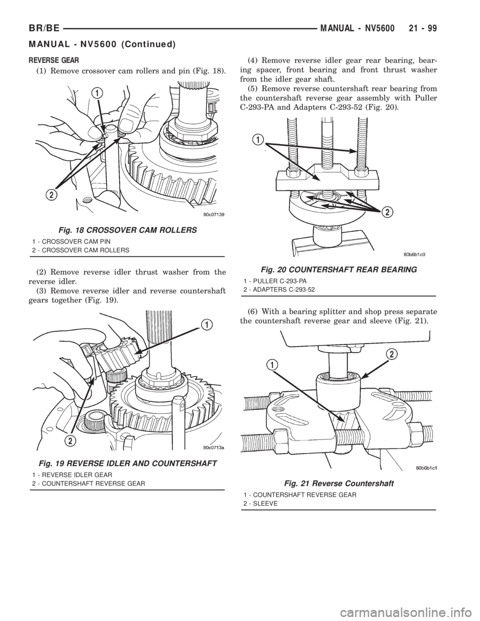
REVERSE GEAR
(1) Remove crossover cam rollers and pin (Fig. 18).
(2) Remove reverse idler thrust washer from the
reverse idler.
(3) Remove reverse idler and reverse countershaft
gears together (Fig. 19).(4) Remove reverse idler gear rear bearing, bear-
ing spacer, front bearing and front thrust washer
from the idler gear shaft.
(5) Remove reverse countershaft rear bearing from
the countershaft reverse gear assembly with Puller
C-293-PA and Adapters C-293-52 (Fig. 20).
(6) With a bearing splitter and shop press separate
the countershaft reverse gear and sleeve (Fig. 21).
Fig. 18 CROSSOVER CAM ROLLERS
1 - CROSSOVER CAM PIN
2 - CROSSOVER CAM ROLLERS
Fig. 19 REVERSE IDLER AND COUNTERSHAFT
1 - REVERSE IDLER GEAR
2 - COUNTERSHAFT REVERSE GEAR
Fig. 20 COUNTERSHAFT REAR BEARING
1 - PULLER C-293-PA
2 - ADAPTERS C-293-52
Fig. 21 Reverse Countershaft
1 - COUNTERSHAFT REVERSE GEAR
2 - SLEEVE
BR/BEMANUAL - NV5600 21 - 99
MANUAL - NV5600 (Continued)
Page 1735 of 2889
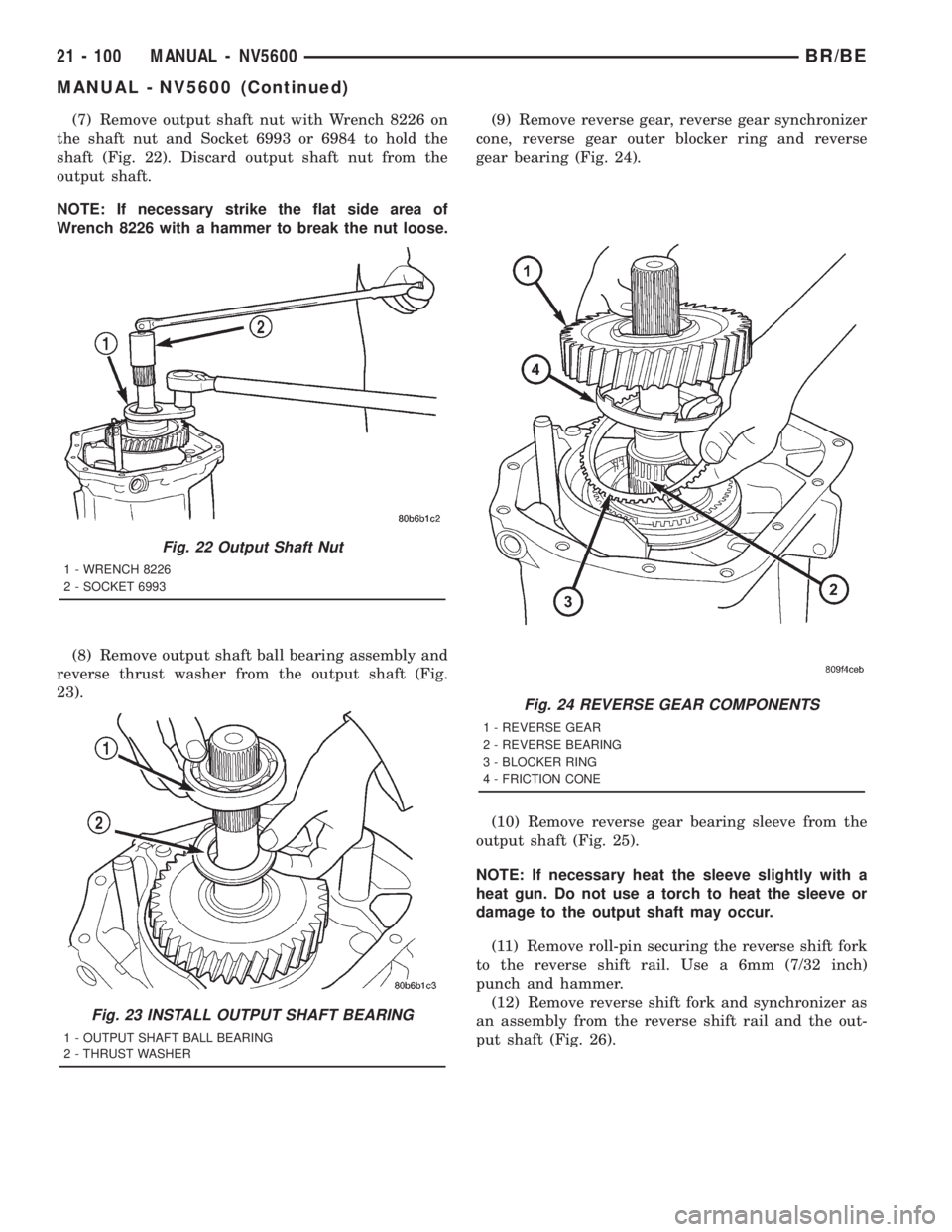
(7) Remove output shaft nut with Wrench 8226 on
the shaft nut and Socket 6993 or 6984 to hold the
shaft (Fig. 22). Discard output shaft nut from the
output shaft.
NOTE: If necessary strike the flat side area of
Wrench 8226 with a hammer to break the nut loose.
(8) Remove output shaft ball bearing assembly and
reverse thrust washer from the output shaft (Fig.
23).(9) Remove reverse gear, reverse gear synchronizer
cone, reverse gear outer blocker ring and reverse
gear bearing (Fig. 24).
(10) Remove reverse gear bearing sleeve from the
output shaft (Fig. 25).
NOTE: If necessary heat the sleeve slightly with a
heat gun. Do not use a torch to heat the sleeve or
damage to the output shaft may occur.
(11) Remove roll-pin securing the reverse shift fork
to the reverse shift rail. Use a 6mm (7/32 inch)
punch and hammer.
(12) Remove reverse shift fork and synchronizer as
an assembly from the reverse shift rail and the out-
put shaft (Fig. 26).
Fig. 22 Output Shaft Nut
1 - WRENCH 8226
2 - SOCKET 6993
Fig. 23 INSTALL OUTPUT SHAFT BEARING
1 - OUTPUT SHAFT BALL BEARING
2 - THRUST WASHER
Fig. 24 REVERSE GEAR COMPONENTS
1 - REVERSE GEAR
2 - REVERSE BEARING
3 - BLOCKER RING
4 - FRICTION CONE
21 - 100 MANUAL - NV5600BR/BE
MANUAL - NV5600 (Continued)
Page 1736 of 2889
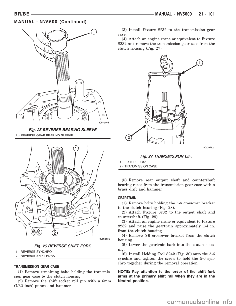
TRANSMISSION GEAR CASE
(1) Remove remaining bolts holding the transmis-
sion gear case to the clutch housing.
(2) Remove the shift socket roll pin with a 6mm
(7/32 inch) punch and hammer.(3) Install Fixture 8232 to the transmission gear
case.
(4) Attach an engine crane or equivalent to Fixture
8232 and remove the transmission gear case from the
clutch housing (Fig. 27).
(5) Remove rear output shaft and countershaft
bearing races from the transmission gear case with a
brass drift and hammer.
GEARTRAIN
(1) Remove bolts holding the 5-6 crossover bracket
to the clutch housing (Fig. 28).
(2) Attach Fixture 8232 to the output shaft and
countershaft (Fig. 29).
(3) Attach an engine crane or equivalent to Fixture
8232 and raise the geartrain approximately 1/4 in.
from the clutch housing.
(4) Remove 5-6 crossover bracket from the clutch
housing.
(5) Lower the geartrain back into the clutch hous-
ing.
(6) Install Holding Tool 8242 (Fig. 30) onto the 5-6
synchro and tighten the screw to hold the 5-6 syn-
chro together during the removal operation.
NOTE: Pay attention to the order of the shift fork
arms at the primary shift rail when they are in the
Neutral position.
Fig. 25 REVERSE BEARING SLEEVE
1 - REVERSE GEAR BEARING SLEEVE
Fig. 26 REVERSE SHIFT FORK
1 - REVERSE SYNCHRO
2 - REVERSE SHIFT FORK
Fig. 27 TRANSMISSION LIFT
1 - FIXTURE 8232
2 - TRANSMISSION CASE
BR/BEMANUAL - NV5600 21 - 101
MANUAL - NV5600 (Continued)
Page 1737 of 2889
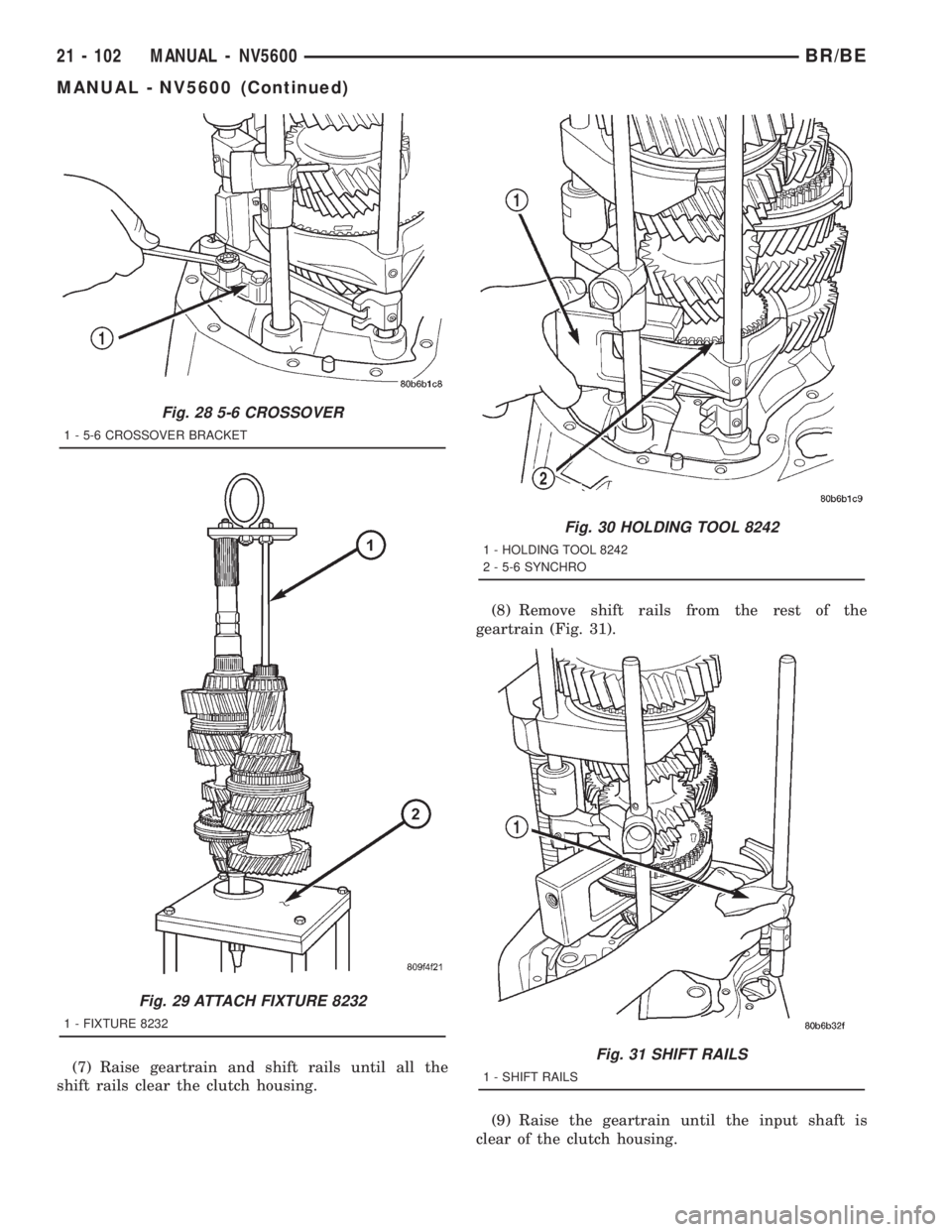
(7) Raise geartrain and shift rails until all the
shift rails clear the clutch housing.(8) Remove shift rails from the rest of the
geartrain (Fig. 31).
(9) Raise the geartrain until the input shaft is
clear of the clutch housing.
Fig. 28 5-6 CROSSOVER
1 - 5-6 CROSSOVER BRACKET
Fig. 29 ATTACH FIXTURE 8232
1 - FIXTURE 8232
Fig. 30 HOLDING TOOL 8242
1 - HOLDING TOOL 8242
2 - 5-6 SYNCHRO
Fig. 31 SHIFT RAILS
1 - SHIFT RAILS
21 - 102 MANUAL - NV5600BR/BE
MANUAL - NV5600 (Continued)
Page 1738 of 2889
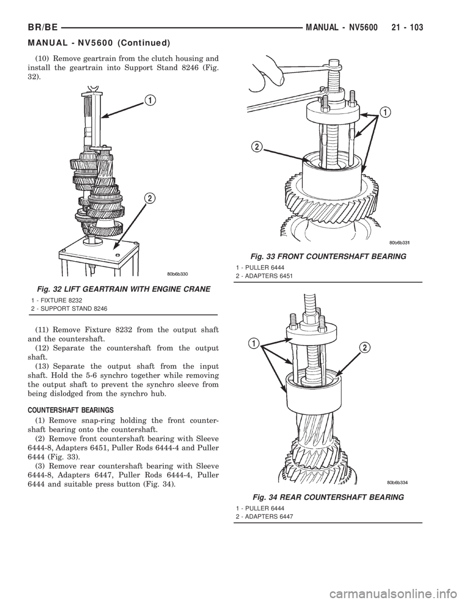
(10) Remove geartrain from the clutch housing and
install the geartrain into Support Stand 8246 (Fig.
32).
(11) Remove Fixture 8232 from the output shaft
and the countershaft.
(12) Separate the countershaft from the output
shaft.
(13) Separate the output shaft from the input
shaft. Hold the 5-6 synchro together while removing
the output shaft to prevent the synchro sleeve from
being dislodged from the synchro hub.
COUNTERSHAFT BEARINGS
(1) Remove snap-ring holding the front counter-
shaft bearing onto the countershaft.
(2) Remove front countershaft bearing with Sleeve
6444-8, Adapters 6451, Puller Rods 6444-4 and Puller
6444 (Fig. 33).
(3) Remove rear countershaft bearing with Sleeve
6444-8, Adapters 6447, Puller Rods 6444-4, Puller
6444 and suitable press button (Fig. 34).
Fig. 32 LIFT GEARTRAIN WITH ENGINE CRANE
1 - FIXTURE 8232
2 - SUPPORT STAND 8246
Fig. 33 FRONT COUNTERSHAFT BEARING
1 - PULLER 6444
2 - ADAPTERS 6451
Fig. 34 REAR COUNTERSHAFT BEARING
1 - PULLER 6444
2 - ADAPTERS 6447
BR/BEMANUAL - NV5600 21 - 103
MANUAL - NV5600 (Continued)
Page 1739 of 2889
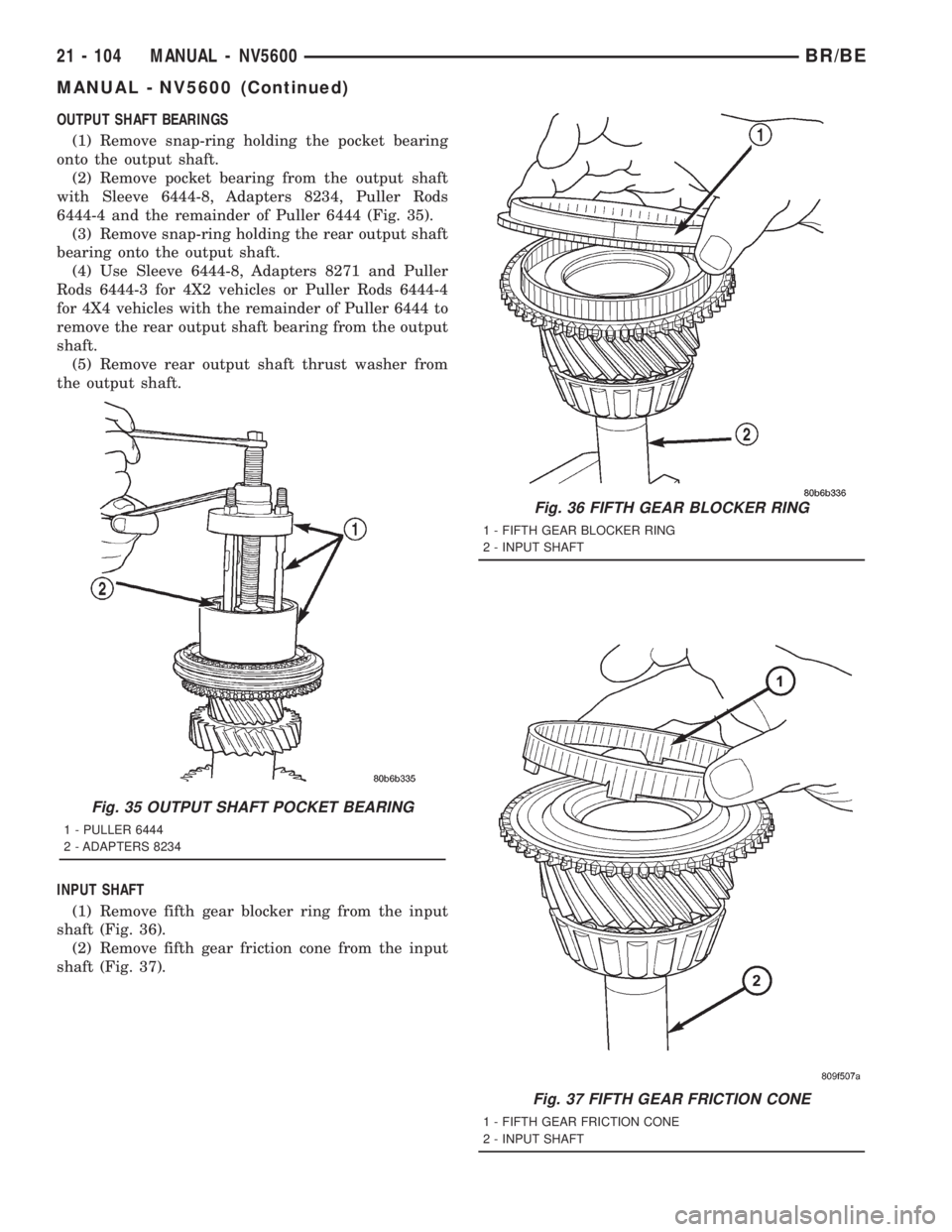
OUTPUT SHAFT BEARINGS
(1) Remove snap-ring holding the pocket bearing
onto the output shaft.
(2) Remove pocket bearing from the output shaft
with Sleeve 6444-8, Adapters 8234, Puller Rods
6444-4 and the remainder of Puller 6444 (Fig. 35).
(3) Remove snap-ring holding the rear output shaft
bearing onto the output shaft.
(4) Use Sleeve 6444-8, Adapters 8271 and Puller
Rods 6444-3 for 4X2 vehicles or Puller Rods 6444-4
for 4X4 vehicles with the remainder of Puller 6444 to
remove the rear output shaft bearing from the output
shaft.
(5) Remove rear output shaft thrust washer from
the output shaft.
INPUT SHAFT
(1) Remove fifth gear blocker ring from the input
shaft (Fig. 36).
(2) Remove fifth gear friction cone from the input
shaft (Fig. 37).
Fig. 35 OUTPUT SHAFT POCKET BEARING
1 - PULLER 6444
2 - ADAPTERS 8234
Fig. 36 FIFTH GEAR BLOCKER RING
1 - FIFTH GEAR BLOCKER RING
2 - INPUT SHAFT
Fig. 37 FIFTH GEAR FRICTION CONE
1 - FIFTH GEAR FRICTION CONE
2 - INPUT SHAFT
21 - 104 MANUAL - NV5600BR/BE
MANUAL - NV5600 (Continued)
Page 1740 of 2889
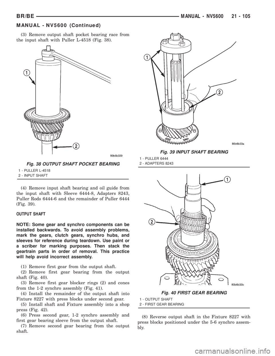
(3) Remove output shaft pocket bearing race from
the input shaft with Puller L-4518 (Fig. 38).
(4) Remove input shaft bearing and oil guide from
the input shaft with Sleeve 6444-8, Adapters 8243,
Puller Rods 6444-6 and the remainder of Puller 6444
(Fig. 39).
OUTPUT SHAFT
NOTE: Some gear and synchro components can be
installed backwards. To avoid assembly problems,
mark the gears, clutch gears, synchro hubs, and
sleeves for reference during teardown. Use paint or
a scriber for marking purposes. Then stack the
geartrain parts in order of removal. This practice
will help avoid incorrect assembly.
(1) Remove first gear from the output shaft.
(2) Remove first gear bearing from the output
shaft (Fig. 40).
(3) Remove first gear blocker rings (2) and cones
from the 1-2 synchro assembly (Fig. 41).
(4) Install the remainder of the output shaft into
Fixture 8227 with press blocks under second gear.
(5) Install shaft and Fixture assembly into a shop
press (Fig. 42).
(6) Press second gear, 1-2 synchro assembly and
first gear bearing sleeve from the output shaft.
(7) Remove second gear bearing from the output
shaft.(8) Reverse output shaft in the Fixture 8227 with
press blocks positioned under the 5-6 synchro assem-
bly.
Fig. 39 INPUT SHAFT BEARING
1 - PULLER 6444
2 - ADAPTERS 8243
Fig. 40 FIRST GEAR BEARING
1 - OUTPUT SHAFT
2 - FIRST GEAR BEARING
Fig. 38 OUTPUT SHAFT POCKET BEARING
1 - PULLER L-4518
2 - INPUT SHAFT
BR/BEMANUAL - NV5600 21 - 105
MANUAL - NV5600 (Continued)