DODGE RAM 2001 Service Repair Manual
Manufacturer: DODGE, Model Year: 2001, Model line: RAM, Model: DODGE RAM 2001Pages: 2889, PDF Size: 68.07 MB
Page 2281 of 2889
CAUTION: It is possible for the park rod to displace
into a cavity just above the pawl sprag during
installation. Make sure the rod is actually engaged
in the pawl and has not displaced into this cavity.
(8) Install accumulator springs and piston into
case. Then swing valve body over piston and outer
spring to hold it in place.
(9) Align accumulator piston and outer spring,
manual lever shaft and electrical connector in case.
(10) Then seat valve body in case and install one
or two bolts to hold valve body in place.
(11) Tighten valve body bolts alternately and
evenly to 11 N´m (100 in. lbs.) torque.
(12) Install new fluid filter on valve body. Tighten
filter screws to 4 N´m (35 in. lbs.) torque.
(13) Install throttle and gearshift levers on valve
body manual lever shaft.
(14) Check and adjust front and rear bands if nec-
essary.
(15) Connect solenoid case connector wires.
(16) Install oil pan and new gasket. Tighten pan
bolts to 17 N´m (13 ft. lbs.) torque.
(17) Lower vehicle and fill transmission with
MopartATF +4, type 9602, fluid.
(18) Check and adjust gearshift and throttle valve
cables, if necessary.
ADJUSTMENTS - VALVE BODY
CONTROL PRESSURE ADJUSTMENTS
There are two control pressure adjustments on the
valve body;
²Line Pressure
²Throttle PressureLine and throttle pressures are interdependent
because each affects shift quality and timing. As a
result, both adjustments must be performed properly
and in the correct sequence. Adjust line pressure first
and throttle pressure last.
LINE PRESSURE ADJUSTMENT
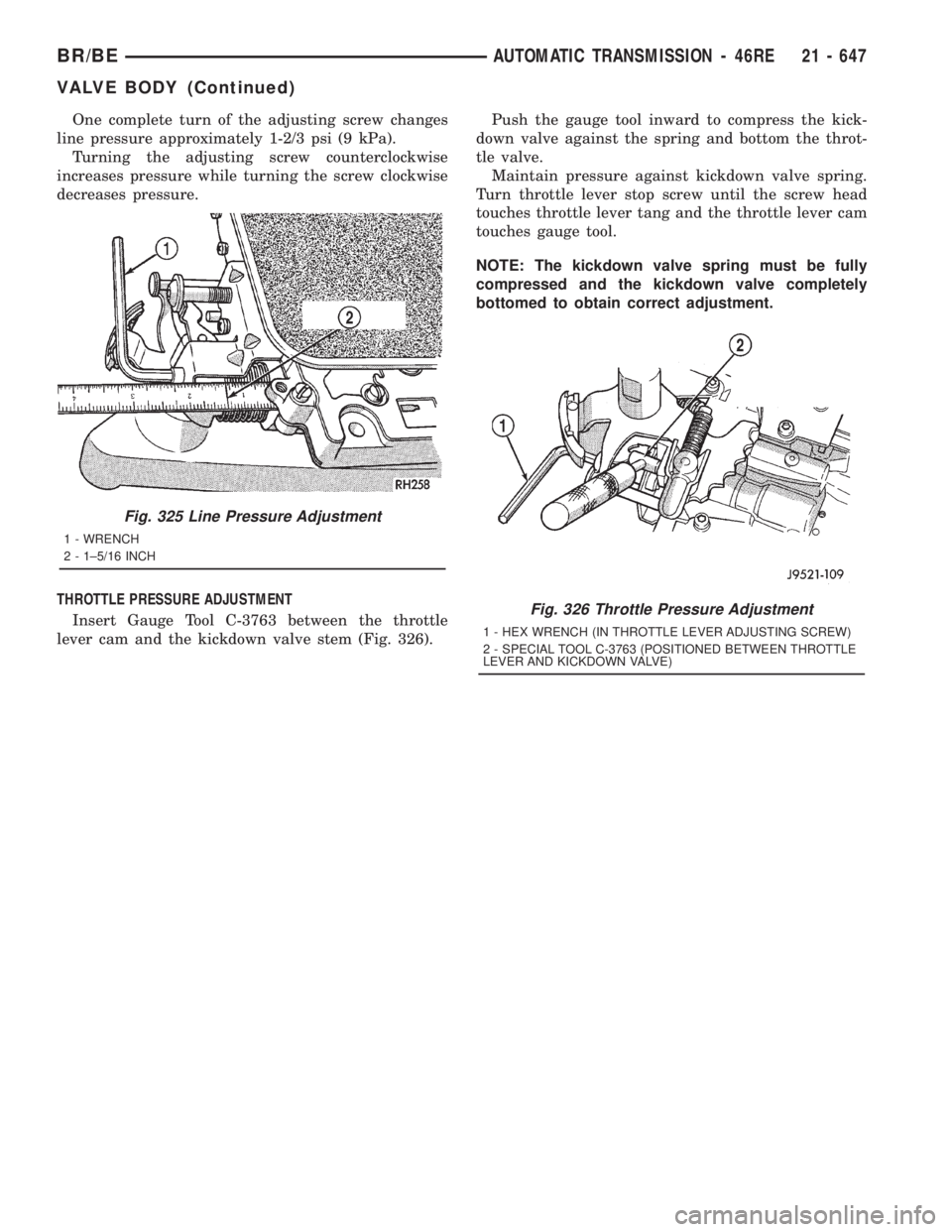
Measure distance from the valve body to the inner
edge of the adjusting screw with an accurate steel
scale (Fig. 325).
Distance should be 33.4 mm (1-5/16 in.).
If adjustment is required, turn the adjusting screw
in, or out, to obtain required distance setting.
NOTE: The 33.4 mm (1-5/16 in.) setting is an
approximate setting. Manufacturing tolerances may
make it necessary to vary from this dimension to
obtain desired pressure.
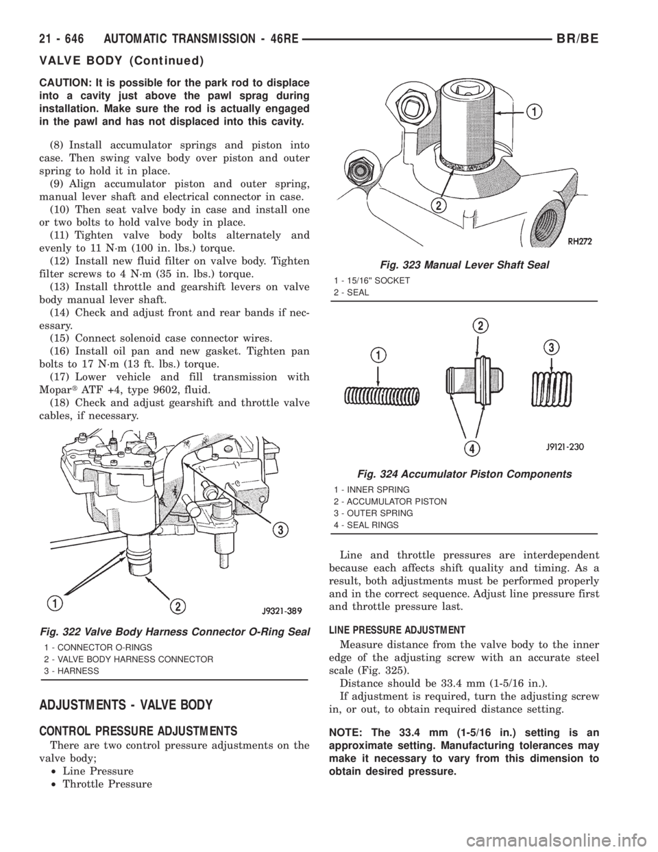
Fig. 322 Valve Body Harness Connector O-Ring Seal
1 - CONNECTOR O-RINGS
2 - VALVE BODY HARNESS CONNECTOR
3 - HARNESS
Fig. 323 Manual Lever Shaft Seal
1 - 15/16©© SOCKET
2 - SEAL
Fig. 324 Accumulator Piston Components
1 - INNER SPRING
2 - ACCUMULATOR PISTON
3 - OUTER SPRING
4 - SEAL RINGS
21 - 646 AUTOMATIC TRANSMISSION - 46REBR/BE
VALVE BODY (Continued)
Page 2282 of 2889
One complete turn of the adjusting screw changes
line pressure approximately 1-2/3 psi (9 kPa).
Turning the adjusting screw counterclockwise
increases pressure while turning the screw clockwise
decreases pressure.
THROTTLE PRESSURE ADJUSTMENT
Insert Gauge Tool C-3763 between the throttle
lever cam and the kickdown valve stem (Fig. 326).Push the gauge tool inward to compress the kick-
down valve against the spring and bottom the throt-
tle valve.
Maintain pressure against kickdown valve spring.
Turn throttle lever stop screw until the screw head
touches throttle lever tang and the throttle lever cam
touches gauge tool.
NOTE: The kickdown valve spring must be fully
compressed and the kickdown valve completely
bottomed to obtain correct adjustment.
Fig. 325 Line Pressure Adjustment
1 - WRENCH
2 - 1±5/16 INCH
Fig. 326 Throttle Pressure Adjustment
1 - HEX WRENCH (IN THROTTLE LEVER ADJUSTING SCREW)
2 - SPECIAL TOOL C-3763 (POSITIONED BETWEEN THROTTLE
LEVER AND KICKDOWN VALVE)
BR/BEAUTOMATIC TRANSMISSION - 46RE 21 - 647
VALVE BODY (Continued)
Page 2283 of 2889
AUTOMATIC TRANSMISSION - 47RE
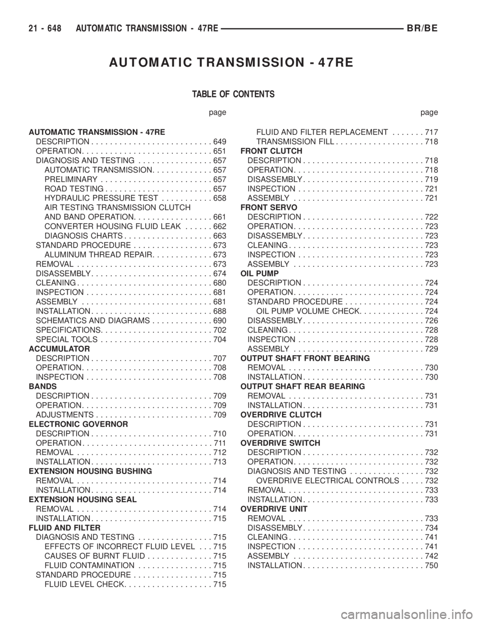
TABLE OF CONTENTS
page page
AUTOMATIC TRANSMISSION - 47RE
DESCRIPTION..........................649
OPERATION............................651
DIAGNOSIS AND TESTING................657
AUTOMATIC TRANSMISSION.............657
PRELIMINARY........................657
ROAD TESTING.......................657
HYDRAULIC PRESSURE TEST...........658
AIR TESTING TRANSMISSION CLUTCH
AND BAND OPERATION.................661
CONVERTER HOUSING FLUID LEAK......662
DIAGNOSIS CHARTS...................663
STANDARD PROCEDURE.................673
ALUMINUM THREAD REPAIR.............673
REMOVAL.............................673
DISASSEMBLY..........................674
CLEANING.............................680
INSPECTION...........................681
ASSEMBLY............................681
INSTALLATION..........................688
SCHEMATICS AND DIAGRAMS.............690
SPECIFICATIONS........................702
SPECIAL TOOLS........................704
ACCUMULATOR
DESCRIPTION..........................707
OPERATION............................708
INSPECTION...........................708
BANDS
DESCRIPTION..........................709
OPERATION............................709
ADJUSTMENTS.........................709
ELECTRONIC GOVERNOR
DESCRIPTION..........................710
OPERATION............................711
REMOVAL.............................712
INSTALLATION..........................713
EXTENSION HOUSING BUSHING
REMOVAL.............................714
INSTALLATION..........................714
EXTENSION HOUSING SEAL
REMOVAL.............................714
INSTALLATION..........................715
FLUID AND FILTER
DIAGNOSIS AND TESTING................715
EFFECTS OF INCORRECT FLUID LEVEL . . . 715
CAUSES OF BURNT FLUID..............715
FLUID CONTAMINATION................715
STANDARD PROCEDURE.................715
FLUID LEVEL CHECK...................715FLUID AND FILTER REPLACEMENT.......717
TRANSMISSION FILL...................718
FRONT CLUTCH
DESCRIPTION..........................718
OPERATION............................718
DISASSEMBLY..........................719
INSPECTION...........................721
ASSEMBLY............................721
FRONT SERVO
DESCRIPTION..........................722
OPERATION............................723
DISASSEMBLY..........................723
CLEANING.............................723
INSPECTION...........................723
ASSEMBLY............................723
OIL PUMP
DESCRIPTION..........................724
OPERATION............................724
STANDARD PROCEDURE.................724
OIL PUMP VOLUME CHECK..............724
DISASSEMBLY..........................726
CLEANING.............................728
INSPECTION...........................728
ASSEMBLY............................729
OUTPUT SHAFT FRONT BEARING
REMOVAL.............................730
INSTALLATION..........................730
OUTPUT SHAFT REAR BEARING
REMOVAL.............................731
INSTALLATION..........................731
OVERDRIVE CLUTCH
DESCRIPTION..........................731
OPERATION............................731
OVERDRIVE SWITCH
DESCRIPTION..........................732
OPERATION............................732
DIAGNOSIS AND TESTING................732
OVERDRIVE ELECTRICAL CONTROLS.....732
REMOVAL.............................733
INSTALLATION..........................733
OVERDRIVE UNIT
REMOVAL.............................733
DISASSEMBLY..........................734
CLEANING.............................741
INSPECTION...........................741
ASSEMBLY............................742
INSTALLATION..........................750
21 - 648 AUTOMATIC TRANSMISSION - 47REBR/BE
Page 2284 of 2889
OVERRUNNING CLUTCH CAM/OVERDRIVE
PISTON RETAINER
DESCRIPTION..........................751
OPERATION............................751
DISASSEMBLY..........................751
CLEANING.............................752
INSPECTION...........................752
ASSEMBLY............................752
PARK/NEUTRAL POSITION SWITCH
DIAGNOSIS AND TESTING................755
PARK/NEUTRAL POSITION SWITCH.......755
REMOVAL.............................755
INSTALLATION..........................755
PISTONS
DESCRIPTION..........................755
OPERATION............................755
PLANETARY GEARTRAIN/OUTPUT SHAFT
DESCRIPTION..........................757
OPERATION............................757
DISASSEMBLY..........................757
INSPECTION...........................760
ASSEMBLY............................760
REAR CLUTCH
DESCRIPTION..........................764
OPERATION............................764
DISASSEMBLY..........................765
CLEANING.............................765
INSPECTION...........................765
ASSEMBLY............................766
REAR SERVO
DESCRIPTION..........................767
OPERATION............................767
DISASSEMBLY..........................768
CLEANING.............................768
ASSEMBLY............................768
SHIFT MECHANISM
DESCRIPTION..........................768OPERATION............................768
ADJUSTMENTS.........................769
SOLENOID
DESCRIPTION..........................769
OPERATION............................770
SPEED SENSOR
DESCRIPTION..........................770
OPERATION............................770
THROTTLE VALVE CABLE
DESCRIPTION..........................770
ADJUSTMENTS.........................771
TORQUE CONVERTER
DESCRIPTION..........................773
OPERATION............................777
REMOVAL.............................778
INSTALLATION..........................778
TORQUE CONVERTER DRAINBACK VALVE
DESCRIPTION..........................778
OPERATION............................778
STANDARD PROCEDURE.................778
TORQUE CONVERTER DRAINBACK VALVE . 778
TRANSMISSION TEMPERATURE SENSOR
DESCRIPTION..........................779
OPERATION............................779
VALVE BODY
DESCRIPTION..........................780
OPERATION............................783
REMOVAL.............................798
DISASSEMBLY..........................799
CLEANING.............................808
INSPECTION...........................809
ASSEMBLY............................810
INSTALLATION..........................818
ADJUSTMENTS.........................818
AUTOMATIC TRANSMISSION -
47RE
DESCRIPTION
The 47RE (Fig. 1) is a four speed fully automatic
transmissions with an electronic governor. The 47RE
is equipped with a lock-up clutch in the torque con-
verter. First through third gear ranges are provided
by the clutches, bands, overrunning clutch, and plan-
etary gear sets in the transmission. Fourth gear
range is provided by the overdrive unit that contains
an overdrive clutch, direct clutch, planetary gear set,
and overrunning clutch.
The transmission contains a front, rear, and direct
clutch which function as the input driving compo-
nents. It also contains the kickdown (front) and thelow/reverse (rear) bands which, along with the over-
running clutch and overdrive clutch, serve as the
holding components. The driving and holding compo-
nents combine to select the necessary planetary gear
components, in the front, rear, or overdrive planetary
gear set, transfer the engine power from the input
shaft through to the output shaft.
The valve body is mounted to the lower side of the
transmission and contains the valves to control pres-
sure regulation, fluid flow control, and clutch/band
application. The oil pump is mounted at the front of
the transmission and is driven by the torque con-
verter hub. The pump supplies the oil pressure nec-
essary for clutch/band actuation and transmission
lubrication.
BR/BEAUTOMATIC TRANSMISSION - 47RE 21 - 649
Page 2285 of 2889
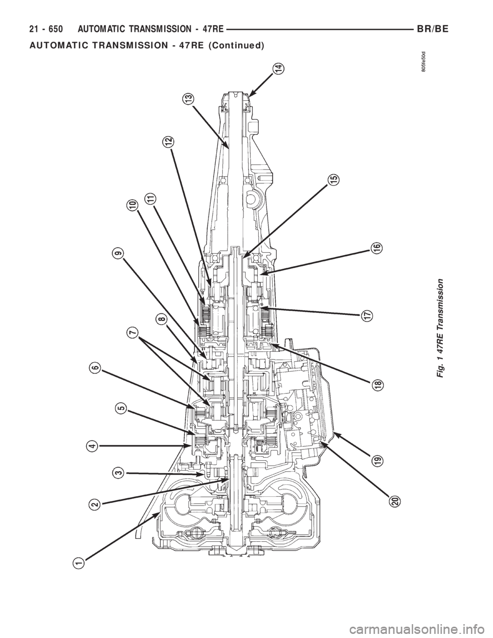
Fig. 1 47RE Transmission
21 - 650 AUTOMATIC TRANSMISSION - 47REBR/BE
AUTOMATIC TRANSMISSION - 47RE (Continued)
Page 2286 of 2889
IDENTIFICATION
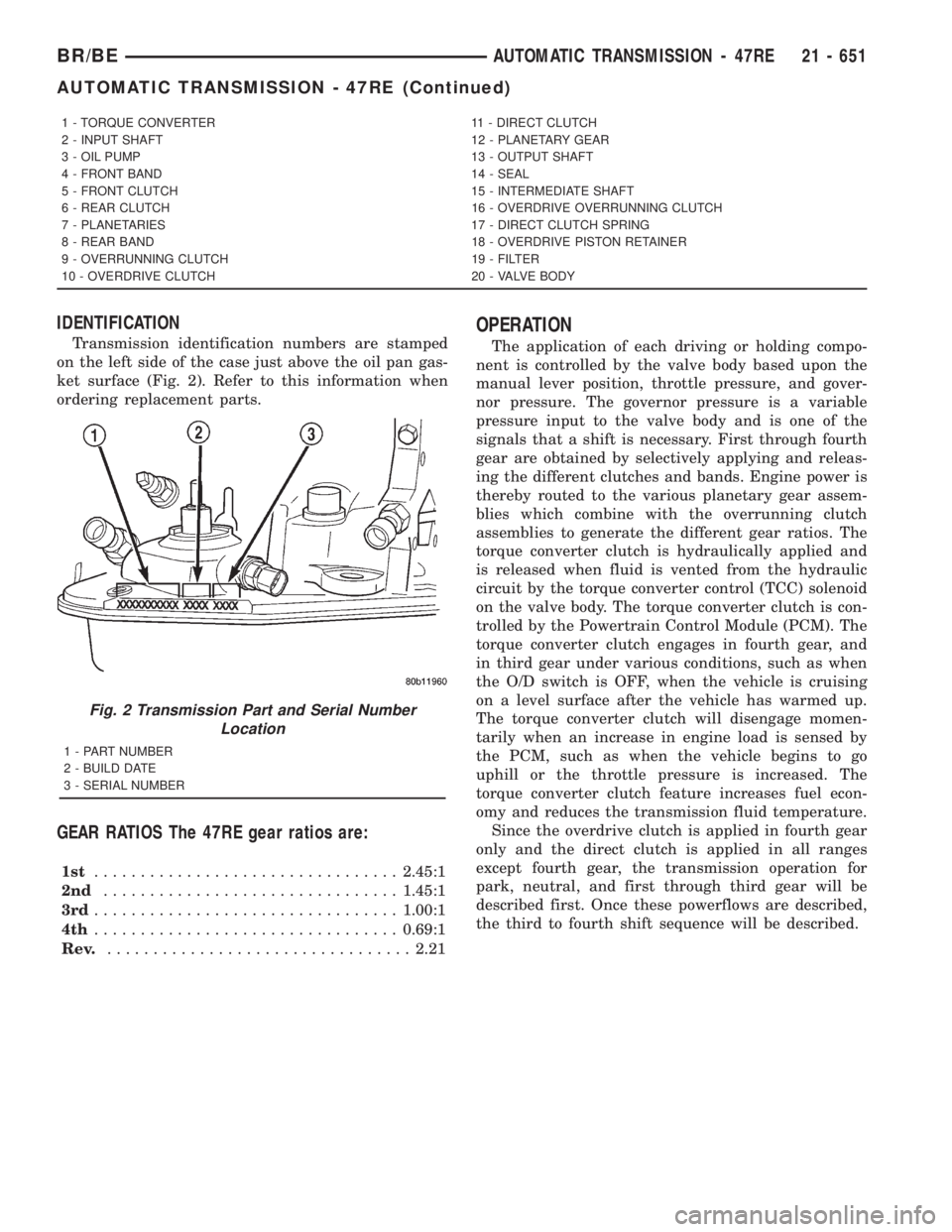
Transmission identification numbers are stamped
on the left side of the case just above the oil pan gas-
ket surface (Fig. 2). Refer to this information when
ordering replacement parts.
GEAR RATIOS The 47RE gear ratios are:
1st.................................2.45:1
2nd................................1.45:1
3rd.................................1.00:1
4th.................................0.69:1
Rev..................................2.21
OPERATION
The application of each driving or holding compo-
nent is controlled by the valve body based upon the
manual lever position, throttle pressure, and gover-
nor pressure. The governor pressure is a variable
pressure input to the valve body and is one of the
signals that a shift is necessary. First through fourth
gear are obtained by selectively applying and releas-
ing the different clutches and bands. Engine power is
thereby routed to the various planetary gear assem-
blies which combine with the overrunning clutch
assemblies to generate the different gear ratios. The
torque converter clutch is hydraulically applied and
is released when fluid is vented from the hydraulic
circuit by the torque converter control (TCC) solenoid
on the valve body. The torque converter clutch is con-
trolled by the Powertrain Control Module (PCM). The
torque converter clutch engages in fourth gear, and
in third gear under various conditions, such as when
the O/D switch is OFF, when the vehicle is cruising
on a level surface after the vehicle has warmed up.
The torque converter clutch will disengage momen-
tarily when an increase in engine load is sensed by
the PCM, such as when the vehicle begins to go
uphill or the throttle pressure is increased. The
torque converter clutch feature increases fuel econ-
omy and reduces the transmission fluid temperature.
Since the overdrive clutch is applied in fourth gear
only and the direct clutch is applied in all ranges
except fourth gear, the transmission operation for
park, neutral, and first through third gear will be
described first. Once these powerflows are described,
the third to fourth shift sequence will be described.
1 - TORQUE CONVERTER 11 - DIRECT CLUTCH
2 - INPUT SHAFT 12 - PLANETARY GEAR
3 - OIL PUMP 13 - OUTPUT SHAFT
4 - FRONT BAND 14 - SEAL
5 - FRONT CLUTCH 15 - INTERMEDIATE SHAFT
6 - REAR CLUTCH 16 - OVERDRIVE OVERRUNNING CLUTCH
7 - PLANETARIES 17 - DIRECT CLUTCH SPRING
8 - REAR BAND 18 - OVERDRIVE PISTON RETAINER
9 - OVERRUNNING CLUTCH 19 - FILTER
10 - OVERDRIVE CLUTCH 20 - VALVE BODY
Fig. 2 Transmission Part and Serial Number
Location
1 - PART NUMBER
2 - BUILD DATE
3 - SERIAL NUMBER
BR/BEAUTOMATIC TRANSMISSION - 47RE 21 - 651
AUTOMATIC TRANSMISSION - 47RE (Continued)
Page 2287 of 2889
PARK POWERFLOW
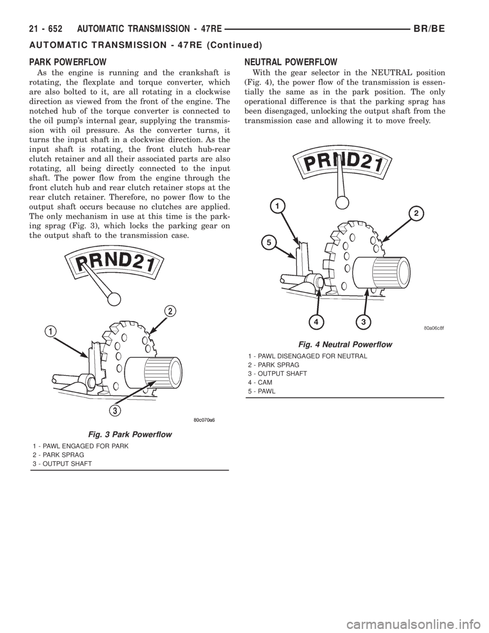
As the engine is running and the crankshaft is
rotating, the flexplate and torque converter, which
are also bolted to it, are all rotating in a clockwise
direction as viewed from the front of the engine. The
notched hub of the torque converter is connected to
the oil pump's internal gear, supplying the transmis-
sion with oil pressure. As the converter turns, it
turns the input shaft in a clockwise direction. As the
input shaft is rotating, the front clutch hub-rear
clutch retainer and all their associated parts are also
rotating, all being directly connected to the input
shaft. The power flow from the engine through the
front clutch hub and rear clutch retainer stops at the
rear clutch retainer. Therefore, no power flow to the
output shaft occurs because no clutches are applied.
The only mechanism in use at this time is the park-
ing sprag (Fig. 3), which locks the parking gear on
the output shaft to the transmission case.
NEUTRAL POWERFLOW
With the gear selector in the NEUTRAL position
(Fig. 4), the power flow of the transmission is essen-
tially the same as in the park position. The only
operational difference is that the parking sprag has
been disengaged, unlocking the output shaft from the
transmission case and allowing it to move freely.
Fig. 3 Park Powerflow
1 - PAWL ENGAGED FOR PARK
2 - PARK SPRAG
3 - OUTPUT SHAFT
Fig. 4 Neutral Powerflow
1 - PAWL DISENGAGED FOR NEUTRAL
2 - PARK SPRAG
3 - OUTPUT SHAFT
4 - CAM
5-PAWL
21 - 652 AUTOMATIC TRANSMISSION - 47REBR/BE
AUTOMATIC TRANSMISSION - 47RE (Continued)
Page 2288 of 2889
REVERSE POWERFLOW
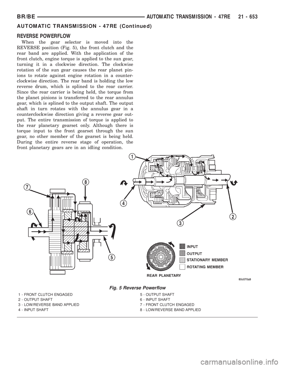
When the gear selector is moved into the
REVERSE position (Fig. 5), the front clutch and the
rear band are applied. With the application of the
front clutch, engine torque is applied to the sun gear,
turning it in a clockwise direction. The clockwise
rotation of the sun gear causes the rear planet pin-
ions to rotate against engine rotation in a counter-
clockwise direction. The rear band is holding the low
reverse drum, which is splined to the rear carrier.
Since the rear carrier is being held, the torque from
the planet pinions is transferred to the rear annulus
gear, which is splined to the output shaft. The output
shaft in turn rotates with the annulus gear in a
counterclockwise direction giving a reverse gear out-
put. The entire transmission of torque is applied to
the rear planetary gearset only. Although there is
torque input to the front gearset through the sun
gear, no other member of the gearset is being held.
During the entire reverse stage of operation, the
front planetary gears are in an idling condition.
Fig. 5 Reverse Powerflow
1 - FRONT CLUTCH ENGAGED 5 - OUTPUT SHAFT
2 - OUTPUT SHAFT 6 - INPUT SHAFT
3 - LOW/REVERSE BAND APPLIED 7 - FRONT CLUTCH ENGAGED
4 - INPUT SHAFT 8 - LOW/REVERSE BAND APPLIED
BR/BEAUTOMATIC TRANSMISSION - 47RE 21 - 653
AUTOMATIC TRANSMISSION - 47RE (Continued)
Page 2289 of 2889
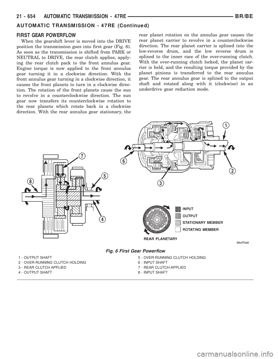
FIRST GEAR POWERFLOW
When the gearshift lever is moved into the DRIVE
position the transmission goes into first gear (Fig. 6).
As soon as the transmission is shifted from PARK or
NEUTRAL to DRIVE, the rear clutch applies, apply-
ing the rear clutch pack to the front annulus gear.
Engine torque is now applied to the front annulus
gear turning it in a clockwise direction. With the
front annulus gear turning in a clockwise direction, it
causes the front planets to turn in a clockwise direc-
tion. The rotation of the front planets cause the sun
to revolve in a counterclockwise direction. The sun
gear now transfers its counterclockwise rotation to
the rear planets which rotate back in a clockwise
direction. With the rear annulus gear stationary, therear planet rotation on the annulus gear causes the
rear planet carrier to revolve in a counterclockwise
direction. The rear planet carrier is splined into the
low-reverse drum, and the low reverse drum is
splined to the inner race of the over-running clutch.
With the over-running clutch locked, the planet car-
rier is held, and the resulting torque provided by the
planet pinions is transferred to the rear annulus
gear. The rear annulus gear is splined to the output
shaft and rotated along with it (clockwise) in an
underdrive gear reduction mode.
Fig. 6 First Gear Powerflow
1 - OUTPUT SHAFT 5 - OVER-RUNNING CLUTCH HOLDING
2 - OVER-RUNNING CLUTCH HOLDING 6 - INPUT SHAFT
3 - REAR CLUTCH APPLIED 7 - REAR CLUTCH APPLIED
4 - OUTPUT SHAFT 8 - INPUT SHAFT
21 - 654 AUTOMATIC TRANSMISSION - 47REBR/BE
AUTOMATIC TRANSMISSION - 47RE (Continued)
Page 2290 of 2889
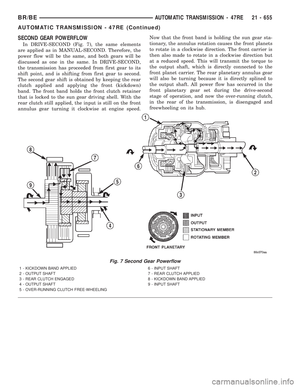
SECOND GEAR POWERFLOW
In DRIVE-SECOND (Fig. 7), the same elements
are applied as in MANUAL-SECOND. Therefore, the
power flow will be the same, and both gears will be
discussed as one in the same. In DRIVE-SECOND,
the transmission has proceeded from first gear to its
shift point, and is shifting from first gear to second.
The second gear shift is obtained by keeping the rear
clutch applied and applying the front (kickdown)
band. The front band holds the front clutch retainer
that is locked to the sun gear driving shell. With the
rear clutch still applied, the input is still on the front
annulus gear turning it clockwise at engine speed.Now that the front band is holding the sun gear sta-
tionary, the annulus rotation causes the front planets
to rotate in a clockwise direction. The front carrier is
then also made to rotate in a clockwise direction but
at a reduced speed. This will transmit the torque to
the output shaft, which is directly connected to the
front planet carrier. The rear planetary annulus gear
will also be turning because it is directly splined to
the output shaft. All power flow has occurred in the
front planetary gear set during the drive-second
stage of operation, and now the over-running clutch,
in the rear of the transmission, is disengaged and
freewheeling on its hub.
Fig. 7 Second Gear Powerflow
1 - KICKDOWN BAND APPLIED 6 - INPUT SHAFT
2 - OUTPUT SHAFT 7 - REAR CLUTCH APPLIED
3 - REAR CLUTCH ENGAGED 8 - KICKDOWN BAND APPLIED
4 - OUTPUT SHAFT 9 - INPUT SHAFT
5 - OVER-RUNNING CLUTCH FREE-WHEELING
BR/BEAUTOMATIC TRANSMISSION - 47RE 21 - 655
AUTOMATIC TRANSMISSION - 47RE (Continued)