DODGE RAM 2001 Service Repair Manual
Manufacturer: DODGE, Model Year: 2001, Model line: RAM, Model: DODGE RAM 2001Pages: 2889, PDF Size: 68.07 MB
Page 221 of 2889
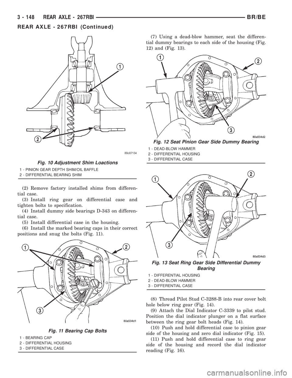
(2) Remove factory installed shims from differen-
tial case.
(3) Install ring gear on differential case and
tighten bolts to specification.
(4) Install dummy side bearings D-343 on differen-
tial case.
(5) Install differential case in the housing.
(6) Install the marked bearing caps in their correct
positions and snug the bolts (Fig. 11).(7) Using a dead-blow hammer, seat the differen-
tial dummy bearings to each side of the housing (Fig.
12) and (Fig. 13).
(8) Thread Pilot Stud C-3288-B into rear cover bolt
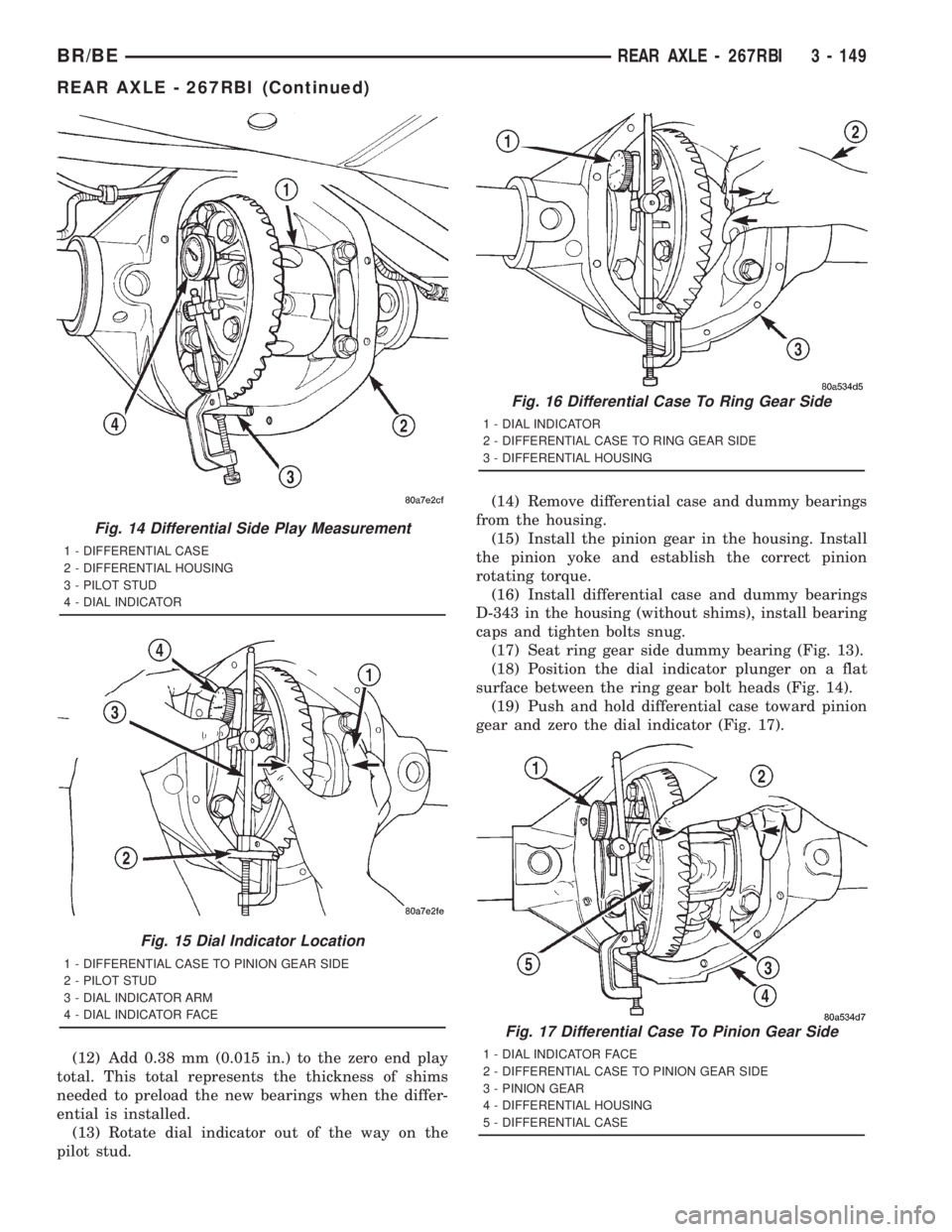
hole below ring gear (Fig. 14).
(9) Attach the Dial Indicator C-3339 to pilot stud.
Position the dial indicator plunger on a flat surface
between the ring gear bolt heads (Fig. 14).
(10) Push and hold differential case to pinion gear
side of the housing and zero dial indicator (Fig. 15).
(11) Push and hold differential case to ring gear
side of the housing and record the dial indicator
reading (Fig. 16).
Fig. 10 Adjustment Shim Loactions
1 - PINION GEAR DEPTH SHIM/OIL BAFFLE
2 - DIFFERENTIAL BEARING SHIM
Fig. 11 Bearing Cap Bolts
1 - BEARING CAP
2 - DIFFERENTIAL HOUSING
3 - DIFFERENTIAL CASE
Fig. 12 Seat Pinion Gear Side Dummy Bearing
1 - DEAD-BLOW HAMMER
2 - DIFFERENTIAL HOUSING
3 - DIFFERENTIAL CASE
Fig. 13 Seat Ring Gear Side Differential Dummy
Bearing
1 - DIFFERENTIAL HOUSING
2 - DEAD-BLOW HAMMER
3 - DIFFERENTIAL CASE
3 - 148 REAR AXLE - 267RBIBR/BE
REAR AXLE - 267RBI (Continued)
Page 222 of 2889
(12) Add 0.38 mm (0.015 in.) to the zero end play
total. This total represents the thickness of shims
needed to preload the new bearings when the differ-
ential is installed.
(13) Rotate dial indicator out of the way on the
pilot stud.(14) Remove differential case and dummy bearings
from the housing.
(15) Install the pinion gear in the housing. Install
the pinion yoke and establish the correct pinion
rotating torque.
(16) Install differential case and dummy bearings
D-343 in the housing (without shims), install bearing
caps and tighten bolts snug.
(17) Seat ring gear side dummy bearing (Fig. 13).
(18) Position the dial indicator plunger on a flat
surface between the ring gear bolt heads (Fig. 14).
(19) Push and hold differential case toward pinion
gear and zero the dial indicator (Fig. 17).
Fig. 14 Differential Side Play Measurement
1 - DIFFERENTIAL CASE
2 - DIFFERENTIAL HOUSING
3 - PILOT STUD
4 - DIAL INDICATOR
Fig. 15 Dial Indicator Location
1 - DIFFERENTIAL CASE TO PINION GEAR SIDE
2 - PILOT STUD
3 - DIAL INDICATOR ARM
4 - DIAL INDICATOR FACE
Fig. 16 Differential Case To Ring Gear Side
1 - DIAL INDICATOR
2 - DIFFERENTIAL CASE TO RING GEAR SIDE
3 - DIFFERENTIAL HOUSING
Fig. 17 Differential Case To Pinion Gear Side
1 - DIAL INDICATOR FACE
2 - DIFFERENTIAL CASE TO PINION GEAR SIDE
3 - PINION GEAR
4 - DIFFERENTIAL HOUSING
5 - DIFFERENTIAL CASE
BR/BEREAR AXLE - 267RBI 3 - 149
REAR AXLE - 267RBI (Continued)
Page 223 of 2889
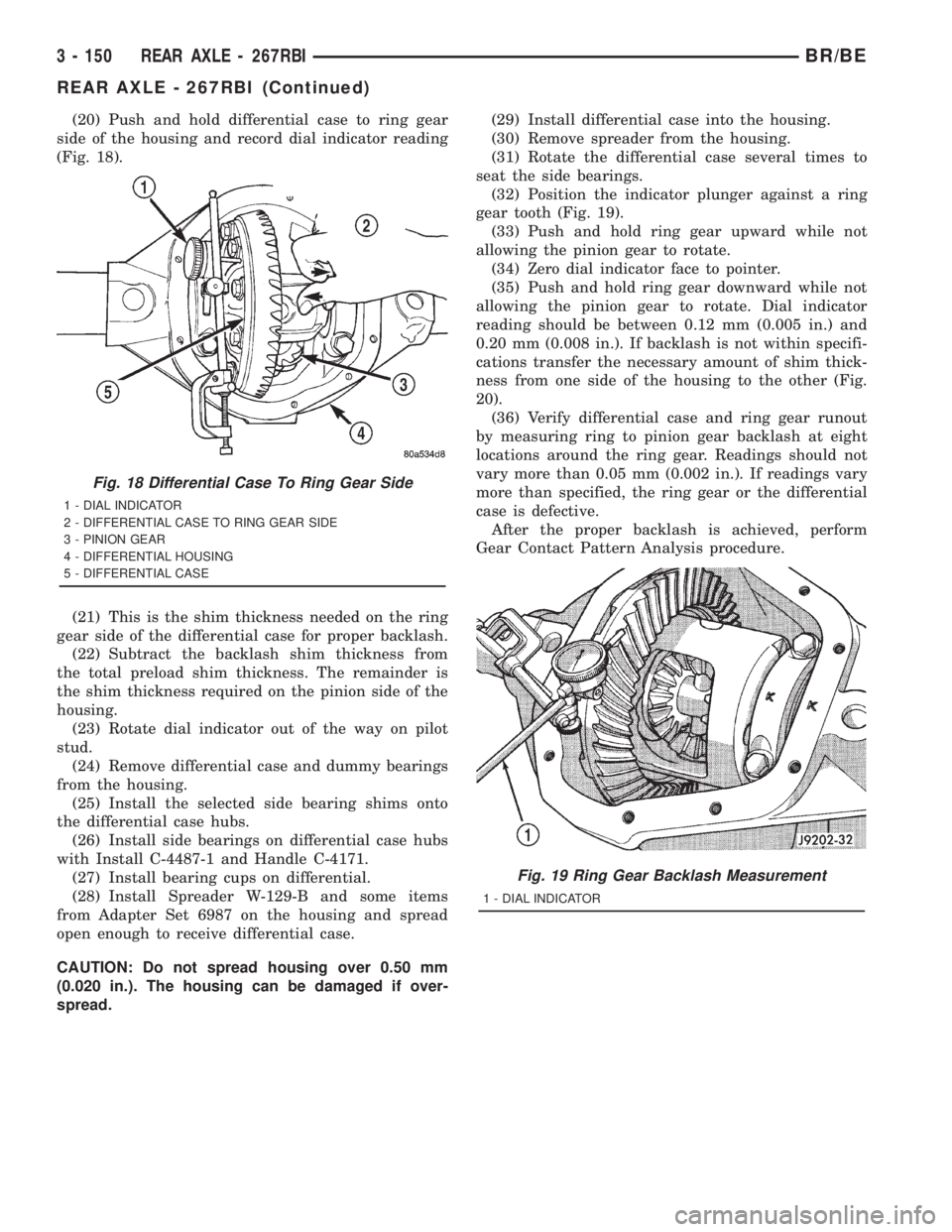
(20) Push and hold differential case to ring gear
side of the housing and record dial indicator reading
(Fig. 18).
(21) This is the shim thickness needed on the ring
gear side of the differential case for proper backlash.
(22) Subtract the backlash shim thickness from
the total preload shim thickness. The remainder is
the shim thickness required on the pinion side of the
housing.
(23) Rotate dial indicator out of the way on pilot
stud.
(24) Remove differential case and dummy bearings
from the housing.
(25) Install the selected side bearing shims onto
the differential case hubs.
(26) Install side bearings on differential case hubs
with Install C-4487-1 and Handle C-4171.
(27) Install bearing cups on differential.
(28) Install Spreader W-129-B and some items
from Adapter Set 6987 on the housing and spread
open enough to receive differential case.
CAUTION: Do not spread housing over 0.50 mm
(0.020 in.). The housing can be damaged if over-
spread.(29) Install differential case into the housing.
(30) Remove spreader from the housing.
(31) Rotate the differential case several times to
seat the side bearings.
(32) Position the indicator plunger against a ring
gear tooth (Fig. 19).
(33) Push and hold ring gear upward while not
allowing the pinion gear to rotate.
(34) Zero dial indicator face to pointer.
(35) Push and hold ring gear downward while not
allowing the pinion gear to rotate. Dial indicator
reading should be between 0.12 mm (0.005 in.) and
0.20 mm (0.008 in.). If backlash is not within specifi-
cations transfer the necessary amount of shim thick-
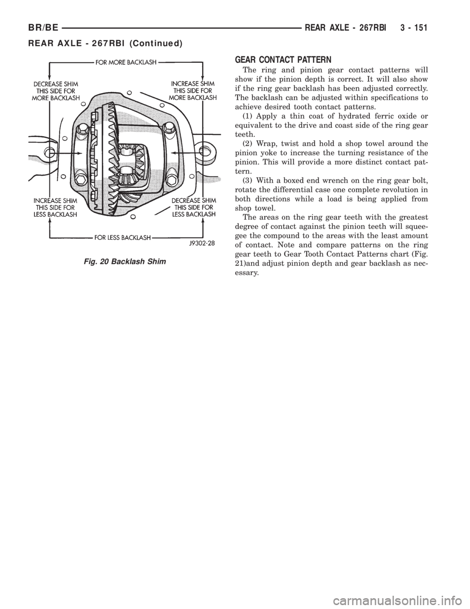
ness from one side of the housing to the other (Fig.
20).
(36) Verify differential case and ring gear runout
by measuring ring to pinion gear backlash at eight
locations around the ring gear. Readings should not
vary more than 0.05 mm (0.002 in.). If readings vary
more than specified, the ring gear or the differential
case is defective.
After the proper backlash is achieved, perform
Gear Contact Pattern Analysis procedure.
Fig. 18 Differential Case To Ring Gear Side
1 - DIAL INDICATOR
2 - DIFFERENTIAL CASE TO RING GEAR SIDE
3 - PINION GEAR
4 - DIFFERENTIAL HOUSING
5 - DIFFERENTIAL CASE
Fig. 19 Ring Gear Backlash Measurement
1 - DIAL INDICATOR
3 - 150 REAR AXLE - 267RBIBR/BE
REAR AXLE - 267RBI (Continued)
Page 224 of 2889
GEAR CONTACT PATTERN
The ring and pinion gear contact patterns will
show if the pinion depth is correct. It will also show
if the ring gear backlash has been adjusted correctly.
The backlash can be adjusted within specifications to
achieve desired tooth contact patterns.
(1) Apply a thin coat of hydrated ferric oxide or
equivalent to the drive and coast side of the ring gear
teeth.
(2) Wrap, twist and hold a shop towel around the
pinion yoke to increase the turning resistance of the
pinion. This will provide a more distinct contact pat-
tern.
(3) With a boxed end wrench on the ring gear bolt,
rotate the differential case one complete revolution in
both directions while a load is being applied from
shop towel.
The areas on the ring gear teeth with the greatest
degree of contact against the pinion teeth will squee-
gee the compound to the areas with the least amount
of contact. Note and compare patterns on the ring
gear teeth to Gear Tooth Contact Patterns chart (Fig.
21)and adjust pinion depth and gear backlash as nec-
essary.
Fig. 20 Backlash Shim
BR/BEREAR AXLE - 267RBI 3 - 151
REAR AXLE - 267RBI (Continued)
Page 225 of 2889
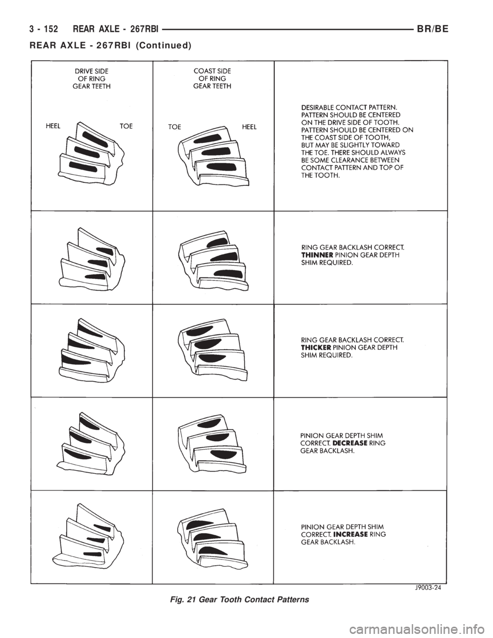
Fig. 21 Gear Tooth Contact Patterns
3 - 152 REAR AXLE - 267RBIBR/BE
REAR AXLE - 267RBI (Continued)
Page 226 of 2889
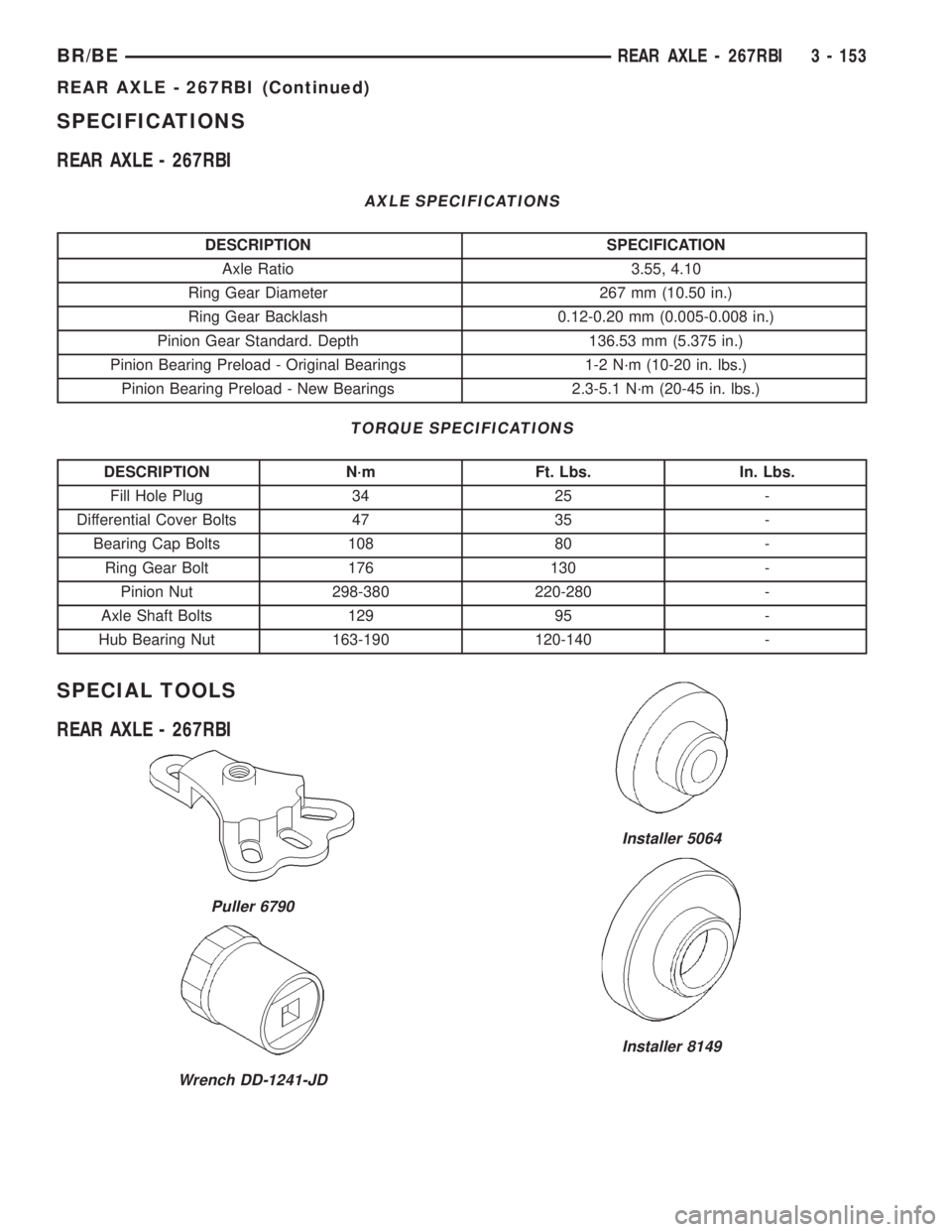
SPECIFICATIONS
REAR AXLE - 267RBI
AXLE SPECIFICATIONS
DESCRIPTION SPECIFICATION
Axle Ratio 3.55, 4.10
Ring Gear Diameter 267 mm (10.50 in.)
Ring Gear Backlash 0.12-0.20 mm (0.005-0.008 in.)
Pinion Gear Standard. Depth 136.53 mm (5.375 in.)
Pinion Bearing Preload - Original Bearings 1-2 N´m (10-20 in. lbs.)
Pinion Bearing Preload - New Bearings 2.3-5.1 N´m (20-45 in. lbs.)
TORQUE SPECIFICATIONS
DESCRIPTION N´m Ft. Lbs. In. Lbs.
Fill Hole Plug 34 25 -
Differential Cover Bolts 47 35 -
Bearing Cap Bolts 108 80 -
Ring Gear Bolt 176 130 -
Pinion Nut 298-380 220-280 -
Axle Shaft Bolts 129 95 -
Hub Bearing Nut 163-190 120-140 -
SPECIAL TOOLS
REAR AXLE - 267RBI
Puller 6790
Wrench DD-1241-JD
Installer 5064
Installer 8149
BR/BEREAR AXLE - 267RBI 3 - 153
REAR AXLE - 267RBI (Continued)
Page 227 of 2889
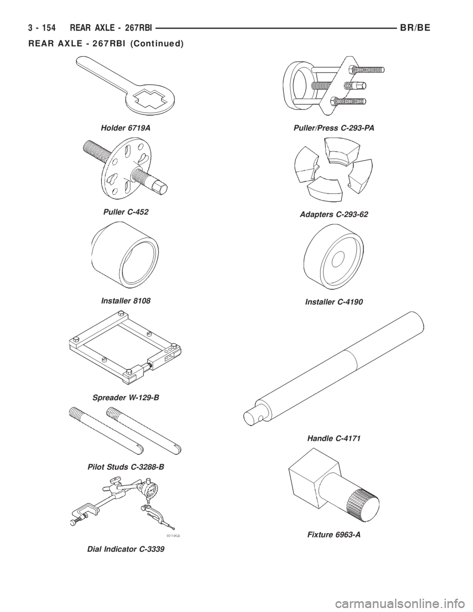
Holder 6719A
Puller C-452
Installer 8108
Spreader W-129-B
Pilot Studs C-3288-B
Dial Indicator C-3339
Puller/Press C-293-PA
Adapters C-293-62
Installer C-4190
Handle C-4171
Fixture 6963-A
3 - 154 REAR AXLE - 267RBIBR/BE
REAR AXLE - 267RBI (Continued)
Page 228 of 2889
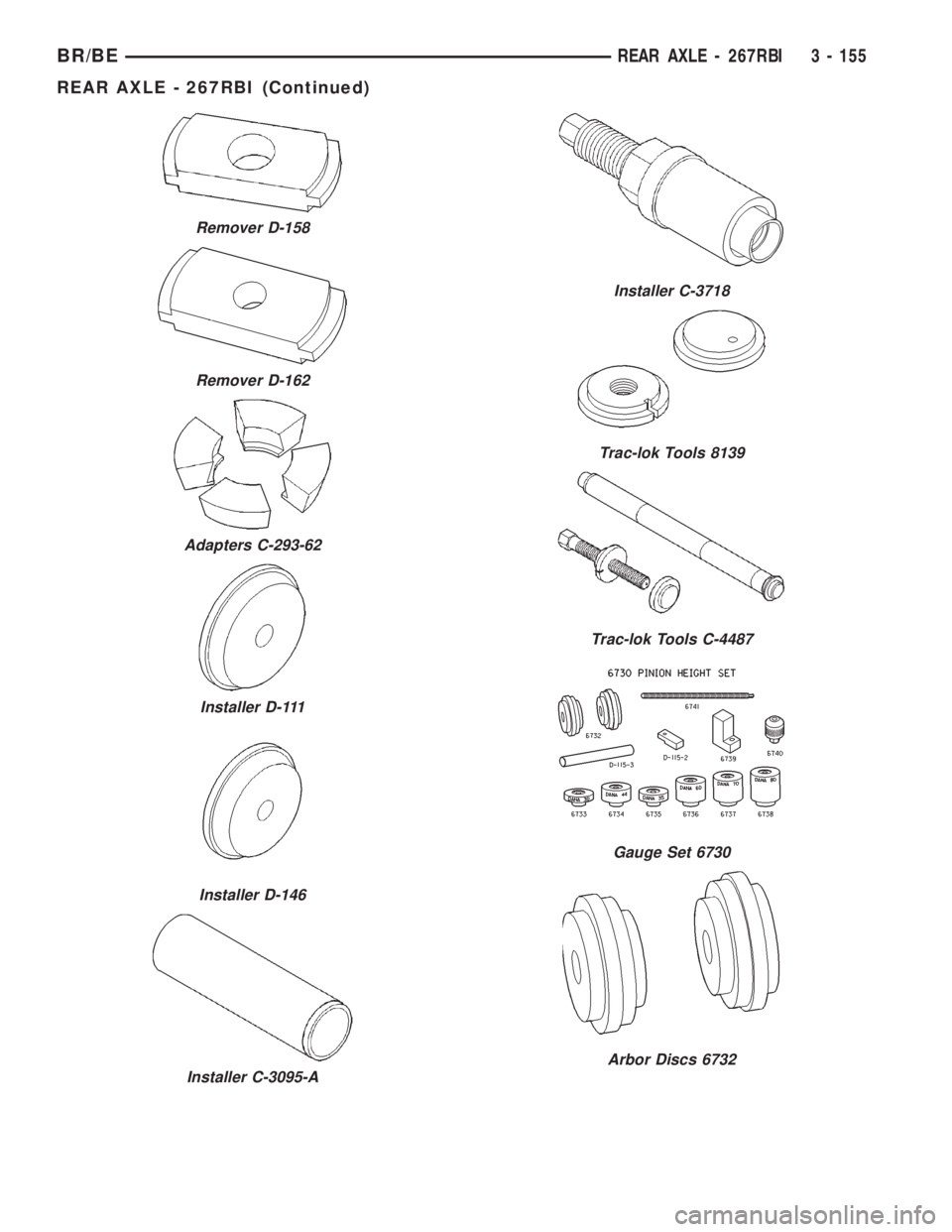
Remover D-158
Remover D-162
Adapters C-293-62
Installer D-111
Installer D-146
Installer C-3095-A
Installer C-3718
Trac-lok Tools 8139
Trac-lok Tools C-4487
Gauge Set 6730
Arbor Discs 6732
BR/BEREAR AXLE - 267RBI 3 - 155
REAR AXLE - 267RBI (Continued)
Page 229 of 2889
AXLE SHAFTS
REMOVAL
(1) Remove the axle shaft flange bolts.
(2) Slide the axle shaft out from the axle tube.
INSTALLATION
(1) Clean the gasket contact surface area on the
flange with an appropriate solvent. Install a new
flange gasket and slide the axle shaft into the tube.
(2) Install the bolts and tighten to 129 N´m (95 ft.
lbs.).
AXLE BEARINGS
REMOVAL
(1) Remove wheel and tire assembly.
(2) Remove brake drum.
(3) Remove the axle shaft.
(4) Remove the lock wedge and adjustment nut.
Use Socket DD-1241±JD to remove the adjustment
nut.
(5) Remove the hub assembly. The outer axle bear-
ing will slide out as the hub is being removed.
(6) Remove inner grease seal and discard. Use
Installer 5064 and Handle C-4171 to drive grease
seal and inner axle bearing from the hub.
(7) Remove the bearing cups from the hub bore.
Use a brass drift, or an appropriate removal tool, to
tap out the cups.
INSTALLATION
(1) Thoroughly clean both axle bearings and inte-
rior of the hub with an appropriate cleaning solvent.
(2) Install bearing cups with Installer 8151 and
Handle C-4171.
(3)Pack inner and outer bearings with
Mopar wheel bearing grease or equivalent.
(4) Apply grease to inner and outer bearing cup
surfaces.
(5) Install inner axle bearing in the hub.
(6) Installnewgrease seal in hub with Installer
8149 and Handle C-4171.
(7) Inspect bearing and seal contact surfaces on
the axle tube for burrs/roughness. Remove all the
rough contact surfaces from the axle tube.
(8) Carefully slide the hub onto the axle.
CAUTION: Do not let grease seal contact axle tube
threads during installtion.
(9) Install outer axle bearing.
(10) Install hub bearing adjustment nut with
Socket DD-1241±JD.(11) Tighten adjustment nut to 163-190 N´m (120-
140 ft. lbs.) while rotating the wheel. Then loosen
adjustment nut 1/8 to 1/3 of-a-turn to provide 0.025-
0.250mm (0.001-0.009 in.) wheel bearing end play.
(12) Tap locking wedge into the spindle keyway
and adjustment nut.
NOTE: Located locking wedge in a new position in
the adjustment nut.
(13) Install axle shaft and brake drum.
(14) Install the wheel and tire assembly.
PINION SEAL
REMOVAL
(1) Raise and support the vehicle.
(2) Scribe a mark on the universal joint, pinion
yoke, and pinion shaft for reference.
(3) Disconnect the propeller shaft from the pinion
yoke. Secure the propeller shaft in an upright posi-
tion to prevent damage to the rear universal joint.
(4) Remove the wheel and tire assemblies.
(5) Remove the brake drums to prevent any drag.
The drag may cause a false bearing preload torque
measurement.
(6) Rotate the pinion yoke three or four times.
(7) Measure the amount of torque necessary to
rotate the pinion gear with a (in. lbs.) dial-type
torque wrench. Record the torque reading for instal-
lation reference.
(8) Hold the yoke with Wrench 6719. Remove the
pinion shaft nut and washer.
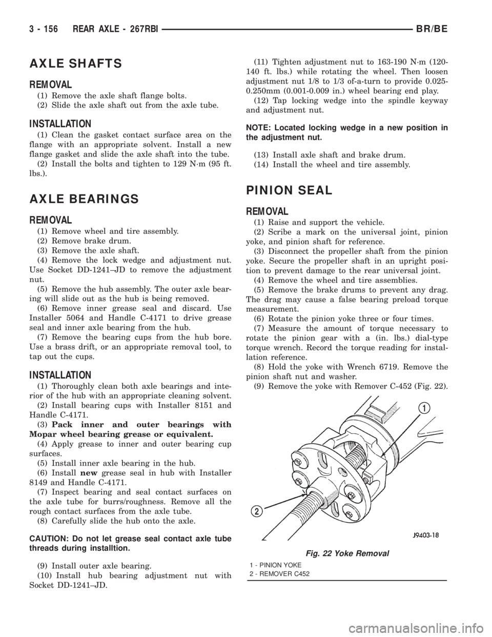
(9) Remove the yoke with Remover C-452 (Fig. 22).
Fig. 22 Yoke Removal
1 - PINION YOKE
2 - REMOVER C452
3 - 156 REAR AXLE - 267RBIBR/BE
Page 230 of 2889
(10) Remove the pinion shaft seal with suitable
pry tool or slide-hammer mounted screw.
INSTALLATION
(1) Clean the seal contact surface in the housing
bore.
(2) Examine the splines on the pinion shaft for
burrs or wear. Remove any burrs and clean the shaft.
NOTE: The outer perimeter of the seal is pre-coated
with a special sealant. An additional application of
sealant is not required.
(3) Apply a light coating of gear lubricant on the
lip of pinion seal.
(4) Install the new pinion shaft seal with an
appropriate installer.
(5) Position the pinion yoke on the end of the shaft
with the reference marks aligned.
(6) Seat yoke on pinion shaft with Installer D-191
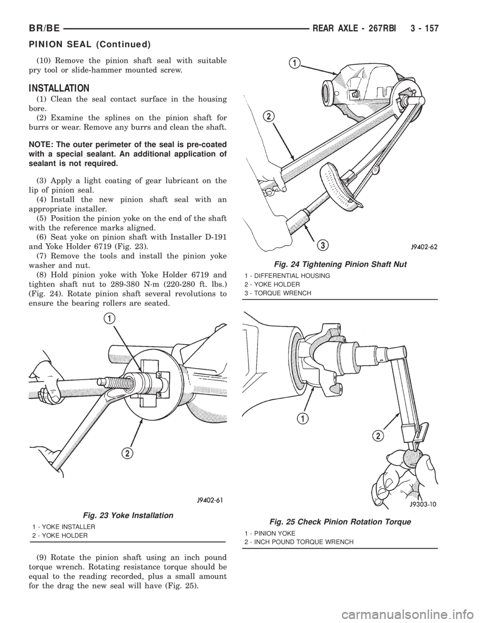
and Yoke Holder 6719 (Fig. 23).
(7) Remove the tools and install the pinion yoke
washer and nut.
(8) Hold pinion yoke with Yoke Holder 6719 and
tighten shaft nut to 289-380 N´m (220-280 ft. lbs.)
(Fig. 24). Rotate pinion shaft several revolutions to
ensure the bearing rollers are seated.
(9) Rotate the pinion shaft using an inch pound
torque wrench. Rotating resistance torque should be
equal to the reading recorded, plus a small amount
for the drag the new seal will have (Fig. 25).
Fig. 23 Yoke Installation
1 - YOKE INSTALLER
2 - YOKE HOLDER
Fig. 24 Tightening Pinion Shaft Nut
1 - DIFFERENTIAL HOUSING
2 - YOKE HOLDER
3 - TORQUE WRENCH
Fig. 25 Check Pinion Rotation Torque
1 - PINION YOKE
2 - INCH POUND TORQUE WRENCH
BR/BEREAR AXLE - 267RBI 3 - 157
PINION SEAL (Continued)