DODGE RAM 2001 Service Repair Manual
Manufacturer: DODGE, Model Year: 2001, Model line: RAM, Model: DODGE RAM 2001Pages: 2889, PDF Size: 68.07 MB
Page 251 of 2889
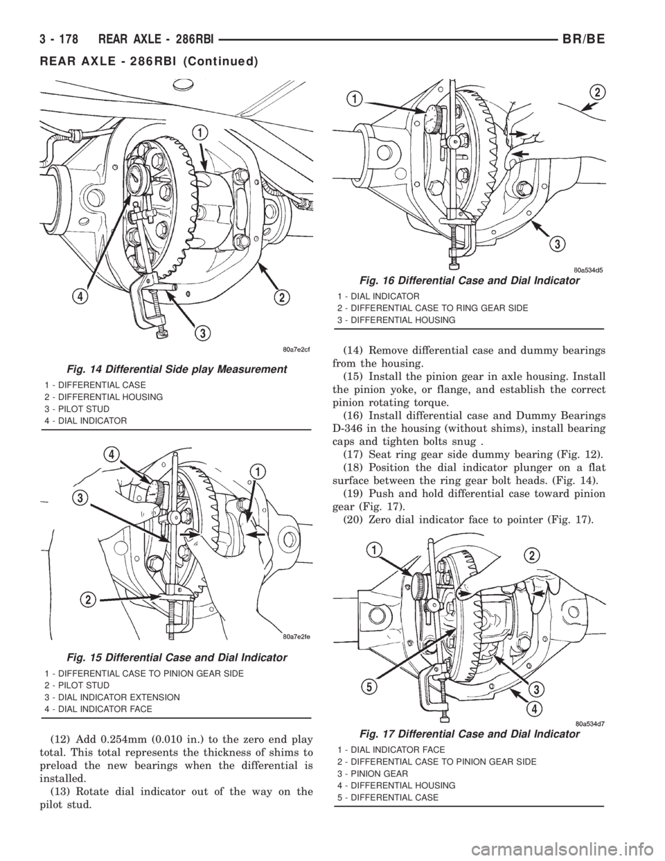
(12) Add 0.254mm (0.010 in.) to the zero end play
total. This total represents the thickness of shims to
preload the new bearings when the differential is
installed.
(13) Rotate dial indicator out of the way on the
pilot stud.(14) Remove differential case and dummy bearings
from the housing.
(15) Install the pinion gear in axle housing. Install
the pinion yoke, or flange, and establish the correct
pinion rotating torque.
(16) Install differential case and Dummy Bearings
D-346 in the housing (without shims), install bearing
caps and tighten bolts snug .
(17) Seat ring gear side dummy bearing (Fig. 12).
(18) Position the dial indicator plunger on a flat
surface between the ring gear bolt heads. (Fig. 14).
(19) Push and hold differential case toward pinion
gear (Fig. 17).
(20) Zero dial indicator face to pointer (Fig. 17).
Fig. 14 Differential Side play Measurement
1 - DIFFERENTIAL CASE
2 - DIFFERENTIAL HOUSING
3 - PILOT STUD
4 - DIAL INDICATOR
Fig. 15 Differential Case and Dial Indicator
1 - DIFFERENTIAL CASE TO PINION GEAR SIDE
2 - PILOT STUD
3 - DIAL INDICATOR EXTENSION
4 - DIAL INDICATOR FACE
Fig. 16 Differential Case and Dial Indicator
1 - DIAL INDICATOR
2 - DIFFERENTIAL CASE TO RING GEAR SIDE
3 - DIFFERENTIAL HOUSING
Fig. 17 Differential Case and Dial Indicator
1 - DIAL INDICATOR FACE
2 - DIFFERENTIAL CASE TO PINION GEAR SIDE
3 - PINION GEAR
4 - DIFFERENTIAL HOUSING
5 - DIFFERENTIAL CASE
3 - 178 REAR AXLE - 286RBIBR/BE
REAR AXLE - 286RBI (Continued)
Page 252 of 2889
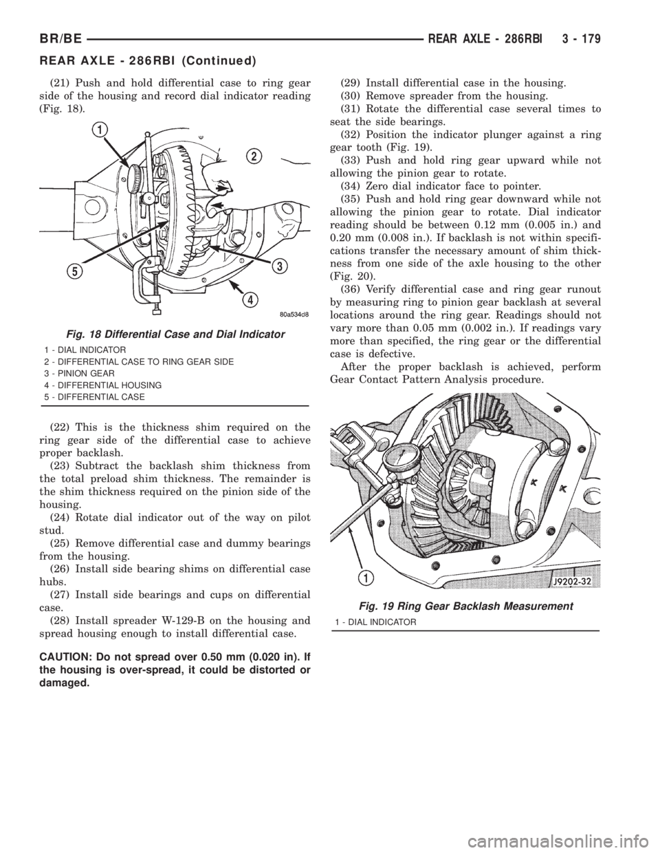
(21) Push and hold differential case to ring gear
side of the housing and record dial indicator reading
(Fig. 18).
(22) This is the thickness shim required on the
ring gear side of the differential case to achieve
proper backlash.
(23) Subtract the backlash shim thickness from
the total preload shim thickness. The remainder is
the shim thickness required on the pinion side of the
housing.
(24) Rotate dial indicator out of the way on pilot
stud.
(25) Remove differential case and dummy bearings
from the housing.
(26) Install side bearing shims on differential case
hubs.
(27) Install side bearings and cups on differential
case.
(28) Install spreader W-129-B on the housing and
spread housing enough to install differential case.
CAUTION: Do not spread over 0.50 mm (0.020 in). If
the housing is over-spread, it could be distorted or
damaged.(29) Install differential case in the housing.
(30) Remove spreader from the housing.
(31) Rotate the differential case several times to
seat the side bearings.
(32) Position the indicator plunger against a ring
gear tooth (Fig. 19).
(33) Push and hold ring gear upward while not
allowing the pinion gear to rotate.
(34) Zero dial indicator face to pointer.
(35) Push and hold ring gear downward while not
allowing the pinion gear to rotate. Dial indicator
reading should be between 0.12 mm (0.005 in.) and
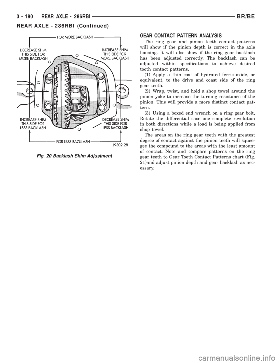
0.20 mm (0.008 in.). If backlash is not within specifi-
cations transfer the necessary amount of shim thick-
ness from one side of the axle housing to the other
(Fig. 20).
(36) Verify differential case and ring gear runout
by measuring ring to pinion gear backlash at several
locations around the ring gear. Readings should not
vary more than 0.05 mm (0.002 in.). If readings vary
more than specified, the ring gear or the differential
case is defective.
After the proper backlash is achieved, perform
Gear Contact Pattern Analysis procedure.
Fig. 18 Differential Case and Dial Indicator
1 - DIAL INDICATOR
2 - DIFFERENTIAL CASE TO RING GEAR SIDE
3 - PINION GEAR
4 - DIFFERENTIAL HOUSING
5 - DIFFERENTIAL CASE
Fig. 19 Ring Gear Backlash Measurement
1 - DIAL INDICATOR
BR/BEREAR AXLE - 286RBI 3 - 179
REAR AXLE - 286RBI (Continued)
Page 253 of 2889
GEAR CONTACT PATTERN ANALYSIS
The ring gear and pinion teeth contact patterns
will show if the pinion depth is correct in the axle
housing. It will also show if the ring gear backlash
has been adjusted correctly. The backlash can be
adjusted within specifications to achieve desired
tooth contact patterns.
(1) Apply a thin coat of hydrated ferric oxide, or
equivalent, to the drive and coast side of the ring
gear teeth.
(2) Wrap, twist, and hold a shop towel around the
pinion yoke to increase the turning resistance of the
pinion. This will provide a more distinct contact pat-
tern.
(3) Using a boxed end wrench on a ring gear bolt,
Rotate the differential case one complete revolution
in both directions while a load is being applied from
shop towel.
The areas on the ring gear teeth with the greatest
degree of contact against the pinion teeth will squee-
gee the compound to the areas with the least amount
of contact. Note and compare patterns on the ring
gear teeth to Gear Tooth Contact Patterns chart (Fig.
21)and adjust pinion depth and gear backlash as nec-
essary.
Fig. 20 Backlash Shim Adjustment
3 - 180 REAR AXLE - 286RBIBR/BE
REAR AXLE - 286RBI (Continued)
Page 254 of 2889
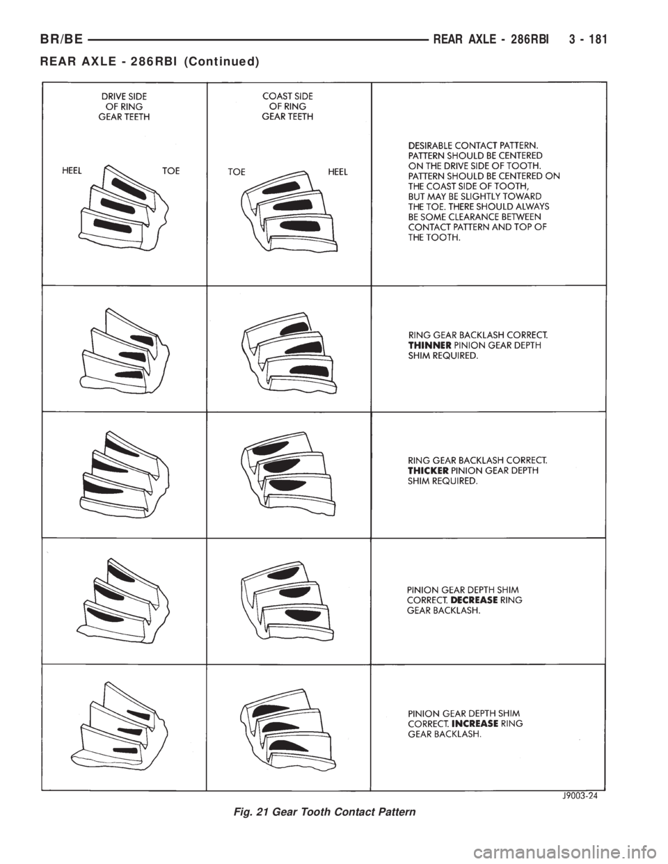
Fig. 21 Gear Tooth Contact Pattern
BR/BEREAR AXLE - 286RBI 3 - 181
REAR AXLE - 286RBI (Continued)
Page 255 of 2889
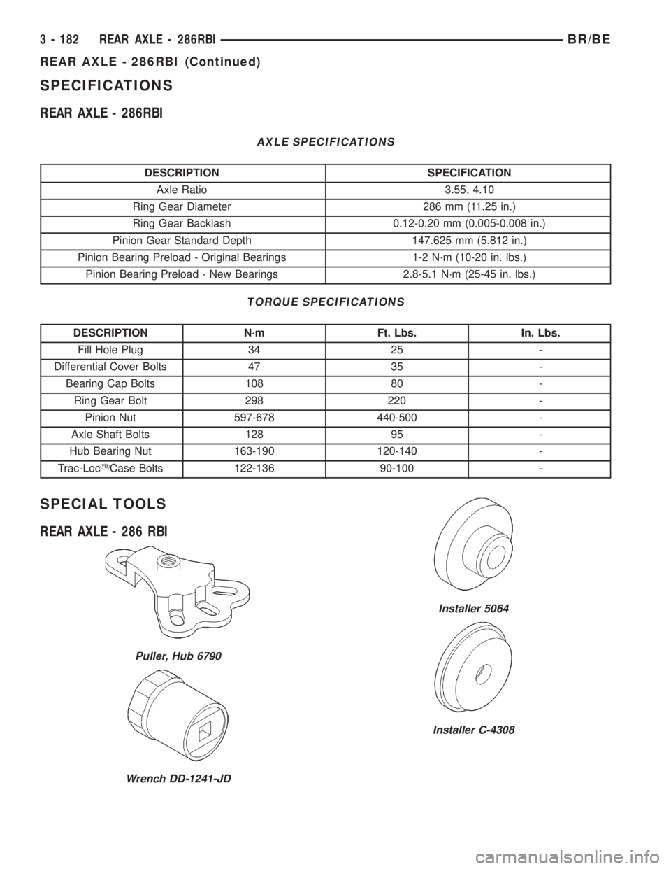
SPECIFICATIONS
REAR AXLE - 286RBI
AXLE SPECIFICATIONS
DESCRIPTION SPECIFICATION
Axle Ratio 3.55, 4.10
Ring Gear Diameter 286 mm (11.25 in.)
Ring Gear Backlash 0.12-0.20 mm (0.005-0.008 in.)
Pinion Gear Standard Depth 147.625 mm (5.812 in.)
Pinion Bearing Preload - Original Bearings 1-2 N´m (10-20 in. lbs.)
Pinion Bearing Preload - New Bearings 2.8-5.1 N´m (25-45 in. lbs.)
TORQUE SPECIFICATIONS
DESCRIPTION N´m Ft. Lbs. In. Lbs.
Fill Hole Plug 34 25 -
Differential Cover Bolts 47 35 -
Bearing Cap Bolts 108 80 -
Ring Gear Bolt 298 220 -
Pinion Nut 597-678 440-500 -
Axle Shaft Bolts 128 95 -
Hub Bearing Nut 163-190 120-140 -
Trac-LocYCase Bolts 122-136 90-100 -
SPECIAL TOOLS
REAR AXLE - 286 RBI
Puller, Hub 6790
Wrench DD-1241-JD
Installer 5064
Installer C-4308
3 - 182 REAR AXLE - 286RBIBR/BE
REAR AXLE - 286RBI (Continued)
Page 256 of 2889
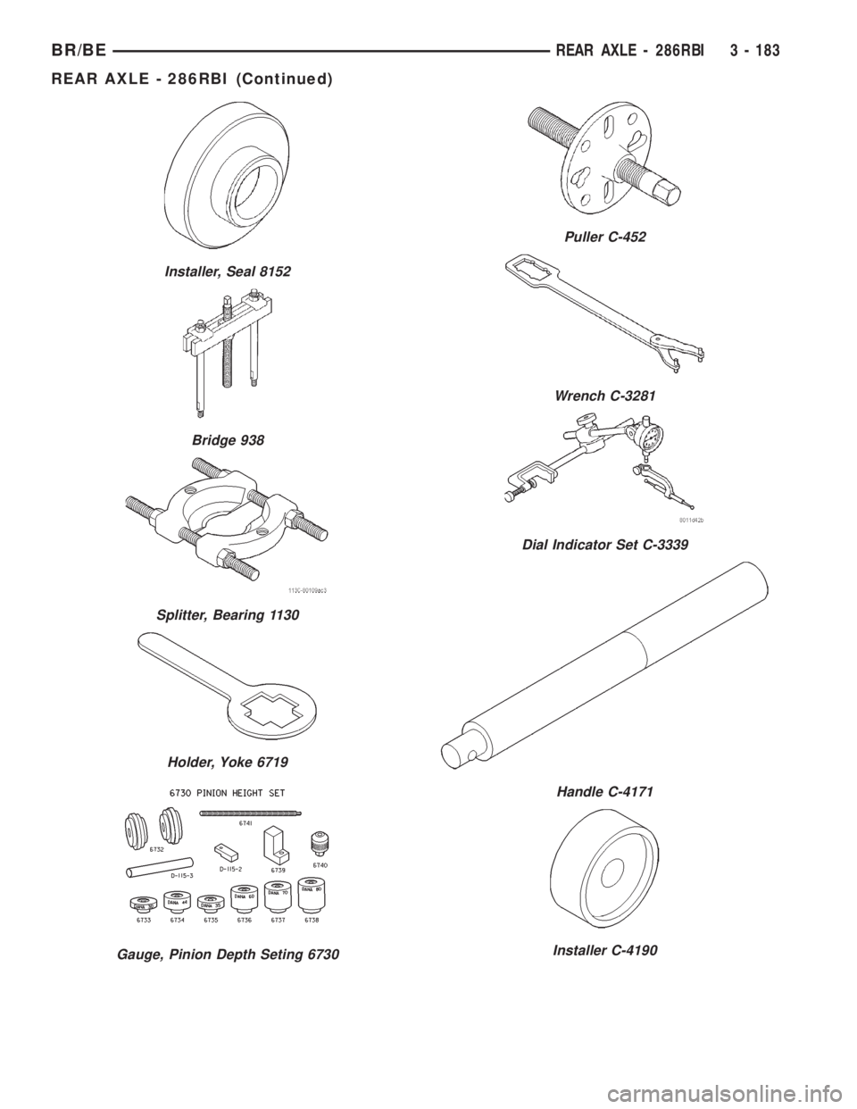
Installer, Seal 8152
Bridge 938
Splitter, Bearing 1130
Holder, Yoke 6719
Gauge, Pinion Depth Seting 6730
Puller C-452
Wrench C-3281
Dial Indicator Set C-3339
Handle C-4171
Installer C-4190
BR/BEREAR AXLE - 286RBI 3 - 183
REAR AXLE - 286RBI (Continued)
Page 257 of 2889
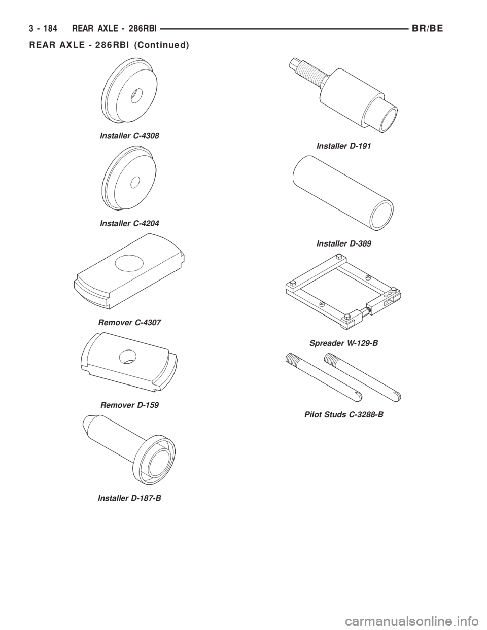
Installer C-4308
Installer C-4204
Remover C-4307
Remover D-159
Installer D-187-B
Installer D-191
Installer D-389
Spreader W-129-B
Pilot Studs C-3288-B
3 - 184 REAR AXLE - 286RBIBR/BE
REAR AXLE - 286RBI (Continued)
Page 258 of 2889
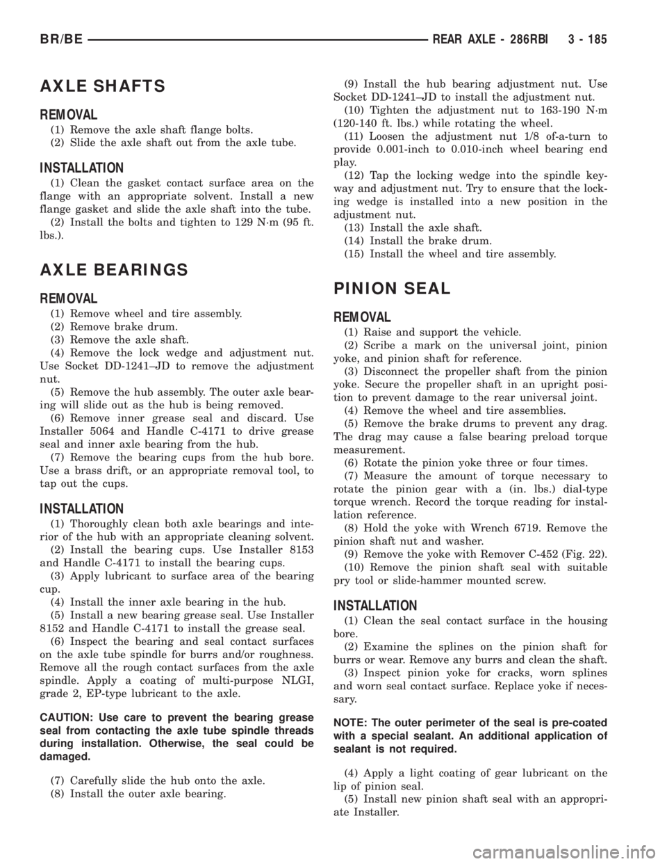
AXLE SHAFTS
REMOVAL
(1) Remove the axle shaft flange bolts.
(2) Slide the axle shaft out from the axle tube.
INSTALLATION
(1) Clean the gasket contact surface area on the
flange with an appropriate solvent. Install a new
flange gasket and slide the axle shaft into the tube.
(2) Install the bolts and tighten to 129 N´m (95 ft.
lbs.).
AXLE BEARINGS
REMOVAL
(1) Remove wheel and tire assembly.
(2) Remove brake drum.
(3) Remove the axle shaft.
(4) Remove the lock wedge and adjustment nut.
Use Socket DD-1241±JD to remove the adjustment
nut.
(5) Remove the hub assembly. The outer axle bear-
ing will slide out as the hub is being removed.
(6) Remove inner grease seal and discard. Use
Installer 5064 and Handle C-4171 to drive grease
seal and inner axle bearing from the hub.
(7) Remove the bearing cups from the hub bore.
Use a brass drift, or an appropriate removal tool, to
tap out the cups.
INSTALLATION
(1) Thoroughly clean both axle bearings and inte-
rior of the hub with an appropriate cleaning solvent.
(2) Install the bearing cups. Use Installer 8153
and Handle C-4171 to install the bearing cups.
(3) Apply lubricant to surface area of the bearing
cup.
(4) Install the inner axle bearing in the hub.
(5) Install a new bearing grease seal. Use Installer
8152 and Handle C-4171 to install the grease seal.
(6) Inspect the bearing and seal contact surfaces
on the axle tube spindle for burrs and/or roughness.
Remove all the rough contact surfaces from the axle
spindle. Apply a coating of multi-purpose NLGI,
grade 2, EP-type lubricant to the axle.
CAUTION: Use care to prevent the bearing grease
seal from contacting the axle tube spindle threads
during installation. Otherwise, the seal could be
damaged.
(7) Carefully slide the hub onto the axle.
(8) Install the outer axle bearing.(9) Install the hub bearing adjustment nut. Use
Socket DD-1241±JD to install the adjustment nut.
(10) Tighten the adjustment nut to 163-190 N´m
(120-140 ft. lbs.) while rotating the wheel.
(11) Loosen the adjustment nut 1/8 of-a-turn to
provide 0.001-inch to 0.010-inch wheel bearing end
play.
(12) Tap the locking wedge into the spindle key-
way and adjustment nut. Try to ensure that the lock-
ing wedge is installed into a new position in the
adjustment nut.
(13) Install the axle shaft.
(14) Install the brake drum.
(15) Install the wheel and tire assembly.
PINION SEAL
REMOVAL
(1) Raise and support the vehicle.
(2) Scribe a mark on the universal joint, pinion
yoke, and pinion shaft for reference.
(3) Disconnect the propeller shaft from the pinion
yoke. Secure the propeller shaft in an upright posi-
tion to prevent damage to the rear universal joint.
(4) Remove the wheel and tire assemblies.
(5) Remove the brake drums to prevent any drag.
The drag may cause a false bearing preload torque
measurement.
(6) Rotate the pinion yoke three or four times.
(7) Measure the amount of torque necessary to
rotate the pinion gear with a (in. lbs.) dial-type
torque wrench. Record the torque reading for instal-
lation reference.
(8) Hold the yoke with Wrench 6719. Remove the
pinion shaft nut and washer.
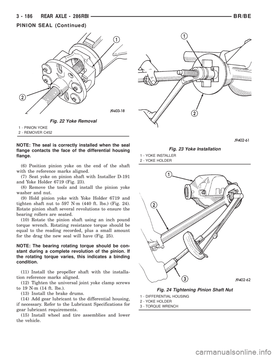
(9) Remove the yoke with Remover C-452 (Fig. 22).
(10) Remove the pinion shaft seal with suitable
pry tool or slide-hammer mounted screw.
INSTALLATION
(1) Clean the seal contact surface in the housing
bore.
(2) Examine the splines on the pinion shaft for
burrs or wear. Remove any burrs and clean the shaft.
(3) Inspect pinion yoke for cracks, worn splines
and worn seal contact surface. Replace yoke if neces-
sary.
NOTE: The outer perimeter of the seal is pre-coated
with a special sealant. An additional application of
sealant is not required.
(4) Apply a light coating of gear lubricant on the
lip of pinion seal.
(5) Install new pinion shaft seal with an appropri-
ate Installer.
BR/BEREAR AXLE - 286RBI 3 - 185
Page 259 of 2889
NOTE: The seal is correctly installed when the seal
flange contacts the face of the differential housing
flange.
(6) Position pinion yoke on the end of the shaft
with the reference marks aligned.
(7) Seat yoke on pinion shaft with Installer D-191
and Yoke Holder 6719 (Fig. 23).
(8) Remove the tools and install the pinion yoke
washer and nut.
(9) Hold pinion yoke with Yoke Holder 6719 and
tighten shaft nut to 597 N´m (440 ft. lbs.) (Fig. 24).
Rotate pinion shaft several revolutions to ensure the
bearing rollers are seated.
(10) Rotate the pinion shaft using an inch pound
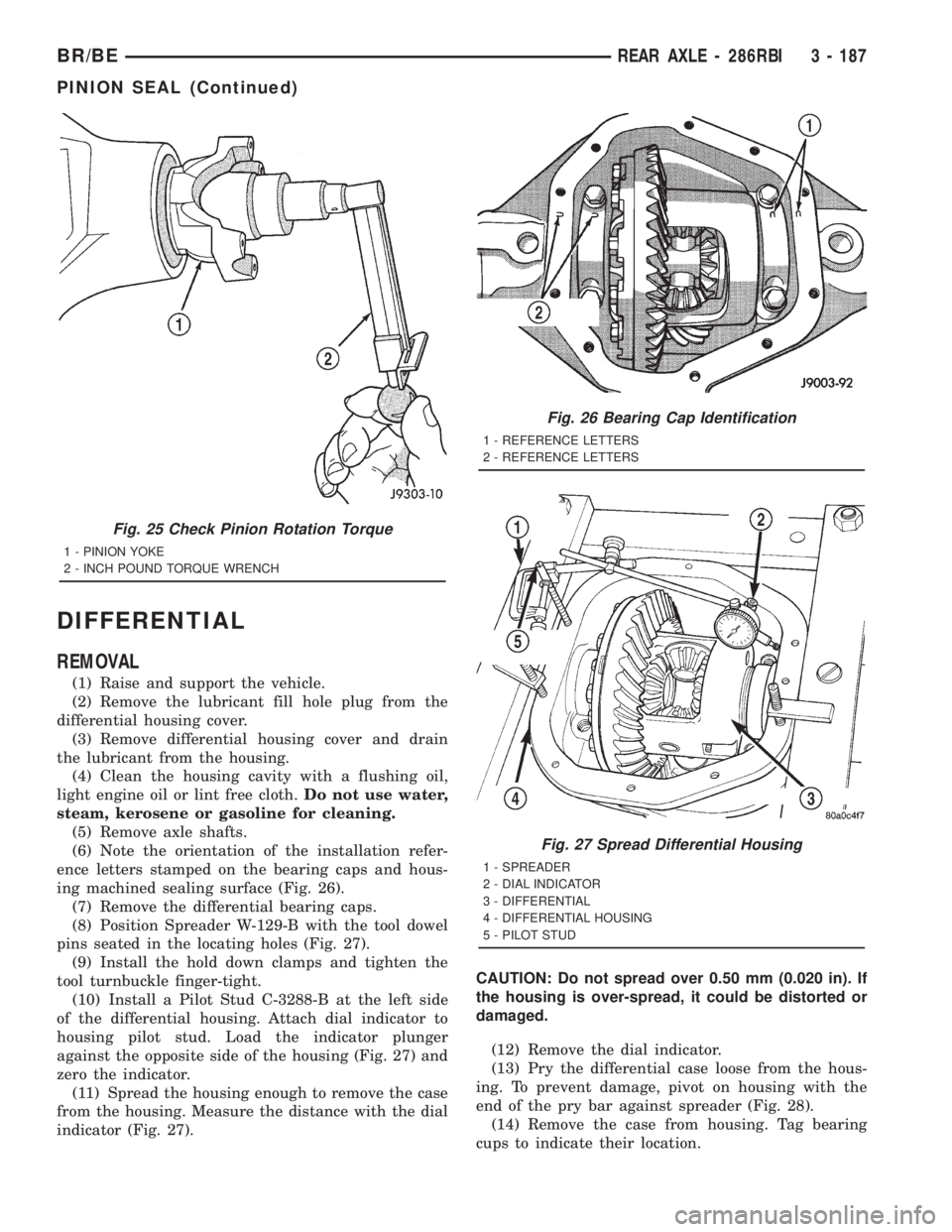
torque wrench. Rotating resistance torque should be
equal to the reading recorded, plus a small amount
for the drag the new seal will have (Fig. 25).
NOTE: The bearing rotating torque should be con-
stant during a complete revolution of the pinion. If
the rotating torque varies, this indicates a binding
condition.
(11) Install the propeller shaft with the installa-
tion reference marks aligned.
(12) Tighten the universal joint yoke clamp screws
to 19 N´m (14 ft. lbs.).
(13) Install the brake drums.
(14) Add gear lubricant to the differential housing,
if necessary. Refer to the Lubricant Specifications for
gear lubricant requirements.
(15) Install wheel and tire assemblies and lower
the vehicle.
Fig. 22 Yoke Removal
1 - PINION YOKE
2 - REMOVER C452
Fig. 23 Yoke Installation
1 - YOKE INSTALLER
2 - YOKE HOLDER
Fig. 24 Tightening Pinion Shaft Nut
1 - DIFFERENTIAL HOUSING
2 - YOKE HOLDER
3 - TORQUE WRENCH
3 - 186 REAR AXLE - 286RBIBR/BE
PINION SEAL (Continued)
Page 260 of 2889
DIFFERENTIAL
REMOVAL
(1) Raise and support the vehicle.
(2) Remove the lubricant fill hole plug from the
differential housing cover.
(3) Remove differential housing cover and drain
the lubricant from the housing.
(4) Clean the housing cavity with a flushing oil,
light engine oil or lint free cloth.Do not use water,
steam, kerosene or gasoline for cleaning.
(5) Remove axle shafts.
(6) Note the orientation of the installation refer-
ence letters stamped on the bearing caps and hous-
ing machined sealing surface (Fig. 26).
(7) Remove the differential bearing caps.
(8) Position Spreader W-129-B with the tool dowel
pins seated in the locating holes (Fig. 27).
(9) Install the hold down clamps and tighten the
tool turnbuckle finger-tight.
(10) Install a Pilot Stud C-3288-B at the left side
of the differential housing. Attach dial indicator to
housing pilot stud. Load the indicator plunger
against the opposite side of the housing (Fig. 27) and
zero the indicator.
(11) Spread the housing enough to remove the case
from the housing. Measure the distance with the dial
indicator (Fig. 27).CAUTION: Do not spread over 0.50 mm (0.020 in). If
the housing is over-spread, it could be distorted or
damaged.
(12) Remove the dial indicator.
(13) Pry the differential case loose from the hous-
ing. To prevent damage, pivot on housing with the
end of the pry bar against spreader (Fig. 28).
(14) Remove the case from housing. Tag bearing
cups to indicate their location.
Fig. 25 Check Pinion Rotation Torque
1 - PINION YOKE
2 - INCH POUND TORQUE WRENCH
Fig. 26 Bearing Cap Identification
1 - REFERENCE LETTERS
2 - REFERENCE LETTERS
Fig. 27 Spread Differential Housing
1 - SPREADER
2 - DIAL INDICATOR
3 - DIFFERENTIAL
4 - DIFFERENTIAL HOUSING
5 - PILOT STUD
BR/BEREAR AXLE - 286RBI 3 - 187
PINION SEAL (Continued)