instrument panel DODGE RAM 2001 Service Repair Manual
[x] Cancel search | Manufacturer: DODGE, Model Year: 2001, Model line: RAM, Model: DODGE RAM 2001Pages: 2889, PDF Size: 68.07 MB
Page 7 of 2889
FASTENER USAGE
DESCRIPTION - FASTENER USAGE
WARNING: USE OF AN INCORRECT FASTENER
MAY RESULT IN COMPONENT DAMAGE OR PER-
SONAL INJURY.
Figure art, specifications and torque references in
this Service Manual are identified in metric and SAE
format.
During any maintenance or repair procedures, it is
important to salvage all fasteners (nuts, bolts, etc.)
for reassembly. If the fastener is not salvageable, a
fastener of equivalent specification must be used.
DESCRIPTION - THREADED HOLE REPAIR
Most stripped threaded holes can be repaired using
a Helicoilt. Follow the manufactures recommenda-
tions for application and repair procedures.
INTERNATIONAL VEHICLE
CONTROL & DISPLAY
SYMBOLS
DESCRIPTION - INTERNATIONAL SYMBOLS
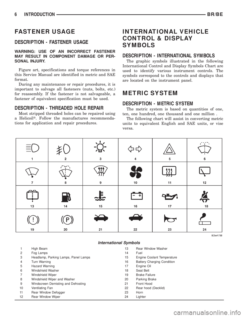
The graphic symbols illustrated in the following
International Control and Display Symbols Chart are
used to identify various instrument controls. The
symbols correspond to the controls and displays that
are located on the instrument panel.
METRIC SYSTEM
DESCRIPTION - METRIC SYSTEM
The metric system is based on quantities of one,
ten, one hundred, one thousand and one million .
The following chart will assist in converting metric
units to equivalent English and SAE units, or vise
versa.
International Symbols
1 High Beam 13 Rear Window Washer
2 Fog Lamps 14 Fuel
3 Headlamp, Parking Lamps, Panel Lamps 15 Engine Coolant Temperature
4 Turn Warning 16 Battery Charging Condition
5 Hazard Warning 17 Engine Oil
6 Windshield Washer 18 Seat Belt
7 Windshield Wiper 19 Brake Failure
8 Windshield Wiper and Washer 20 Parking Brake
9 Windscreen Demisting and Defrosting 21 Front Hood
10 Ventilating Fan 22 Rear hood (Decklid)
11 Rear Window Defogger 23 Horn
12 Rear Window Wiper 24 Lighter
6 INTRODUCTIONBR/BE
Page 12 of 2889
tification Number. The check digit is used by the
manufacturer and government agencies to verify the
authenticity of the vehicle and official documenta-
tion. The formula to use the check digit is not
released to the general public.
POSITION INTERPRETATION CODE = DESCRIPTION
1 Country of Origin 1 = United States
3 = Mexico
2 Make B = Dodge
3 Vehicle Type 6 = Incomplete
7 = Truck
4 Gross Vehicle Weight Rating H = 6001-7000
J = 7001-8000
K = 8001-9000
L = 9001-10,000
M = 10,001-14,000
5 Vehicle Line C = Ram Cab Chassis/Ram Pick Up (4x2)
F = Ram Cab Chassis/Ram Pick Up (4x4)
6 Series 1 = 1500
2 = 2500
3 = 3500
7 Body Style 2 = Club Cab
3 = Quad Cab
6 = Conventional Cab/Cab Chassis
8 Engine 6 = 5.9L 6 cyl. 24 Valve Diesel
7=5.9 6cyl. 24 Valve Turbo Diesel H/O
W = 8.0L 10 cyl. MPI
X = 3.9L 6 cyl. MPI
Y = 5.2L 8 cyl. MPI
Z = 5.9L 8 cyl. MPI-LDC
5 = 5.9L 8cyl. MPI-HDC
9 Check Digit 0 through 9 or X
10 Model Year 1=2001
11 Plant Location J = St. Louis North
S = Dodge City
M = Lago Alberto Assembly
12 thru 17 Vehicle Build Sequence
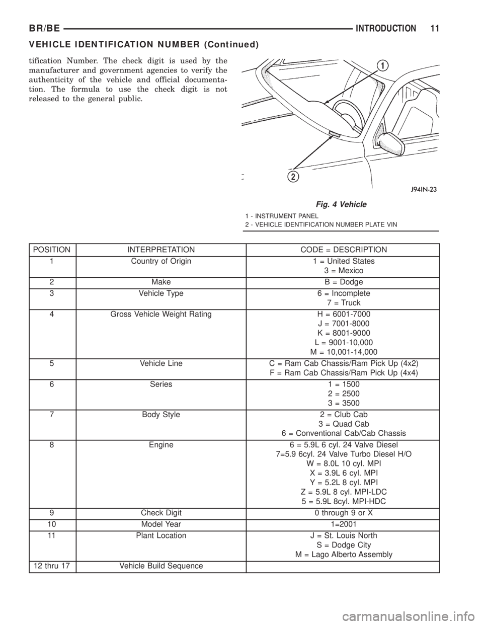
Fig. 4 Vehicle
1 - INSTRUMENT PANEL
2 - VEHICLE IDENTIFICATION NUMBER PLATE VIN
BR/BEINTRODUCTION 11
VEHICLE IDENTIFICATION NUMBER (Continued)
Page 307 of 2889
OPERATION - 2500/3500 WITH REAR DISC
BRAKES
To apply the parking brake the pedal is depressed.
This creates tension in the cable which pulls forward
on the park brake lever. The lever pushes the park
brake shoes outward and into contact with the drum
section of the rotor. The contact of shoe to rotor parks
the vehicle.
A torsion locking mechanism is used to hold the
pedal in an applied position. Parking brake release is
accomplished by the hand release.
A parking brake switch is mounted on the parking
brake lever and is actuated by movement of the
lever. The switch, which is in circuit with the red
warning light in the dash, will illuminate the warn-
ing light whenever the parking brake is applied.
Parking brake adjustment is controlled by a cable
tensioner mechanism. The cable tensioner, once
adjusted at the factory, should not need further
adjustment under normal circumstances. Adjustment
may be required if a new tensioner, or cables are
installed, or disconnected.
OPERATION - (1500 models) (Early 2500/3500
models with rear drum brakes)
To apply the parking brakes, the pedal is
depressed. This pulls the rear brake shoe actuating
levers forward. As the actuating lever is pulled for-
ward, the parking brake strut or cam, exerts a linear
force against the primary brake shoe. This action
presses the primary shoe into contact with the drum.
Once the primary shoe contacts the drum, force is
exerted through the strut/cam. This force is trans-
ferred through the strut/cam to the secondary brake
shoe causing it to pivot into the drum as well.
A torsion locking mechanism is used to hold the
pedal in an applied position. Parking brake release is
accomplished by the hand release.
A parking brake switch is mounted on the parking
brake lever and is actuated by movement of the
lever. The switch, which is in circuit with the red
warning light in the dash, will illuminate the warn-
ing light whenever the parking brake is applied.
Parking brake adjustment is controlled by a cable
tensioner mechanism. The cable tensioner, once
adjusted at the factory, should not need further
adjustment under normal circumstances. Adjustment
may be required if a new tensioner, or cables are
installed, or disconnected.
PEDAL
REMOVAL
(1) Release the parking brake.
(2) Raise the vehicle.(3) Loosen the cable tensioner nut at the equalizer
to create slack in the front cable.
(4) Lower the vehicle.
(5) Remove the knee bolster, (Refer to 23 - BODY/
INSTRUMENT PANEL/STEERING COLUMN
OPENING COVER - REMOVAL).
(6) Disconnect the brake lamp wire from the
switch on the pedal assembly.
(7) Roll the carpet back, loosen the front cable
grommet from the floorpan and the cable retainer.
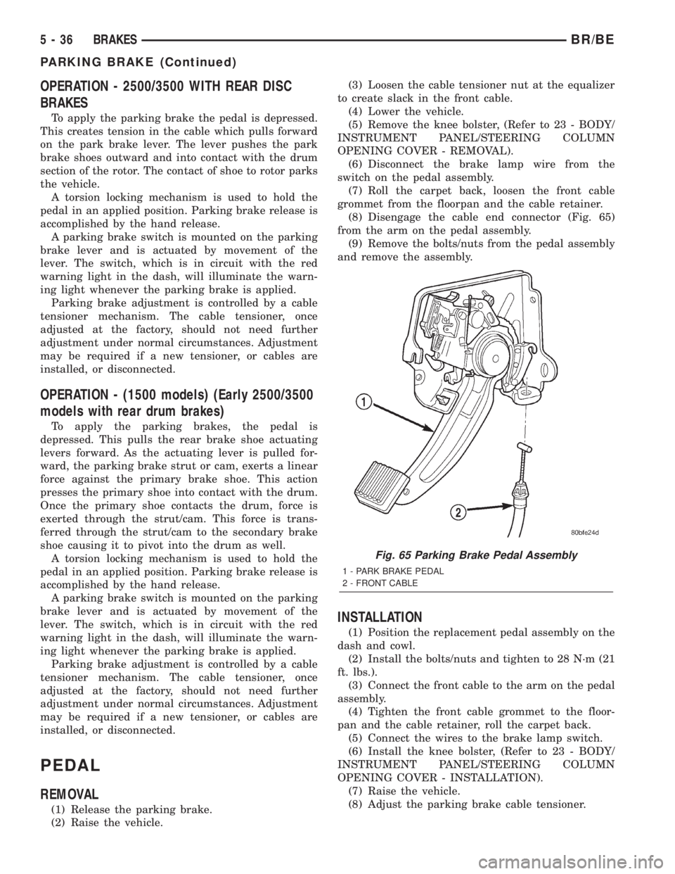
(8) Disengage the cable end connector (Fig. 65)
from the arm on the pedal assembly.
(9) Remove the bolts/nuts from the pedal assembly
and remove the assembly.
INSTALLATION
(1) Position the replacement pedal assembly on the
dash and cowl.
(2) Install the bolts/nuts and tighten to 28 N´m (21
ft. lbs.).
(3) Connect the front cable to the arm on the pedal
assembly.
(4) Tighten the front cable grommet to the floor-
pan and the cable retainer, roll the carpet back.
(5) Connect the wires to the brake lamp switch.
(6) Install the knee bolster, (Refer to 23 - BODY/
INSTRUMENT PANEL/STEERING COLUMN
OPENING COVER - INSTALLATION).
(7) Raise the vehicle.
(8) Adjust the parking brake cable tensioner.
Fig. 65 Parking Brake Pedal Assembly
1 - PARK BRAKE PEDAL
2 - FRONT CABLE
5 - 36 BRAKESBR/BE
PARKING BRAKE (Continued)
Page 311 of 2889
CABLE TENSIONER
ADJUSTMENT
NOTE: Tensioner adjustment is only necessary
when the tensioner, or a cable has been replaced or
disconnected for service. When adjustment is nec-
essary, perform adjustment only as described in the
following procedure. This is necessary to avoid
faulty park brake operation.
(1) Raise the vehicle.
(2) Back off the cable tensioner adjusting nut to
create slack in the cables.
(3) Remove the rear wheel/tire assemblies. Then
remove the brake drums.
(4) Verify the brakes are in good condition and
operating properly.
(5) Verify the park brake cables operate freely and
are not binding, or seized.
(6) Check the rear brake shoe adjustment with
standard brake gauge.
(7) Install the drums and verify that the drums
rotate freely without drag.
(8) Install the wheel/tire assemblies, (Refer to 22 -
TIRES/WHEELS/WHEELS - STANDARD PROCE-
DURE).
(9) Lower the vehicle enough for access to the park
brake foot pedal. Then fully apply the park brakes.
NOTE: Leave park brakes applied until adjustment
is complete.
(10) Raise the vehicle again.
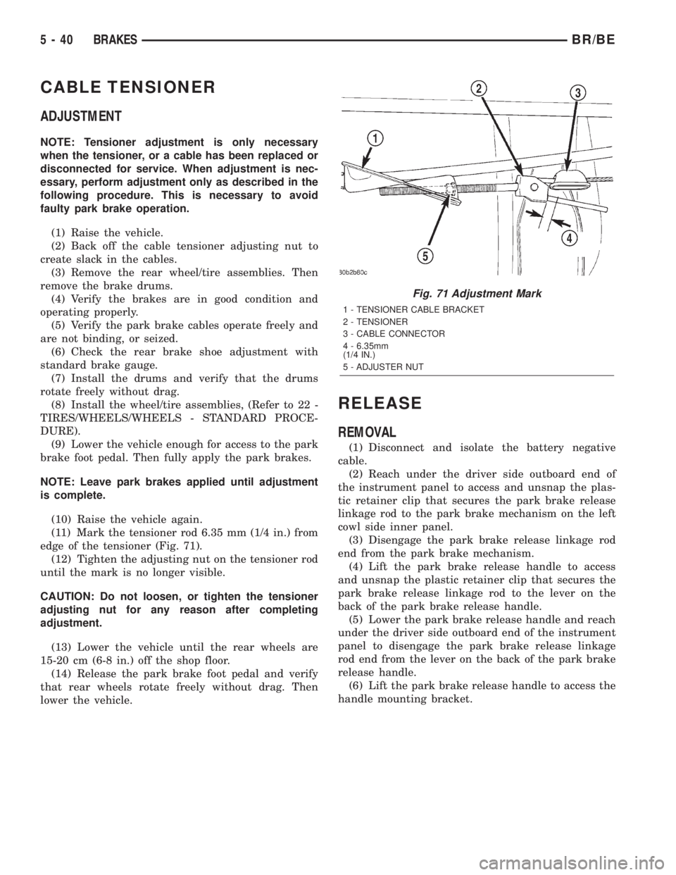
(11) Mark the tensioner rod 6.35 mm (1/4 in.) from
edge of the tensioner (Fig. 71).
(12) Tighten the adjusting nut on the tensioner rod
until the mark is no longer visible.
CAUTION: Do not loosen, or tighten the tensioner
adjusting nut for any reason after completing
adjustment.
(13) Lower the vehicle until the rear wheels are
15-20 cm (6-8 in.) off the shop floor.
(14) Release the park brake foot pedal and verify
that rear wheels rotate freely without drag. Then
lower the vehicle.
RELEASE
REMOVAL
(1) Disconnect and isolate the battery negative
cable.
(2) Reach under the driver side outboard end of
the instrument panel to access and unsnap the plas-
tic retainer clip that secures the park brake release
linkage rod to the park brake mechanism on the left
cowl side inner panel.
(3) Disengage the park brake release linkage rod
end from the park brake mechanism.
(4) Lift the park brake release handle to access
and unsnap the plastic retainer clip that secures the
park brake release linkage rod to the lever on the
back of the park brake release handle.
(5) Lower the park brake release handle and reach
under the driver side outboard end of the instrument
panel to disengage the park brake release linkage
rod end from the lever on the back of the park brake
release handle.
(6) Lift the park brake release handle to access the
handle mounting bracket.
Fig. 71 Adjustment Mark
1 - TENSIONER CABLE BRACKET
2 - TENSIONER
3 - CABLE CONNECTOR
4 - 6.35mm
(1/4 IN.)
5 - ADJUSTER NUT
5 - 40 BRAKESBR/BE
Page 312 of 2889
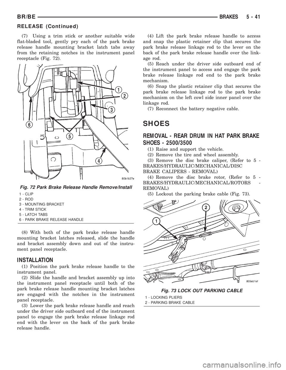
(7) Using a trim stick or another suitable wide
flat-bladed tool, gently pry each of the park brake
release handle mounting bracket latch tabs away
from the retaining notches in the instrument panel
receptacle (Fig. 72).
(8) With both of the park brake release handle
mounting bracket latches released, slide the handle
and bracket assembly down and out of the instru-
ment panel receptacle.
INSTALLATION
(1) Position the park brake release handle to the
instrument panel.
(2) Slide the handle and bracket assembly up into
the instrument panel receptacle until both of the
park brake release handle mounting bracket latches
are engaged with the notches in the instrument
panel receptacle.
(3) Lower the park brake release handle and reach
under the driver side outboard end of the instrument
panel to engage the park brake release linkage rod
end with the lever on the back of the park brake
release handle.(4) Lift the park brake release handle to access
and snap the plastic retainer clip that secures the
park brake release linkage rod to the lever on the
back of the park brake release handle over the link-
age rod.
(5) Reach under the driver side outboard end of
the instrument panel to access and engage the park
brake release linkage rod end to the park brake
mechanism.
(6) Snap the plastic retainer clip that secures the
park brake release linkage rod to the park brake
mechanism on the left cowl side inner panel over the
linkage rod.
(7) Reconnect the battery negative cable.
SHOES
REMOVAL - REAR DRUM IN HAT PARK BRAKE
SHOES - 2500/3500
(1) Raise and support the vehicle.
(2) Remove the tire and wheel assembly.
(3) Remove the disc brake caliper, (Refer to 5 -
BRAKES/HYDRAULIC/MECHANICAL/DISC
BRAKE CALIPERS - REMOVAL)
(4) Remove the disc brake rotor, (Refer to 5 -
BRAKES/HYDRAULIC/MECHANICAL/ROTORS -
REMOVAL)
(5) Lockout the parking brake cable (Fig. 73).
Fig. 72 Park Brake Release Handle Remove/Install
1 - CLIP
2 - ROD
3 - MOUNTING BRACKET
4 - TRIM STICK
5 - LATCH TABS
6 - PARK BRAKE RELEASE HANDLE
Fig. 73 LOCK OUT PARKING CABLE
1 - LOCKING PLIERS
2 - PARKING BRAKE CABLE
BR/BEBRAKES 5 - 41
RELEASE (Continued)
Page 332 of 2889
INSTALLATION
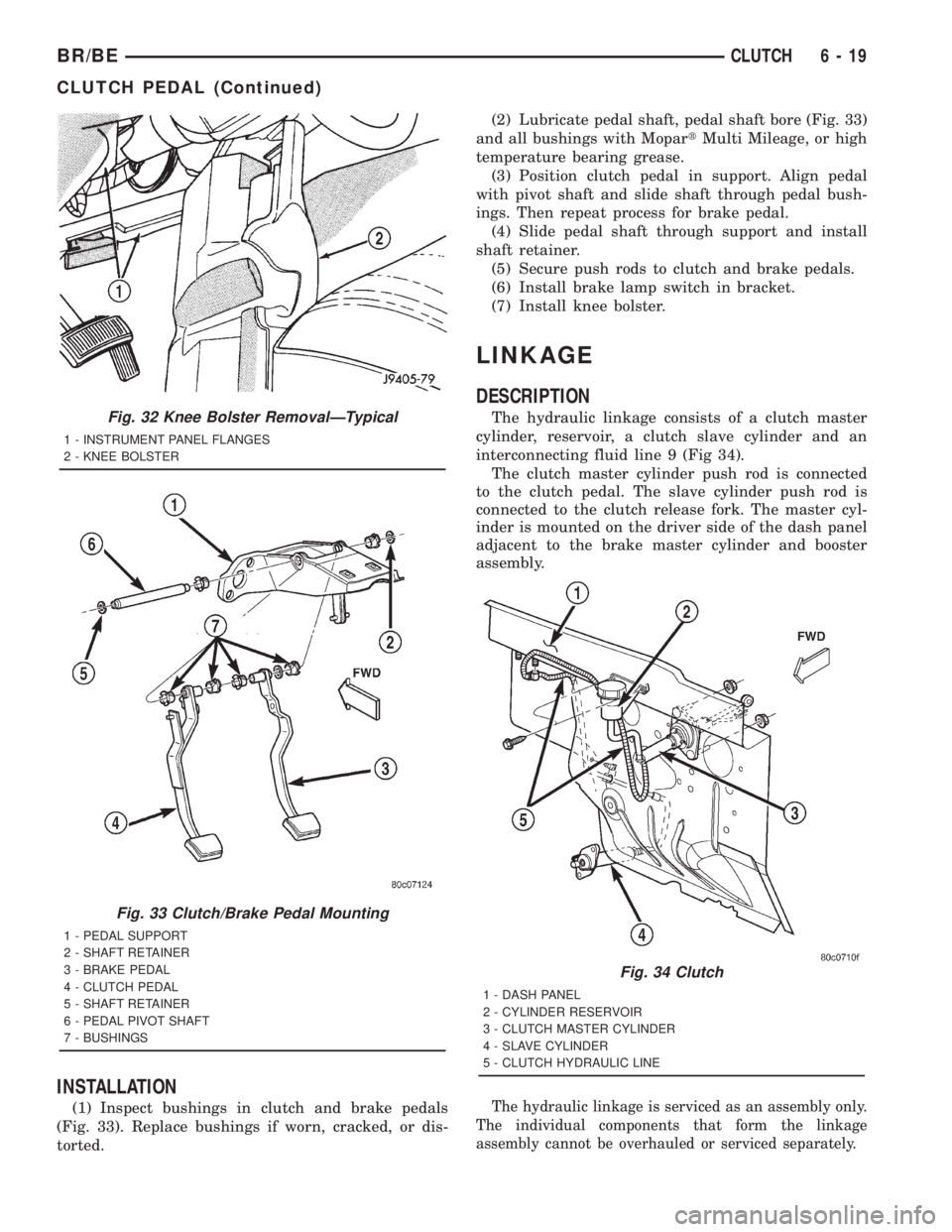
(1) Inspect bushings in clutch and brake pedals
(Fig. 33). Replace bushings if worn, cracked, or dis-
torted.(2) Lubricate pedal shaft, pedal shaft bore (Fig. 33)
and all bushings with MopartMulti Mileage, or high
temperature bearing grease.
(3) Position clutch pedal in support. Align pedal
with pivot shaft and slide shaft through pedal bush-
ings. Then repeat process for brake pedal.
(4) Slide pedal shaft through support and install
shaft retainer.
(5) Secure push rods to clutch and brake pedals.
(6) Install brake lamp switch in bracket.
(7) Install knee bolster.
LINKAGE
DESCRIPTION
The hydraulic linkage consists of a clutch master
cylinder, reservoir, a clutch slave cylinder and an
interconnecting fluid line 9 (Fig 34).
The clutch master cylinder push rod is connected
to the clutch pedal. The slave cylinder push rod is
connected to the clutch release fork. The master cyl-
inder is mounted on the driver side of the dash panel
adjacent to the brake master cylinder and booster
assembly.
The hydraulic linkage is serviced as an assembly only.
The individual components that form the linkage
assembly cannot be overhauled or serviced separately.
Fig. 32 Knee Bolster RemovalÐTypical
1 - INSTRUMENT PANEL FLANGES
2 - KNEE BOLSTER
Fig. 33 Clutch/Brake Pedal Mounting
1 - PEDAL SUPPORT
2 - SHAFT RETAINER
3 - BRAKE PEDAL
4 - CLUTCH PEDAL
5 - SHAFT RETAINER
6 - PEDAL PIVOT SHAFT
7 - BUSHINGS
Fig. 34 Clutch
1 - DASH PANEL
2 - CYLINDER RESERVOIR
3 - CLUTCH MASTER CYLINDER
4 - SLAVE CYLINDER
5 - CLUTCH HYDRAULIC LINE
BR/BECLUTCH 6 - 19
CLUTCH PEDAL (Continued)
Page 384 of 2889
ENGINE COOLANT
THERMOSTAT - 3.9L/5.2L/5.9L
DESCRIPTION
CAUTION: Do not operate an engine without a ther-
mostat, except for servicing or testing.
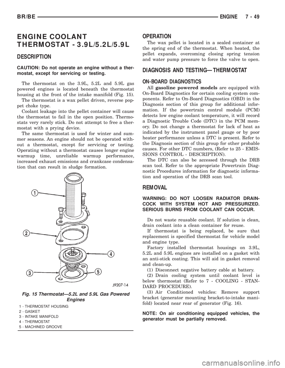
The thermostat on the 3.9L, 5.2L and 5.9L gas
powered engines is located beneath the thermostat
housing at the front of the intake manifold (Fig. 15).
The thermostat is a wax pellet driven, reverse pop-
pet choke type.
Coolant leakage into the pellet container will cause
the thermostat to fail in the open position. Thermo-
stats very rarely stick. Do not attempt to free a ther-
mostat with a prying device.
The same thermostat is used for winter and sum-
mer seasons. An engine should not be operated with-
out a thermostat, except for servicing or testing.
Operating without a thermostat causes longer engine
warmup time, unreliable warmup performance,
increased exhaust emissions and crankcase condensa-
tion that can result in sludge formation.
OPERATION
The wax pellet is located in a sealed container at
the spring end of the thermostat. When heated, the
pellet expands, overcoming closing spring tension
and water pump pressure to force the valve to open.
DIAGNOSIS AND TESTINGÐTHERMOSTAT
ON-BOARD DIAGNOSTICS
Allgasoline powered modelsare equipped with
On-Board Diagnostics for certain cooling system com-
ponents. Refer to On-Board Diagnostics (OBD) in the
Diagnosis section of this group for additional infor-
mation. If the powertrain control module (PCM)
detects low engine coolant temperature, it will record
a Diagnostic Trouble Code (DTC) in the PCM mem-
ory. Do not change a thermostat for lack of heat as
indicated by the instrument panel gauge or by poor
heater performance unless a DTC is present. Refer to
the Diagnosis section of this group for other probable
causes. For other DTC numbers, (Refer to 25 - EMIS-
SIONS CONTROL - DESCRIPTION).
The DTC can also be accessed through the DRB
scan tool. Refer to the appropriate Powertrain Diag-
nostic Procedures information for diagnostic informa-
tion and operation of the DRB scan tool.
REMOVAL
WARNING: DO NOT LOOSEN RADIATOR DRAIN-
COCK WITH SYSTEM HOT AND PRESSURIZED.
SERIOUS BURNS FROM COOLANT CAN OCCUR.
Do not waste reusable coolant. If solution is clean,
drain coolant into a clean container for reuse.
If thermostat is being replaced, be sure that
replacement is specified thermostat for vehicle model
and engine type.
Factory installed thermostat housings on 3.9L,
5.2L and 5.9L engines are installed on a gasket with
an anti-stick coating. This will aid in gasket removal
and clean-up.
(1) Disconnect negative battery cable at battery.
(2) Drain cooling system until coolant level is
below thermostat (Refer to 7 - COOLING - STAN-
DARD PROCEDURE).
(3) Air Conditioned vehicles: Remove support
bracket (generator mounting bracket-to-intake mani-
fold) located near rear of generator (Fig. 16).
NOTE: On air conditioning equipped vehicles, the
generator must be partially removed.
Fig. 15 ThermostatÐ5.2L and 5.9L Gas Powered
Engines
1 - THERMOSTAT HOUSING
2 - GASKET
3 - INTAKE MANIFOLD
4 - THERMOSTAT
5 - MACHINED GROOVE
BR/BEENGINE 7 - 49
Page 387 of 2889
ENGINE COOLANT
THERMOSTAT - 8.0L
DESCRIPTION
CAUTION: Do not operate an engine without a ther-
mostat, except for servicing or testing.
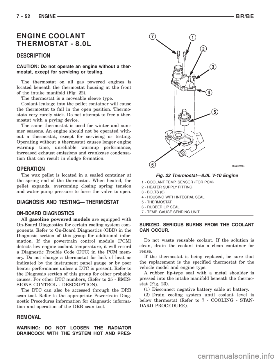
The thermostat on all gas powered engines is
located beneath the thermostat housing at the front
of the intake manifold (Fig. 22).
The thermostat is a moveable sleeve type.
Coolant leakage into the pellet container will cause
the thermostat to fail in the open position. Thermo-
stats very rarely stick. Do not attempt to free a ther-
mostat with a prying device.
The same thermostat is used for winter and sum-
mer seasons. An engine should not be operated with-
out a thermostat, except for servicing or testing.
Operating without a thermostat causes longer engine
warmup time, unreliable warmup performance,
increased exhaust emissions and crankcase condensa-
tion that can result in sludge formation.
OPERATION
The wax pellet is located in a sealed container at
the spring end of the thermostat. When heated, the
pellet expands, overcoming closing spring tension
and water pump pressure to force the valve to open.
DIAGNOSIS AND TESTINGÐTHERMOSTAT
ON-BOARD DIAGNOSTICS
Allgasoline powered modelsare equipped with
On-Board Diagnostics for certain cooling system com-
ponents. Refer to On-Board Diagnostics (OBD) in the
Diagnosis section of this group for additional infor-
mation. If the powertrain control module (PCM)
detects low engine coolant temperature, it will record
a Diagnostic Trouble Code (DTC) in the PCM mem-
ory. Do not change a thermostat for lack of heat as
indicated by the instrument panel gauge or by poor
heater performance unless a DTC is present. Refer to
the Diagnosis section of this group for other probable
causes. For other DTC numbers, (Refer to 25 - EMIS-
SIONS CONTROL - DESCRIPTION).
The DTC can also be accessed through the DRB
scan tool. Refer to the appropriate Powertrain Diag-
nostic Procedures information for diagnostic informa-
tion and operation of the DRB scan tool.
REMOVAL
WARNING: DO NOT LOOSEN THE RADIATOR
DRAINCOCK WITH THE SYSTEM HOT AND PRES-SURIZED. SERIOUS BURNS FROM THE COOLANT
CAN OCCUR.
Do not waste reusable coolant. If the solution is
clean, drain the coolant into a clean container for
reuse.
If the thermostat is being replaced, be sure that
the replacement is the specified thermostat for the
vehicle model and engine type.
A rubber lip-type seal with a metal shoulder is
pressed into the intake manifold beneath the thermo-
stat (Fig. 23).
(1) Disconnect negative battery cable at battery.
(2) Drain cooling system until coolant level is
below thermostat (Refer to 7 - COOLING - STAN-
DARD PROCEDURE).
Fig. 22 ThermostatÐ8.0L V-10 Engine
1 - COOLANT TEMP. SENSOR (FOR PCM)
2 - HEATER SUPPLY FITTING
3 - BOLTS (6)
4 - HOUSING WITH INTEGRAL SEAL
5 - THERMOSTAT
6 - RUBBER LIP SEAL
7 - TEMP. GAUGE SENDING UNIT
7 - 52 ENGINEBR/BE
Page 424 of 2889
AUDIO
TABLE OF CONTENTS
page page
AUDIO
DESCRIPTION............................1
OPERATION.............................2
DIAGNOSIS AND TESTING..................2
AUDIO................................2
SPECIAL TOOLS..........................4
ANTENNA BODY & CABLE
DESCRIPTION............................4
OPERATION.............................4
DIAGNOSIS AND TESTING..................5
ANTENNA.............................5
REMOVAL...............................6
INSTALLATION............................7
RADIO CHOKE RELAY
DESCRIPTION............................8
OPERATION.............................8
DIAGNOSIS AND TESTING..................8
RADIO CHOKE RELAY....................8
REMOVAL...............................9
INSTALLATION............................9
INSTRUMENT PANEL ANTENNA CABLE
REMOVAL...............................9
INSTALLATION...........................10
RADIO
DESCRIPTION...........................10
OPERATION.............................10
DIAGNOSIS AND TESTING.................10
RADIO...............................10
REMOVAL..............................11
INSTALLATION...........................12
RADIO NOISE SUPPRESSION COMPONENTS
DESCRIPTION...........................12
DIAGNOSIS AND TESTING.................12
RADIO NOISE SUPPRESSION
COMPONENTS.........................12ENGINE-TO-BODY GROUND STRAP
REMOVAL..............................13
INSTALLATION...........................13
CAB-TO- BED GROUND STRAP
REMOVAL..............................14
INSTALLATION...........................14
HEATER CORE GROUND STRAP
REMOVAL..............................14
INSTALLATION...........................15
REMOTE SWITCHES
DESCRIPTION...........................15
OPERATION.............................15
DIAGNOSIS AND TESTING.................16
REMOTE SWITCHES....................16
REMOVAL..............................16
INSTALLATION...........................17
SPEAKER
DESCRIPTION...........................17
OPERATION.............................17
DIAGNOSIS AND TESTING.................18
SPEAKER............................18
A-PILLAR TWEETER SPEAKER
REMOVAL..............................19
INSTALLATION...........................19
FRONT DOOR SPEAKER
REMOVAL..............................20
INSTALLATION...........................20
REAR CAB SIDE PANEL SPEAKER
REMOVAL..............................20
INSTALLATION...........................21
REAR DOOR SPEAKER
REMOVAL..............................21
INSTALLATION...........................21
AUDIO
DESCRIPTION
An audio system is standard factory-installed equip-
ment on this model, unless the vehicle is ordered with
an available radio delete option. The standard equip-
ment audio system includes an AM/FM/cassette (RAS
sales code) receiver, and speakers in four locations. Sev-
eral combinations of radio receivers and speaker systems
are offered as optional equipment on this model. The
audio system uses an ignition switched source of battery
current so that the system will only operate when theignition switch is in the On or Accessory positions. The
audio system includes the following components:
²Antenna
²Clockspring (with remote radio switches only)
²Filter, choke and speaker relay (with premium
speaker system only)
²High-line or premium Central Timer Module
(CTM) (with remote radio switches)
²Radio noise suppression components
²Radio receiver
²Remote radio switches (optional with RAZ radio
receiver only)
²Speakers
BR/BEAUDIO 8A - 1
Page 425 of 2889
Refer to Electrical, Restraints for more information
on the clockspring. Refer to Electrical, Body Control/
Central Control Module for more information on the
Central Timer Module. Refer to the appropriate wir-
ing information. The wiring information includes wir-
ing diagrams, proper wire and connector repair
procedures, details of wire harness routing and
retention, connector pin-out information and location
views for the various wire harness connectors, splices
and grounds. Following are general descriptions of
the remaining major components in the standard and
optional factory-installed audio systems.
OPERATION
See the owner's manual in the vehicle glove box for
more information on the features, use and operation
of each of the available audio systems.
CENTRAL TIMER MODULE
The high-line or premium Central Timer Module
(CTM) can also control some features of the audio
system when the vehicle is equipped with the
optional RAZ radio receiver and remote radio
switches. A high-line CTM is used on high-line ver-
sions of this vehicle. A premium CTM is used on
vehicles equipped with the optional heated seats. The
CTM combines the functions of a chime/buzzer mod-
ule, an intermittent wipe module, an illuminated
entry module, a remote keyless entry module, and a
vehicle theft security system module in a single unit.
The high-line or premium CTM also controls and
integrates many of the additional electronic functions
and features included on models with this option.The RAZ radio receiver with a remote radio switch
option is one of the features that the CTM controls.
The CTM is programmed to send switch status mes-
sages over the Chrysler Collision Detection (CCD)
data bus to control the volume, seek, and pre-set sta-
tion advance functions of the RAZ radio receiver. The
CTM monitors the status of the remote radio
switches located on the steering wheel through a
hard wired circuit. The CTM then sends the proper
switch status messages to the radio receiver. The
electronic circuitry within the radio receiver responds
to the switch status messages it receives by adjusting
the radio settings as requested.
Refer to Electrical, Body Control/Central Timer
Module for more information on the high-line CTM.
Refer to Remote Radio Switch in Description and
Operation for more information on this component.
In addition, radio receivers connected to the CCD
data bus have several audio system functions that
can be diagnosed using a DRBIIItscan tool. Refer to
the proper Diagnostic Procedures manual for more
information on DRBIIIttesting of the audio systems.
DIAGNOSIS AND TESTING - AUDIO
WARNING: ON VEHICLES EQUIPPED WITH AIR-
BAGS, REFER TO ELECTRICAL, RESTRAINTS
BEFORE ATTEMPTING ANY STEERING WHEEL,
STEERING COLUMN, OR INSTRUMENT PANEL
COMPONENT DIAGNOSIS OR SERVICE. FAILURE
TO TAKE THE PROPER PRECAUTIONS COULD
RESULT IN ACCIDENTAL AIRBAG DEPLOYMENT
AND POSSIBLE PERSONAL INJURY.
8A - 2 AUDIOBR/BE
AUDIO (Continued)