DODGE RAM 2001 Service Repair Manual
Manufacturer: DODGE, Model Year: 2001, Model line: RAM, Model: DODGE RAM 2001Pages: 2889, PDF Size: 68.07 MB
Page 2471 of 2889
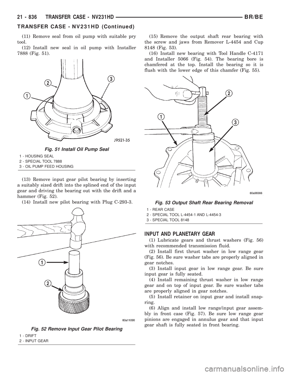
(11) Remove seal from oil pump with suitable pry
tool.
(12) Install new seal in oil pump with Installer
7888 (Fig. 51).
(13) Remove input gear pilot bearing by inserting
a suitably sized drift into the splined end of the input
gear and driving the bearing out with the drift and a
hammer (Fig. 52).
(14) Install new pilot bearing with Plug C-293-3.(15) Remove the output shaft rear bearing with
the screw and jaws from Remover L-4454 and Cup
8148 (Fig. 53).
(16) Install new bearing with Tool Handle C-4171
and Installer 5066 (Fig. 54). The bearing bore is
chamfered at the top. Install the bearing so it is
flush with the lower edge of this chamfer (Fig. 55).
INPUT AND PLANETARY GEAR
(1) Lubricate gears and thrust washers (Fig. 56)
with recommended transmission fluid.
(2) Install first thrust washer in low range gear
(Fig. 56). Be sure washer tabs are properly aligned in
gear notches.
(3) Install input gear in low range gear. Be sure
input gear is fully seated.
(4) Install remaining thrust washer in low range
gear and on top of input gear. Be sure washer tabs
are properly aligned in gear notches.
(5) Install retainer on input gear and install snap-
ring.
(6) Align and install low range/input gear assem-
bly in front case (Fig. 57). Be sure low range gear
pinions are engaged in annulus gear and that input
gear shaft is fully seated in front bearing.
Fig. 51 Install Oil Pump Seal
1 - HOUSING SEAL
2 - SPECIAL TOOL 7888
3 - OIL PUMP FEED HOUSING
Fig. 52 Remove Input Gear Pilot Bearing
1 - DRIFT
2 - INPUT GEAR
Fig. 53 Output Shaft Rear Bearing Removal
1 - REAR CASE
2 - SPECIAL TOOL L-4454-1 AND L-4454-3
3 - SPECIAL TOOL 8148
21 - 836 TRANSFER CASE - NV231HDBR/BE
TRANSFER CASE - NV231HD (Continued)
Page 2472 of 2889
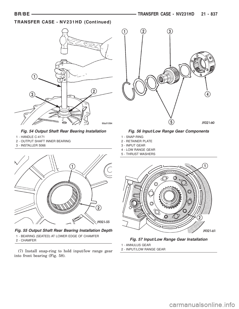
(7) Install snap-ring to hold input/low range gear
into front bearing (Fig. 58).
Fig. 54 Output Shaft Rear Bearing Installation
1 - HANDLE C-4171
2 - OUTPUT SHAFT INNER BEARING
3 - INSTALLER 5066
Fig. 55 Output Shaft Rear Bearing Installation Depth
1 - BEARING (SEATED) AT LOWER EDGE OF CHAMFER
2 - CHAMFER
Fig. 56 Input/Low Range Gear Components
1 - SNAP-RING
2 - RETAINER PLATE
3 - INPUT GEAR
4 - LOW RANGE GEAR
5 - THRUST WASHERS
Fig. 57 Input/Low Range Gear Installation
1 - ANNULUS GEAR
2 - INPUT/LOW RANGE GEAR
BR/BETRANSFER CASE - NV231HD 21 - 837
TRANSFER CASE - NV231HD (Continued)
Page 2473 of 2889
(8) Clean gasket sealer residue from retainer and
inspect retainer for cracks or other damage.
(9) Applya3mm(1/8 in.) bead of MopartGasket
Maker, or equivalent silicone adhesive, to sealing
surface of retainer.
(10) Align cavity in seal retainer with fluid return
hole in front of case.
CAUTION: Do not block fluid return cavity on seal-
ing surface of retainer when applying MoparTGas-
ket Maker, or equivalent silicone adhesive sealer.
Seal failure and fluid leak can result.
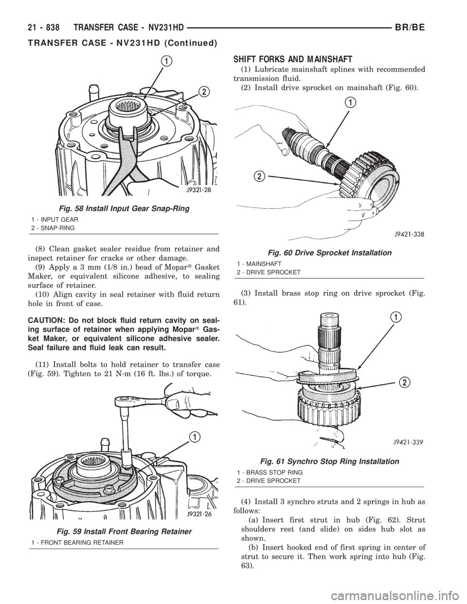
(11) Install bolts to hold retainer to transfer case
(Fig. 59). Tighten to 21 N´m (16 ft. lbs.) of torque.
SHIFT FORKS AND MAINSHAFT
(1) Lubricate mainshaft splines with recommended
transmission fluid.
(2) Install drive sprocket on mainshaft (Fig. 60).
(3) Install brass stop ring on drive sprocket (Fig.
61).
(4) Install 3 synchro struts and 2 springs in hub as
follows:
(a) Insert first strut in hub (Fig. 62). Strut
shoulders rest (and slide) on sides hub slot as
shown.
(b) Insert hooked end of first spring in center of
strut to secure it. Then work spring into hub (Fig.
63).
Fig. 58 Install Input Gear Snap-Ring
1 - INPUT GEAR
2 - SNAP-RING
Fig. 59 Install Front Bearing Retainer
1 - FRONT BEARING RETAINER
Fig. 60 Drive Sprocket Installation
1 - MAINSHAFT
2 - DRIVE SPROCKET
Fig. 61 Synchro Stop Ring Installation
1 - BRASS STOP RING
2 - DRIVE SPROCKET
21 - 838 TRANSFER CASE - NV231HDBR/BE
TRANSFER CASE - NV231HD (Continued)
Page 2474 of 2889
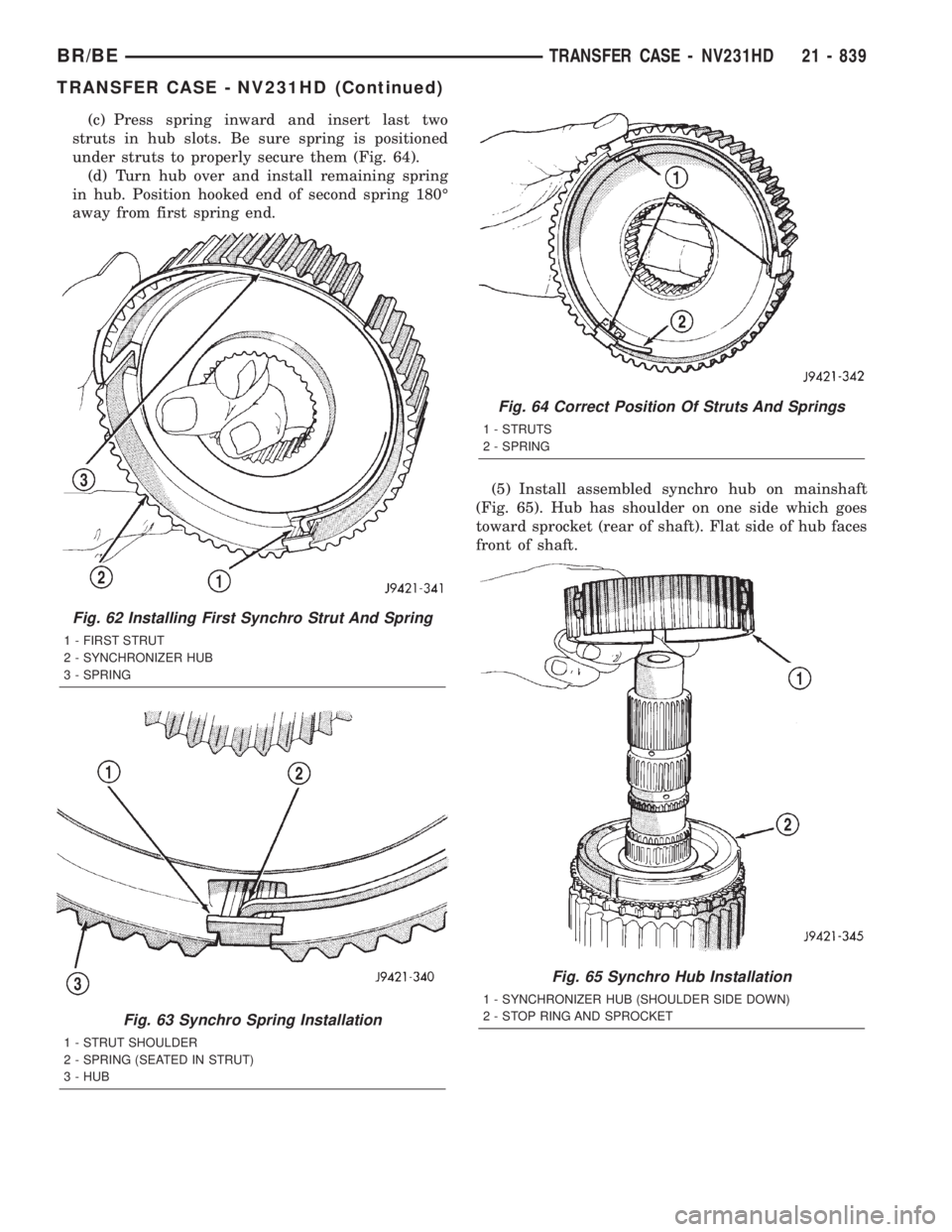
(c) Press spring inward and insert last two
struts in hub slots. Be sure spring is positioned
under struts to properly secure them (Fig. 64).
(d) Turn hub over and install remaining spring
in hub. Position hooked end of second spring 180É
away from first spring end.
(5) Install assembled synchro hub on mainshaft
(Fig. 65). Hub has shoulder on one side which goes
toward sprocket (rear of shaft). Flat side of hub faces
front of shaft.
Fig. 62 Installing First Synchro Strut And Spring
1 - FIRST STRUT
2 - SYNCHRONIZER HUB
3 - SPRING
Fig. 63 Synchro Spring Installation
1 - STRUT SHOULDER
2 - SPRING (SEATED IN STRUT)
3 - HUB
Fig. 64 Correct Position Of Struts And Springs
1 - STRUTS
2 - SPRING
Fig. 65 Synchro Hub Installation
1 - SYNCHRONIZER HUB (SHOULDER SIDE DOWN)
2 - STOP RING AND SPROCKET
BR/BETRANSFER CASE - NV231HD 21 - 839
TRANSFER CASE - NV231HD (Continued)
Page 2475 of 2889
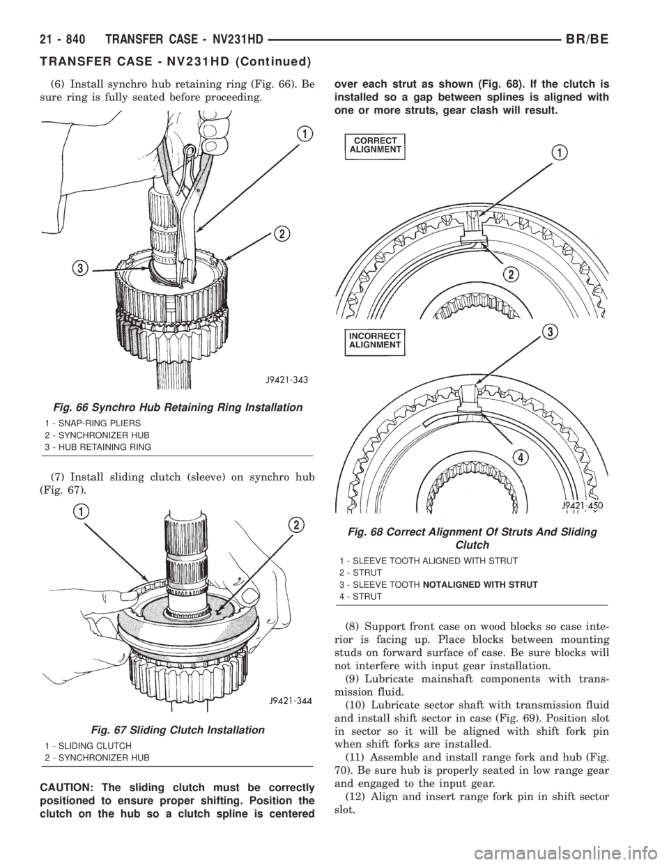
(6) Install synchro hub retaining ring (Fig. 66). Be
sure ring is fully seated before proceeding.
(7) Install sliding clutch (sleeve) on synchro hub
(Fig. 67).
CAUTION: The sliding clutch must be correctly
positioned to ensure proper shifting. Position the
clutch on the hub so a clutch spline is centeredover each strut as shown (Fig. 68). If the clutch is
installed so a gap between splines is aligned with
one or more struts, gear clash will result.
(8) Support front case on wood blocks so case inte-
rior is facing up. Place blocks between mounting
studs on forward surface of case. Be sure blocks will
not interfere with input gear installation.
(9) Lubricate mainshaft components with trans-
mission fluid.
(10) Lubricate sector shaft with transmission fluid
and install shift sector in case (Fig. 69). Position slot
in sector so it will be aligned with shift fork pin
when shift forks are installed.
(11) Assemble and install range fork and hub (Fig.
70). Be sure hub is properly seated in low range gear
and engaged to the input gear.
(12) Align and insert range fork pin in shift sector
slot.
Fig. 66 Synchro Hub Retaining Ring Installation
1 - SNAP-RING PLIERS
2 - SYNCHRONIZER HUB
3 - HUB RETAINING RING
Fig. 67 Sliding Clutch Installation
1 - SLIDING CLUTCH
2 - SYNCHRONIZER HUB
Fig. 68 Correct Alignment Of Struts And Sliding
Clutch
1 - SLEEVE TOOTH ALIGNED WITH STRUT
2 - STRUT
3 - SLEEVE TOOTHNOTALIGNED WITH STRUT
4 - STRUT
21 - 840 TRANSFER CASE - NV231HDBR/BE
TRANSFER CASE - NV231HD (Continued)
Page 2476 of 2889
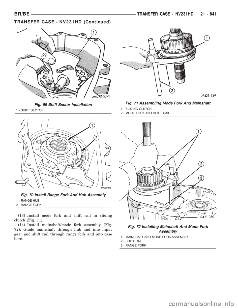
(13) Install mode fork and shift rail in sliding
clutch (Fig. 71).
(14) Install mainshaft/mode fork assembly (Fig.
72). Guide mainshaft through hub and into input
gear and shift rail through range fork and into case
bore.
Fig. 69 Shift Sector Installation
1 - SHIFT SECTOR
Fig. 70 Install Range Fork And Hub Assembly
1 - RANGE HUB
2 - RANGE FORK
Fig. 71 Assembling Mode Fork And Mainshaft
1 - SLIDING CLUTCH
2 - MODE FORK AND SHIFT RAIL
Fig. 72 Installing Mainshaft And Mode Fork
Assembly
1 - MAINSHAFT AND MODE FORK ASSEMBLY
2 - SHIFT RAIL
3 - RANGE FORK
BR/BETRANSFER CASE - NV231HD 21 - 841
TRANSFER CASE - NV231HD (Continued)
Page 2477 of 2889
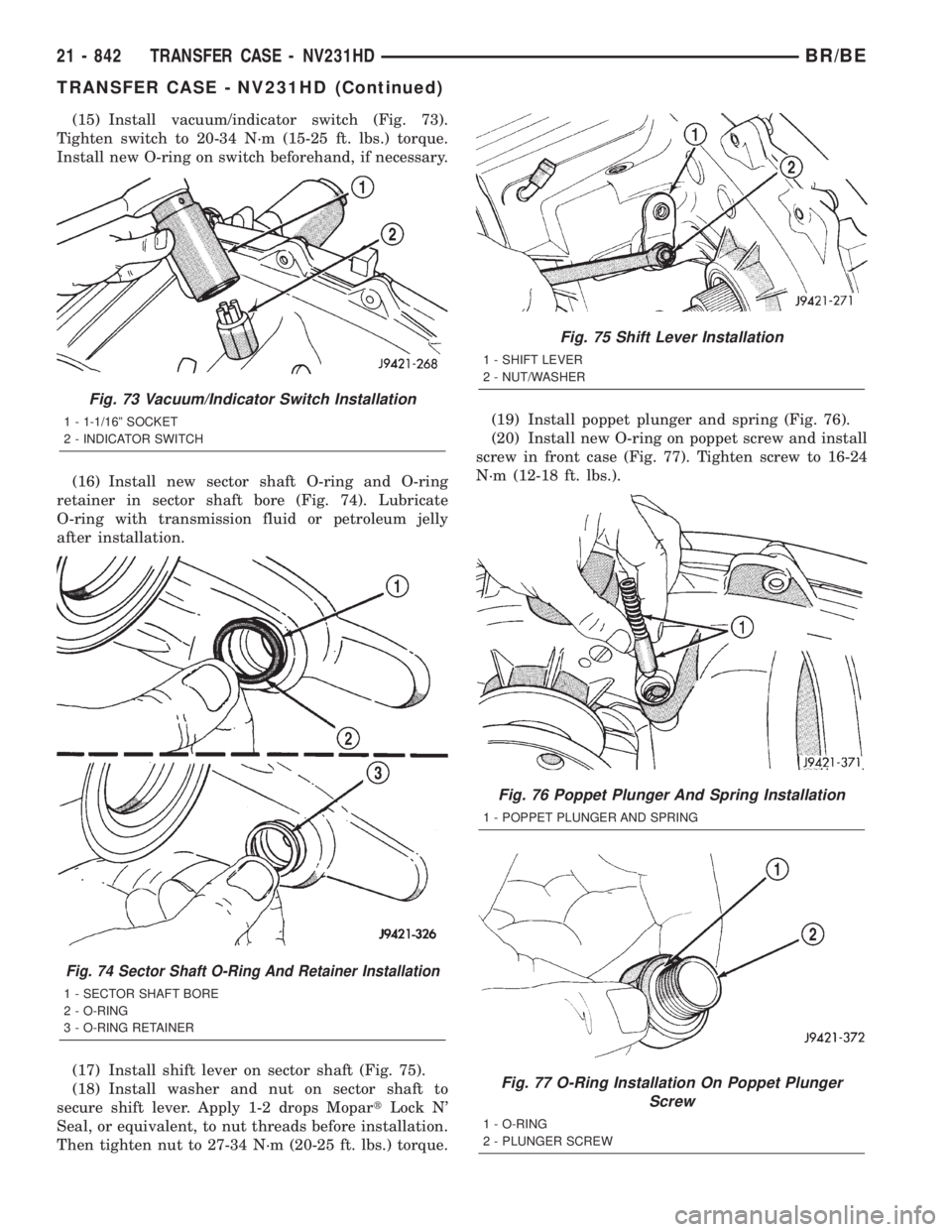
(15) Install vacuum/indicator switch (Fig. 73).
Tighten switch to 20-34 N´m (15-25 ft. lbs.) torque.
Install new O-ring on switch beforehand, if necessary.
(16) Install new sector shaft O-ring and O-ring
retainer in sector shaft bore (Fig. 74). Lubricate
O-ring with transmission fluid or petroleum jelly
after installation.
(17) Install shift lever on sector shaft (Fig. 75).
(18) Install washer and nut on sector shaft to
secure shift lever. Apply 1-2 drops MopartLock N'
Seal, or equivalent, to nut threads before installation.
Then tighten nut to 27-34 N´m (20-25 ft. lbs.) torque.(19) Install poppet plunger and spring (Fig. 76).
(20) Install new O-ring on poppet screw and install
screw in front case (Fig. 77). Tighten screw to 16-24
N´m (12-18 ft. lbs.).
Fig. 73 Vacuum/Indicator Switch Installation
1 - 1-1/16º SOCKET
2 - INDICATOR SWITCH
Fig. 74 Sector Shaft O-Ring And Retainer Installation
1 - SECTOR SHAFT BORE
2 - O-RING
3 - O-RING RETAINER
Fig. 75 Shift Lever Installation
1 - SHIFT LEVER
2 - NUT/WASHER
Fig. 76 Poppet Plunger And Spring Installation
1 - POPPET PLUNGER AND SPRING
Fig. 77 O-Ring Installation On Poppet Plunger
Screw
1 - O-RING
2 - PLUNGER SCREW
21 - 842 TRANSFER CASE - NV231HDBR/BE
TRANSFER CASE - NV231HD (Continued)
Page 2478 of 2889
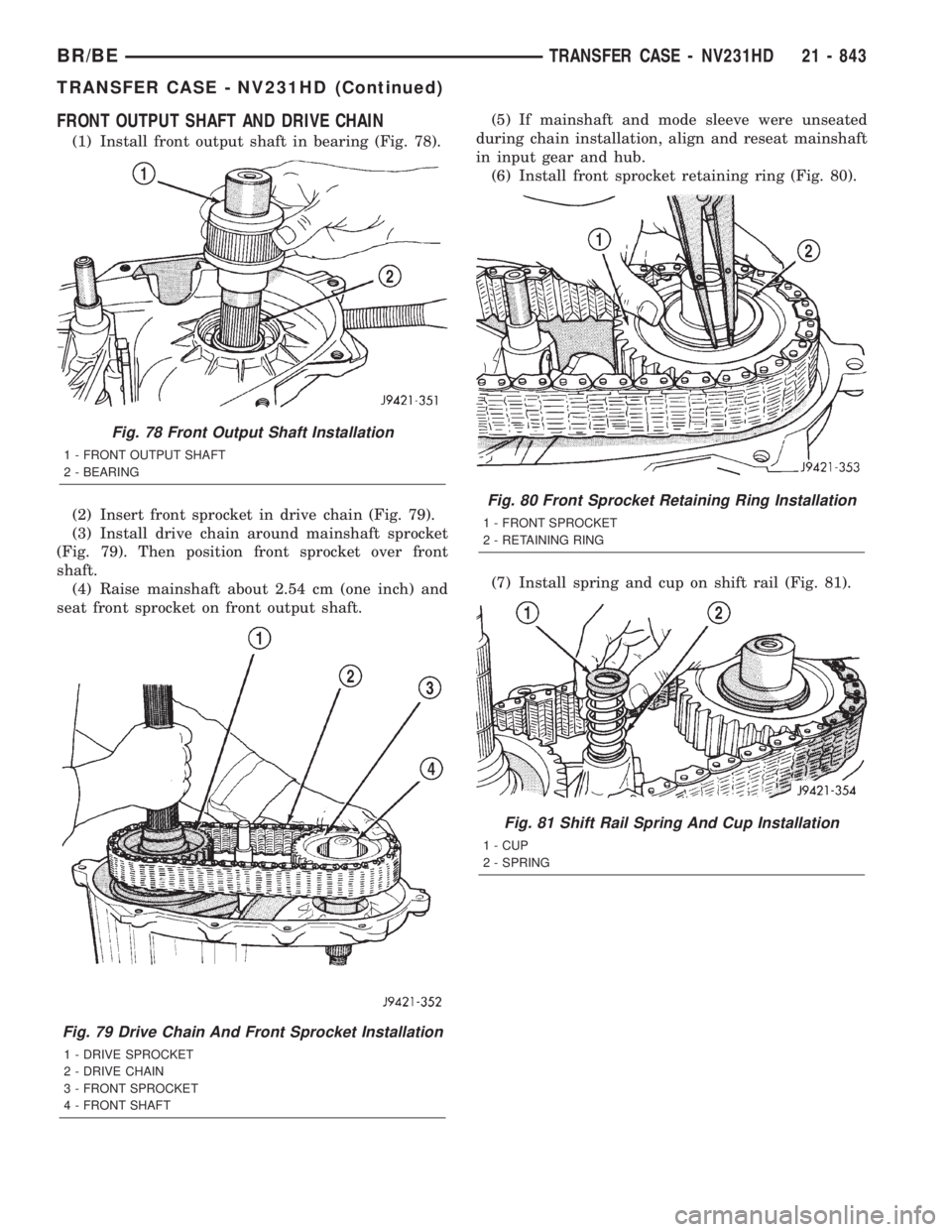
FRONT OUTPUT SHAFT AND DRIVE CHAIN
(1) Install front output shaft in bearing (Fig. 78).
(2) Insert front sprocket in drive chain (Fig. 79).
(3) Install drive chain around mainshaft sprocket
(Fig. 79). Then position front sprocket over front
shaft.
(4) Raise mainshaft about 2.54 cm (one inch) and
seat front sprocket on front output shaft.(5) If mainshaft and mode sleeve were unseated
during chain installation, align and reseat mainshaft
in input gear and hub.
(6) Install front sprocket retaining ring (Fig. 80).
(7) Install spring and cup on shift rail (Fig. 81).
Fig. 78 Front Output Shaft Installation
1 - FRONT OUTPUT SHAFT
2 - BEARING
Fig. 79 Drive Chain And Front Sprocket Installation
1 - DRIVE SPROCKET
2 - DRIVE CHAIN
3 - FRONT SPROCKET
4 - FRONT SHAFT
Fig. 80 Front Sprocket Retaining Ring Installation
1 - FRONT SPROCKET
2 - RETAINING RING
Fig. 81 Shift Rail Spring And Cup Installation
1 - CUP
2 - SPRING
BR/BETRANSFER CASE - NV231HD 21 - 843
TRANSFER CASE - NV231HD (Continued)
Page 2479 of 2889
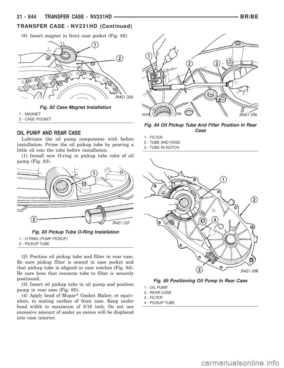
(8) Insert magnet in front case pocket (Fig. 82).
OIL PUMP AND REAR CASE
Lubricate the oil pump components with before
installation. Prime the oil pickup tube by pouring a
little oil into the tube before installation.
(1) Install new O-ring in pickup tube inlet of oil
pump (Fig. 83).
(2) Position oil pickup tube and filter in rear case.
Be sure pickup filter is seated in case pocket and
that pickup tube is aligned in case notches (Fig. 84).
Be sure hose that connects tube to filter is securely
positioned.
(3) Insert oil pickup tube in oil pump and position
pump in rear case (Fig. 85).
(4) Apply bead of MopartGasket Maker, or equiv-
alent, to mating surface of front case. Keep sealer
bead width to maximum of 3/16 inch. Do not use
excessive amount of sealer as excess will be displaced
into case interior.
Fig. 82 Case Magnet Installation
1 - MAGNET
2 - CASE POCKET
Fig. 83 Pickup Tube O-Ring Installation
1 - O-RING (PUMP PICKUP)
2 - PICKUP TUBE
Fig. 84 Oil Pickup Tube And Filter Position In Rear
Case
1 - FILTER
2 - TUBE AND HOSE
3 - TUBE IN NOTCH
Fig. 85 Positioning Oil Pump In Rear Case
1 - OIL PUMP
2 - REAR CASE
3 - FILTER
4 - PICKUP TUBE
21 - 844 TRANSFER CASE - NV231HDBR/BE
TRANSFER CASE - NV231HD (Continued)
Page 2480 of 2889
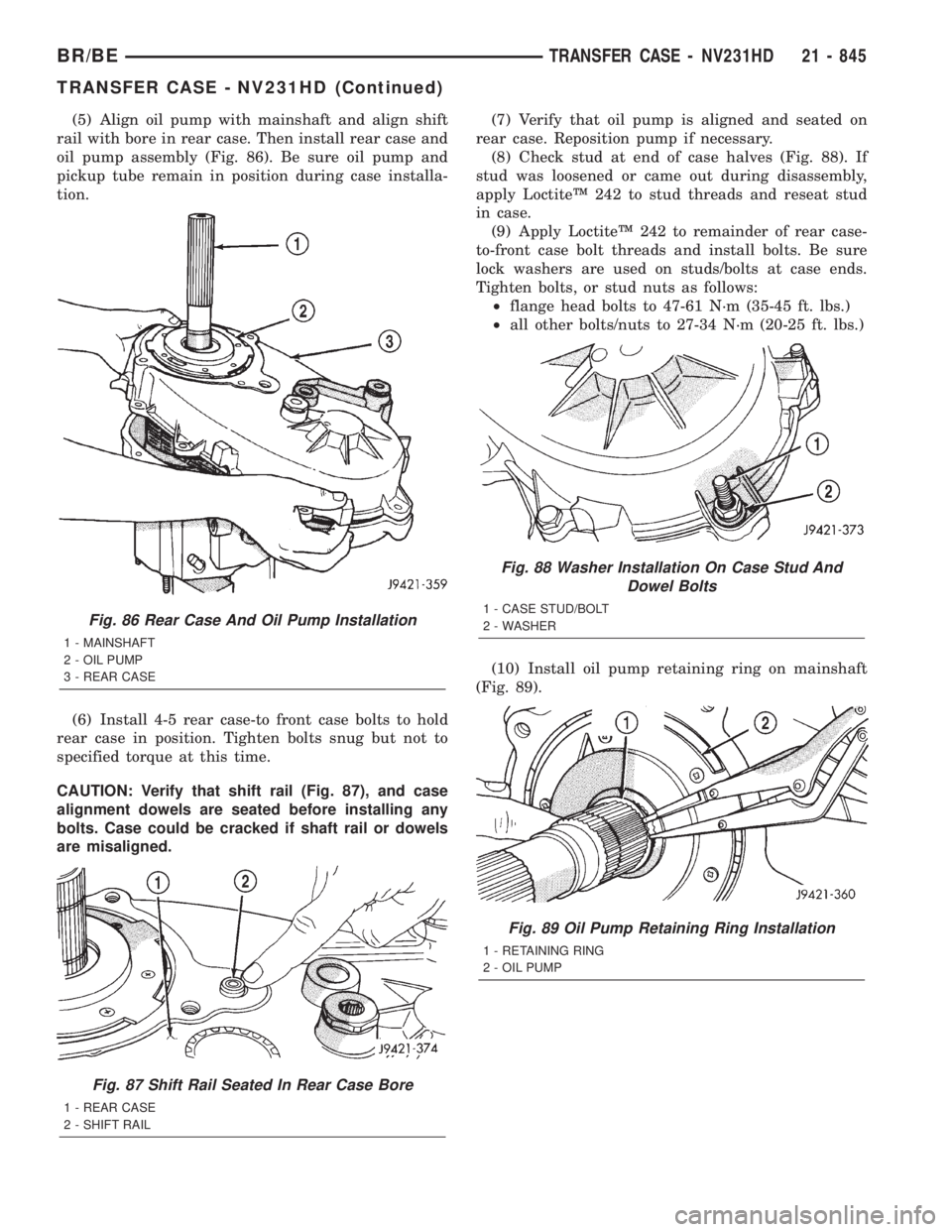
(5) Align oil pump with mainshaft and align shift
rail with bore in rear case. Then install rear case and
oil pump assembly (Fig. 86). Be sure oil pump and
pickup tube remain in position during case installa-
tion.
(6) Install 4-5 rear case-to front case bolts to hold
rear case in position. Tighten bolts snug but not to
specified torque at this time.
CAUTION: Verify that shift rail (Fig. 87), and case
alignment dowels are seated before installing any
bolts. Case could be cracked if shaft rail or dowels
are misaligned.(7) Verify that oil pump is aligned and seated on
rear case. Reposition pump if necessary.
(8) Check stud at end of case halves (Fig. 88). If
stud was loosened or came out during disassembly,
apply LoctiteŸ 242 to stud threads and reseat stud
in case.
(9) Apply LoctiteŸ 242 to remainder of rear case-
to-front case bolt threads and install bolts. Be sure
lock washers are used on studs/bolts at case ends.
Tighten bolts, or stud nuts as follows:
²flange head bolts to 47-61 N´m (35-45 ft. lbs.)
²all other bolts/nuts to 27-34 N´m (20-25 ft. lbs.)
(10) Install oil pump retaining ring on mainshaft
(Fig. 89).
Fig. 86 Rear Case And Oil Pump Installation
1 - MAINSHAFT
2 - OIL PUMP
3 - REAR CASE
Fig. 87 Shift Rail Seated In Rear Case Bore
1 - REAR CASE
2 - SHIFT RAIL
Fig. 88 Washer Installation On Case Stud And
Dowel Bolts
1 - CASE STUD/BOLT
2 - WASHER
Fig. 89 Oil Pump Retaining Ring Installation
1 - RETAINING RING
2 - OIL PUMP
BR/BETRANSFER CASE - NV231HD 21 - 845
TRANSFER CASE - NV231HD (Continued)