DODGE RAM 2001 Service Repair Manual
Manufacturer: DODGE, Model Year: 2001, Model line: RAM, Model: DODGE RAM 2001Pages: 2889, PDF Size: 68.07 MB
Page 2491 of 2889
case. The switch is operated by the transfer case
range rod.
SHIFT MECHANISM
The transfer case is operated by an adjustable floor
mounted shift linkage. The transfer case shift lever
is directly attached to the shift sector. The sector
operates the range and mode forks within the trans-
fer case.
A straight line shift pattern is used with a NEU-
TRAL detent. Lever range positions are imprinted in
the shift knob.
SHIFTING
The synchronizer components allow the transfer
case to be shifted between the 2H and 4H operating
ranges while the vehicle is in motion. The vehiclemust have the transmission placed in NEUTRAL, or
the clutch depressed in the case of a manual trans-
mission, and be moving less than 2-3 MPH when
shifting into the 4L operating range.
DIAGNOSIS AND TESTING - TRANSFER CASE
Before beginning repair on a suspected transfer
case malfunction, check all other driveline compo-
nents beforehand.
The actual cause of a problem may be related to
such items as: front hubs, axles, propeller shafts,
wheels and tires, transmission, or clutch instead. If
all other driveline components are in good condition
and operating properly, refer to the Diagnosis Chart
for further information.
21 - 856 TRANSFER CASE - NV241LDBR/BE
TRANSFER CASE - NV241LD (Continued)
Page 2492 of 2889
DIAGNOSIS CHART
Condition Possible Cause Correction
Transfer Case difficult to shift or will
not shift into desired range.1) Vehicle speed too great to permit
shifting.1) Stop vehicle and shift into desired
range. Or, reduce speed to below 3-4
km/h (2-3 mph) before attempting the
shift.
2) If vehicle was operated for an
extended period in 4H on a dry paved
surface, the driveline torque load may
be causing a bind.2) Stop vehicle and shift the
transmission into neutral. Shift the
transfer case to 2H and operate
vehicle in 2H on dry paved surfaces.
3) Transfer case external shift linkage
binding.3) Lubricate, repair, or replace linkage
bushings, or tighten loose
components as necessary.
4) Insufficient or incorrect lubricant. 4) Drain and refill to edge of fill hole
with MoparTATF +4, type 9602,
Automatic Transmission fluid.
5) Internal components binding, worn,
or damaged.5) Disassemble the transfer case and
replace worn or damaged
components as necessary.
Transfer Case noisy in all operating
ranges.1) Insufficient or incorrect lubricant. 1) Drain and refill to edge of fill hole
with MoparTATF +4, type 9602,
Automatic Transmission fluid.
Noisy in, or jumps out of, four wheel
drive low range.1) Transfer case not completely
engaged in 4L position.1) With the transmission in
NEUTRAL, or the clutch depressed in
the case of a manual transmission
and the vehicle moving under 3-4
km/h (2-3 mph), shift the transfer case
to NEUTRAL and then shift into the
4L position.
2) Shift linkage out of adjustment. 2) Adjust linkage.
3) Shift linkage loose or binding. 3) Tighten, lubricate, or repair linkage
as necessary.
4) Range fork damaged, inserts worn,
or fork is binding on the shift rail.4) Disassemble unit and repair as
necessary.
5) Low range gear worn or damaged. 5) Disassemble unit and repair as
necessary.
Lubricant leaking from output shaft
seal or vent.1) Transfer case overfilled. 1) Drain lubricant to the correct level.
2) Vent closed or restricted. 2) Clear or replace vent as necessary.
3) Output shaft seals damaged or
installed incorrectly.3) Replace seal as necessary. Check
to ensure that another component, the
propeller shaft slip yoke for example,
is not causing damage to seal.
Abnormal tire wear. 1) Extended operation on hard, dry
surfaces in the 4H position.1) Operate vehicle in the 2H position
on hard, dry surfaces.
BR/BETRANSFER CASE - NV241LD 21 - 857
TRANSFER CASE - NV241LD (Continued)
Page 2493 of 2889
REMOVAL
(1) Raise and support vehicle.
(2) Remove skid plate, if equipped. (Refer to 13 -
FRAMES & BUMPERS/FRAME/TRANSFER CASE
SKID PLATE - REMOVAL)
(3) Position drain oil container under transfer
case.
(4) Remove transfer case drain plug and drain
lubricant into container.
(5) Disconnect vent hose and vacuum harness at
transfer case switch.
(6) Disconnect shift rod from grommet in transfer
case shift lever, or from floor shift arm whichever
provides easy access. Use channel lock style pliers to
press rod out of lever grommet.
(7) Support transmission with jack stand.
(8) Remove rear crossmember.
(9) Mark front and rear propeller shafts for assem-
bly reference.
(10) Remove front and rear propeller shafts. (Refer
to 3 - DIFFERENTIAL & DRIVELINE/PROPELLER
SHAFT/PROPELLER SHAFT - REMOVAL)
(11) Support transfer case with suitable jack.
Secure transfer case to jack with safety chains.
(12) Remove nuts attaching transfer case to trans-
mission.
(13) Move transfer case assembly rearward until
free of transmission output shaft.
(14) Lower jack and move transfer case from
under vehicle.
DISASSEMBLY
Position transfer case in a shallow drain pan.
Remove drain plug and drain any remaining lubri-
cant remaining in case.
REAR EXTENSION, RETAINER, AND REAR CASE
(1) Remove rear extension bolts (Fig. 2).(2) Remove rear extension housing (Fig. 3). Tap
extension once or twice with a plastic mallet to break
sealer bead and loosen it.
(3) Remove output bearing retaining ring with
heavy duty snap-ring pliers (Fig. 4).
Fig. 2 Rear Extension Bolt Removal
1 - SOCKET
2 - REAR EXTENSION
Fig. 3 Rear Extension Housing Removal
1 - SEAL
2 - REAR EXTENSION HOUSING
3 - REAR RETAINER
Fig. 4 Removing Output Bearing Retaining Ring
1 - OUTPUT BEARING
2 - RETAINING RING
3 - REAR RETAINER
21 - 858 TRANSFER CASE - NV241LDBR/BE
TRANSFER CASE - NV241LD (Continued)
Page 2494 of 2889
(4) Remove rear retainer bolts (Fig. 5).
(5) Loosen rear retainer with pry bar placed under
flange (Fig. 6).
(6) Remove rear retainer and output bearing as
assembly (Fig. 7).
COMPANION FLANGE AND SHIFT LEVER
(1) Shift transfer case into NEUTRAL.
(2) Remove companion flange nut (Fig. 8). Discard
nut after removal. It is not reusable.
(3) Remove companion flange from front output
shaft. Use a suitable puller if flange can not be
removed by hand.
(4) Remove companion flange rubber seal from
front output shaft (Fig. 9).
(5) Remove nut and washer that retain shift lever
to sector shaft. Then remove shift lever from shaft
(Fig. 10).
FRONT OUTPUT SHAFT AND DRIVE CHAIN
(1) Remove output bearing retaining ring with
heavy duty snap-ring pliers.
(2) Remove output shaft bearing.
Fig. 5 Removing Rear Extension Bolts
1 - SOCKET
2 - REAR RETAINER
Fig. 6 Loosening Rear Retainer
1 - REAR RETAINER
2 - FLANGE
3-PRYTOOL
Fig. 7 Rear Retainer Removal
1 - OUTPUT BEARING
2 - REAR RETAINER
Fig. 8 Removing Companion Flange Nut
1 - COMPANION FLANGE
2 - SOCKET
Fig. 9 Companion Flange Seal Removal
1 - FLANGE SEAL
BR/BETRANSFER CASE - NV241LD 21 - 859
TRANSFER CASE - NV241LD (Continued)
Page 2495 of 2889
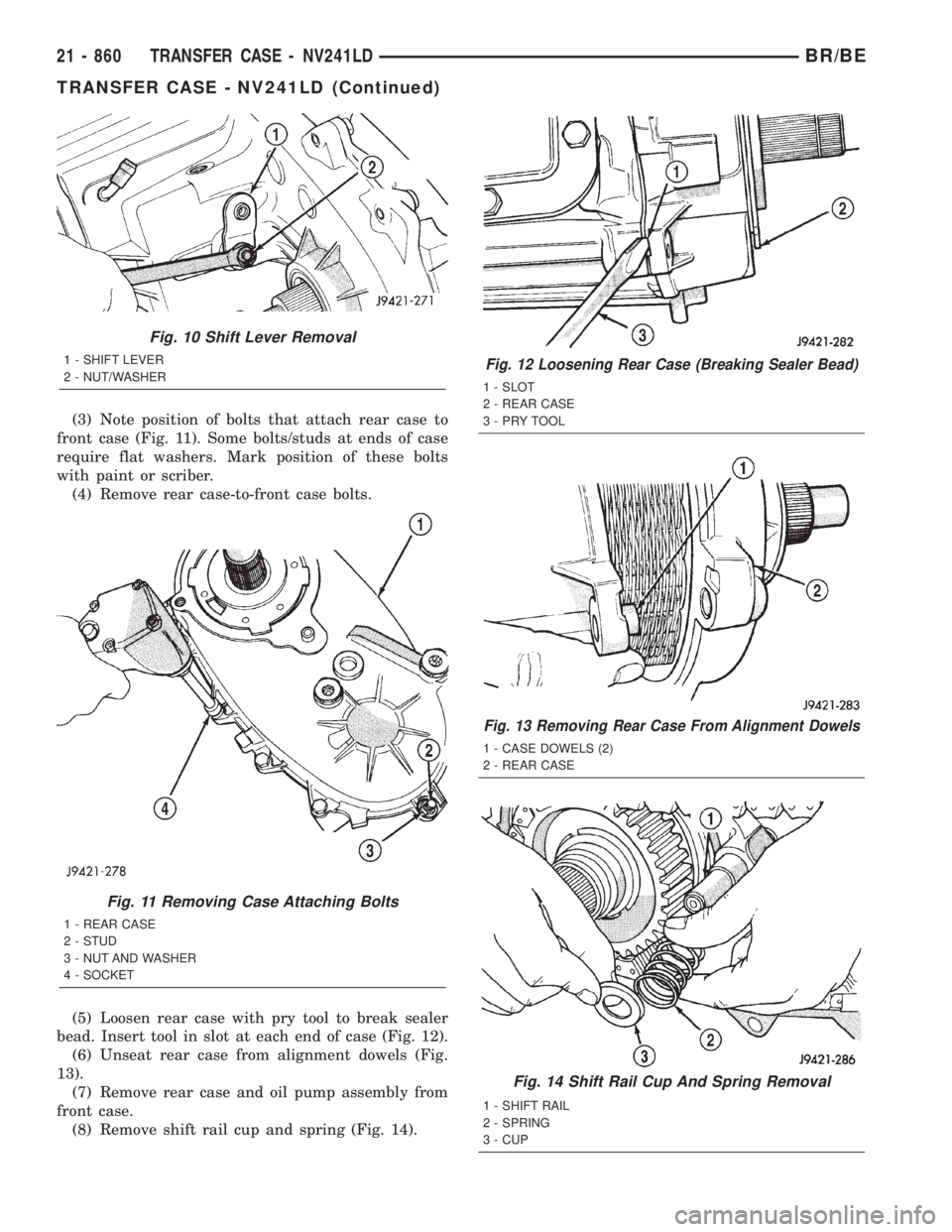
(3) Note position of bolts that attach rear case to
front case (Fig. 11). Some bolts/studs at ends of case
require flat washers. Mark position of these bolts
with paint or scriber.
(4) Remove rear case-to-front case bolts.
(5) Loosen rear case with pry tool to break sealer
bead. Insert tool in slot at each end of case (Fig. 12).
(6) Unseat rear case from alignment dowels (Fig.
13).
(7) Remove rear case and oil pump assembly from
front case.
(8) Remove shift rail cup and spring (Fig. 14).
Fig. 10 Shift Lever Removal
1 - SHIFT LEVER
2 - NUT/WASHER
Fig. 11 Removing Case Attaching Bolts
1 - REAR CASE
2 - STUD
3 - NUT AND WASHER
4 - SOCKET
Fig. 12 Loosening Rear Case (Breaking Sealer Bead)
1 - SLOT
2 - REAR CASE
3-PRYTOOL
Fig. 13 Removing Rear Case From Alignment Dowels
1 - CASE DOWELS (2)
2 - REAR CASE
Fig. 14 Shift Rail Cup And Spring Removal
1 - SHIFT RAIL
2 - SPRING
3 - CUP
21 - 860 TRANSFER CASE - NV241LDBR/BE
TRANSFER CASE - NV241LD (Continued)
Page 2496 of 2889
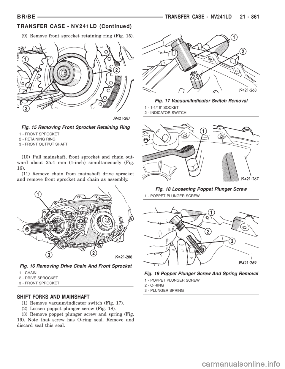
(9) Remove front sprocket retaining ring (Fig. 15).
(10) Pull mainshaft, front sprocket and chain out-
ward about 25.4 mm (1-inch) simultaneously (Fig.
16).
(11) Remove chain from mainshaft drive sprocket
and remove front sprocket and chain as assembly.
SHIFT FORKS AND MAINSHAFT
(1) Remove vacuum/indicator switch (Fig. 17).
(2) Loosen poppet plunger screw (Fig. 18).
(3) Remove poppet plunger screw and spring (Fig.
19). Note that screw has O-ring seal. Remove and
discard seal this seal.
Fig. 15 Removing Front Sprocket Retaining Ring
1 - FRONT SPROCKET
2 - RETAINING RING
3 - FRONT OUTPUT SHAFT
Fig. 16 Removing Drive Chain And Front Sprocket
1 - CHAIN
2 - DRIVE SPROCKET
3 - FRONT SPROCKET
Fig. 17 Vacuum/Indicator Switch Removal
1 - 1-1/16º SOCKET
2 - INDICATOR SWITCH
Fig. 18 Loosening Poppet Plunger Screw
1 - POPPET PLUNGER SCREW
Fig. 19 Poppet Plunger Screw And Spring Removal
1 - POPPET PLUNGER SCREW
2 - O-RING
3 - PLUNGER SPRING
BR/BETRANSFER CASE - NV241LD 21 - 861
TRANSFER CASE - NV241LD (Continued)
Page 2497 of 2889
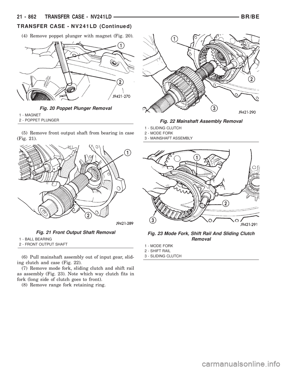
(4) Remove poppet plunger with magnet (Fig. 20).
(5) Remove front output shaft from bearing in case
(Fig. 21).
(6) Pull mainshaft assembly out of input gear, slid-
ing clutch and case (Fig. 22).
(7) Remove mode fork, sliding clutch and shift rail
as assembly (Fig. 23). Note which way clutch fits in
fork (long side of clutch goes to front).
(8) Remove range fork retaining ring.
Fig. 20 Poppet Plunger Removal
1 - MAGNET
2 - POPPET PLUNGER
Fig. 21 Front Output Shaft Removal
1 - BALL BEARING
2 - FRONT OUTPUT SHAFT
Fig. 22 Mainshaft Assembly Removal
1 - SLIDING CLUTCH
2 - MODE FORK
3 - MAINSHAFT ASSEMBLY
Fig. 23 Mode Fork, Shift Rail And Sliding Clutch
Removal
1 - MODE FORK
2 - SHIFT RAIL
3 - SLIDING CLUTCH
21 - 862 TRANSFER CASE - NV241LDBR/BE
TRANSFER CASE - NV241LD (Continued)
Page 2498 of 2889
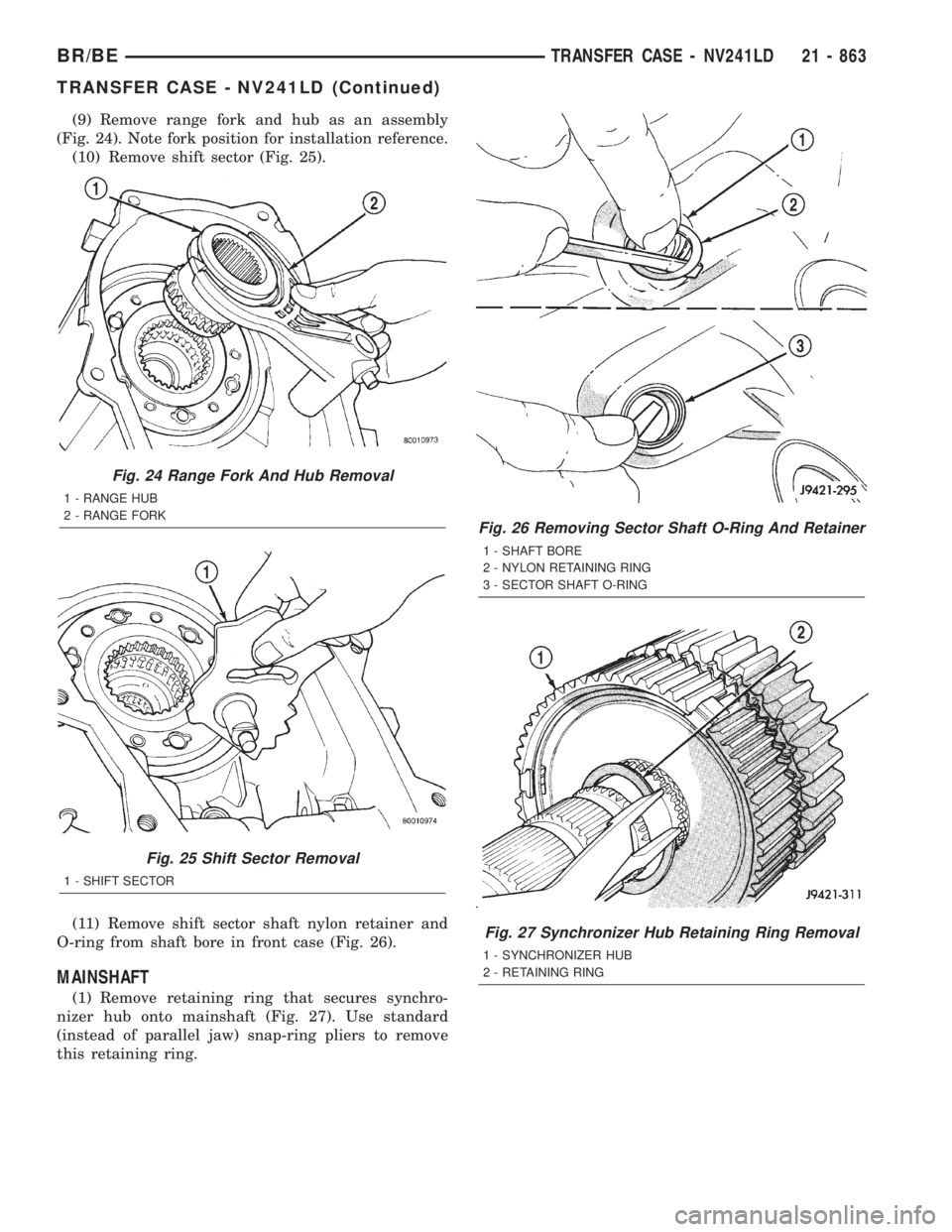
(9) Remove range fork and hub as an assembly
(Fig. 24). Note fork position for installation reference.
(10) Remove shift sector (Fig. 25).
(11) Remove shift sector shaft nylon retainer and
O-ring from shaft bore in front case (Fig. 26).
MAINSHAFT
(1) Remove retaining ring that secures synchro-
nizer hub onto mainshaft (Fig. 27). Use standard
(instead of parallel jaw) snap-ring pliers to remove
this retaining ring.
Fig. 24 Range Fork And Hub Removal
1 - RANGE HUB
2 - RANGE FORK
Fig. 25 Shift Sector Removal
1 - SHIFT SECTOR
Fig. 26 Removing Sector Shaft O-Ring And Retainer
1 - SHAFT BORE
2 - NYLON RETAINING RING
3 - SECTOR SHAFT O-RING
Fig. 27 Synchronizer Hub Retaining Ring Removal
1 - SYNCHRONIZER HUB
2 - RETAINING RING
BR/BETRANSFER CASE - NV241LD 21 - 863
TRANSFER CASE - NV241LD (Continued)
Page 2499 of 2889
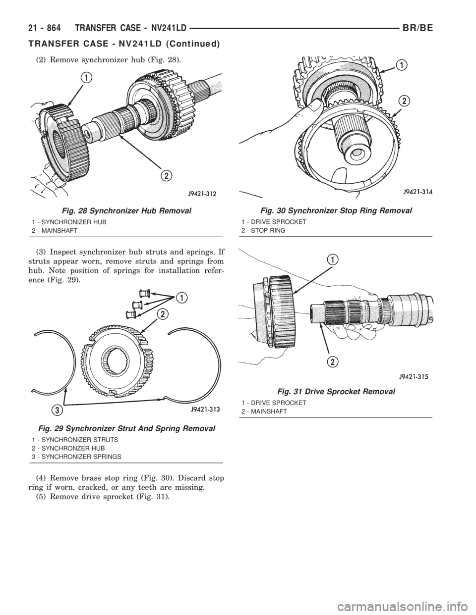
(2) Remove synchronizer hub (Fig. 28).
(3) Inspect synchronizer hub struts and springs. If
struts appear worn, remove struts and springs from
hub. Note position of springs for installation refer-
ence (Fig. 29).
(4) Remove brass stop ring (Fig. 30). Discard stop
ring if worn, cracked, or any teeth are missing.
(5) Remove drive sprocket (Fig. 31).
Fig. 28 Synchronizer Hub Removal
1 - SYNCHRONIZER HUB
2 - MAINSHAFT
Fig. 29 Synchronizer Strut And Spring Removal
1 - SYNCHRONIZER STRUTS
2 - SYNCHRONZER HUB
3 - SYNCHRONIZER SPRINGS
Fig. 30 Synchronizer Stop Ring Removal
1 - DRIVE SPROCKET
2 - STOP RING
Fig. 31 Drive Sprocket Removal
1 - DRIVE SPROCKET
2 - MAINSHAFT
21 - 864 TRANSFER CASE - NV241LDBR/BE
TRANSFER CASE - NV241LD (Continued)
Page 2500 of 2889
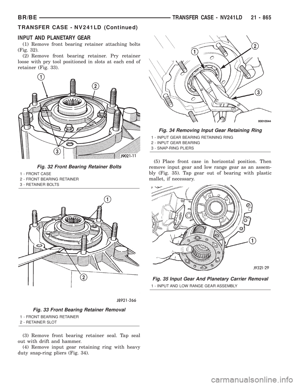
INPUT AND PLANETARY GEAR
(1) Remove front bearing retainer attaching bolts
(Fig. 32).
(2) Remove front bearing retainer. Pry retainer
loose with pry tool positioned in slots at each end of
retainer (Fig. 33).
(3) Remove front bearing retainer seal. Tap seal
out with drift and hammer.
(4) Remove input gear retaining ring with heavy
duty snap-ring pliers (Fig. 34).(5) Place front case in horizontal position. Then
remove input gear and low range gear as an assem-
bly (Fig. 35). Tap gear out of bearing with plastic
mallet, if necessary.
Fig. 32 Front Bearing Retainer Bolts
1 - FRONT CASE
2 - FRONT BEARING RETAINER
3 - RETAINER BOLTS
Fig. 33 Front Bearing Retainer Removal
1 - FRONT BEARING RETAINER
2 - RETAINER SLOT
Fig. 34 Removing Input Gear Retaining Ring
1 - INPUT GEAR BEARING RETAINING RING
2 - INPUT GEAR BEARING
3 - SNAP-RING PLIERS
Fig. 35 Input Gear And Planetary Carrier Removal
1 - INPUT AND LOW RANGE GEAR ASSEMBLY
BR/BETRANSFER CASE - NV241LD 21 - 865
TRANSFER CASE - NV241LD (Continued)