DODGE RAM 2001 Service Repair Manual
Manufacturer: DODGE, Model Year: 2001, Model line: RAM, Model: DODGE RAM 2001Pages: 2889, PDF Size: 68.07 MB
Page 351 of 2889
(3) Fill coolant reserve/overflow tank to the FULL
mark.
(4) Start and operate engine until thermostat
opens. Upper radiator hose should be warm to touch.
(5) If necessary, add 50/50 water and antifreeze
mixture to the coolant reserve/overflow tank to main-
tain coolant level. This level should be between the
ADD and FULL marks. The level in the reserve/over-
flow tank may drop below the ADD mark after three
or four warm-up and cool-down cycles.
STANDARD PROCEDUREÐADDING
ADDITIONAL COOLANT
Do not remove radiator cap to add coolant to
system.When adding coolant to maintain correct
level, do so at coolant reserve/overflow tank. Use a
50/50 mixture of ethylene glycol antifreeze containing
Alugard 340-2yand low mineral content water.
Remove radiator cap only for testing or when refill-
ing system after service. Removing cap unnecessarily
can cause loss of coolant and allow air to enter sys-
tem, which produces corrosion.
STANDARD PROCEDUREÐCOOLANT LEVEL
CHECK
NOTE: Do not remove radiator cap for routine cool-
ant level inspections. The coolant level can be
checked at coolant recovery bottle .
The coolant reserve/overflow system provides a
quick method for determining coolant level without
removing radiator pressure cap. With engine not run-
ning, open the coolant recovery bottle cap and
remove coolant level indicator dipstick to observe
coolant level in coolant recovery bottle. The coolant
level should be between ADD and FULL marks. If
the coolant level is at or below the ADD mark, fill
the recovery bottle with a 50/50 mixture of antifreeze
and water ONE QUART AT A TIME. Repeat this pro-
cedure until the coolant level is at the FULL mark
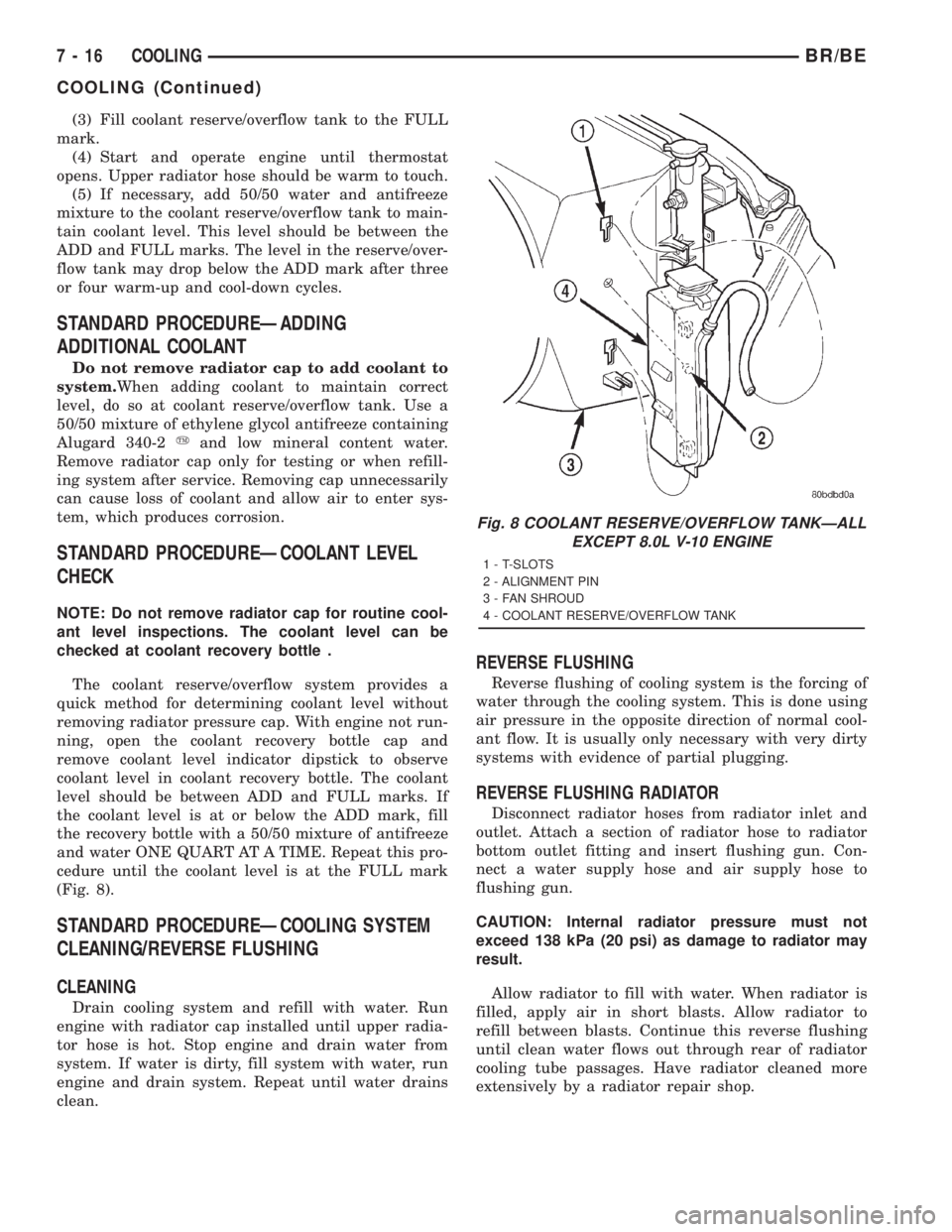
(Fig. 8).
STANDARD PROCEDUREÐCOOLING SYSTEM
CLEANING/REVERSE FLUSHING
CLEANING
Drain cooling system and refill with water. Run
engine with radiator cap installed until upper radia-
tor hose is hot. Stop engine and drain water from
system. If water is dirty, fill system with water, run
engine and drain system. Repeat until water drains
clean.
REVERSE FLUSHING
Reverse flushing of cooling system is the forcing of
water through the cooling system. This is done using
air pressure in the opposite direction of normal cool-
ant flow. It is usually only necessary with very dirty
systems with evidence of partial plugging.
REVERSE FLUSHING RADIATOR
Disconnect radiator hoses from radiator inlet and
outlet. Attach a section of radiator hose to radiator
bottom outlet fitting and insert flushing gun. Con-
nect a water supply hose and air supply hose to
flushing gun.
CAUTION: Internal radiator pressure must not
exceed 138 kPa (20 psi) as damage to radiator may
result.
Allow radiator to fill with water. When radiator is
filled, apply air in short blasts. Allow radiator to
refill between blasts. Continue this reverse flushing
until clean water flows out through rear of radiator
cooling tube passages. Have radiator cleaned more
extensively by a radiator repair shop.
Fig. 8 COOLANT RESERVE/OVERFLOW TANKÐALL
EXCEPT 8.0L V-10 ENGINE
1 - T-SLOTS
2 - ALIGNMENT PIN
3 - FAN SHROUD
4 - COOLANT RESERVE/OVERFLOW TANK
7 - 16 COOLINGBR/BE
COOLING (Continued)
Page 352 of 2889
REVERSE FLUSHING ENGINE
Drain cooling system. Remove thermostat housing
and thermostat. Install thermostat housing. Discon-
nect radiator upper hose from radiator and attach
flushing gun to hose. Disconnect radiator lower hose
from water pump and attach a lead-away hose to
water pump inlet fitting.
CAUTION: On vehicles equipped with a heater water
control valve, be sure heater control valve is closed
(heat off). This will prevent coolant flow with scale
and other deposits from entering heater core.
Connect water supply hose and air supply hose to
flushing gun. Allow engine to fill with water. When
engine is filled, apply air in short blasts, allowing
system to fill between air blasts. Continue until clean
water flows through the lead away hose.
Remove lead away hose, flushing gun, water sup-
ply hose and air supply hose. Remove thermostat
housing and install thermostat. Install thermostat
housing with a replacement gasket. Refer to Thermo-
stat Replacement. Connect radiator hoses. Refill cool-
ing system with correct antifreeze/water mixture.
Refer to Refilling the Cooling System.
CHEMICAL CLEANING
In some instances, use a radiator cleaner (Mopar
Radiator Kleen or equivalent) before flushing. This
will soften scale and other deposits and aid flushing
operation.
CAUTION: Follow manufacturers instructions when
using these products.
STANDARD PROCEDUREÐCOOLANT
SELECTION-ADDITIVES
The presence of aluminum components in the cool-
ing system requires strict corrosion protection. Main-
tain coolant at specified level with a mixture of
ethylene glycol based antifreeze and water. If coolant
becomes contaminated or looses color, drain and flush
cooling system and fill with correctly mixed solution.
CAUTION: Do not use coolant additives that are
claimed to improve engine cooling.
SPECIFICATIONS
TORQUE
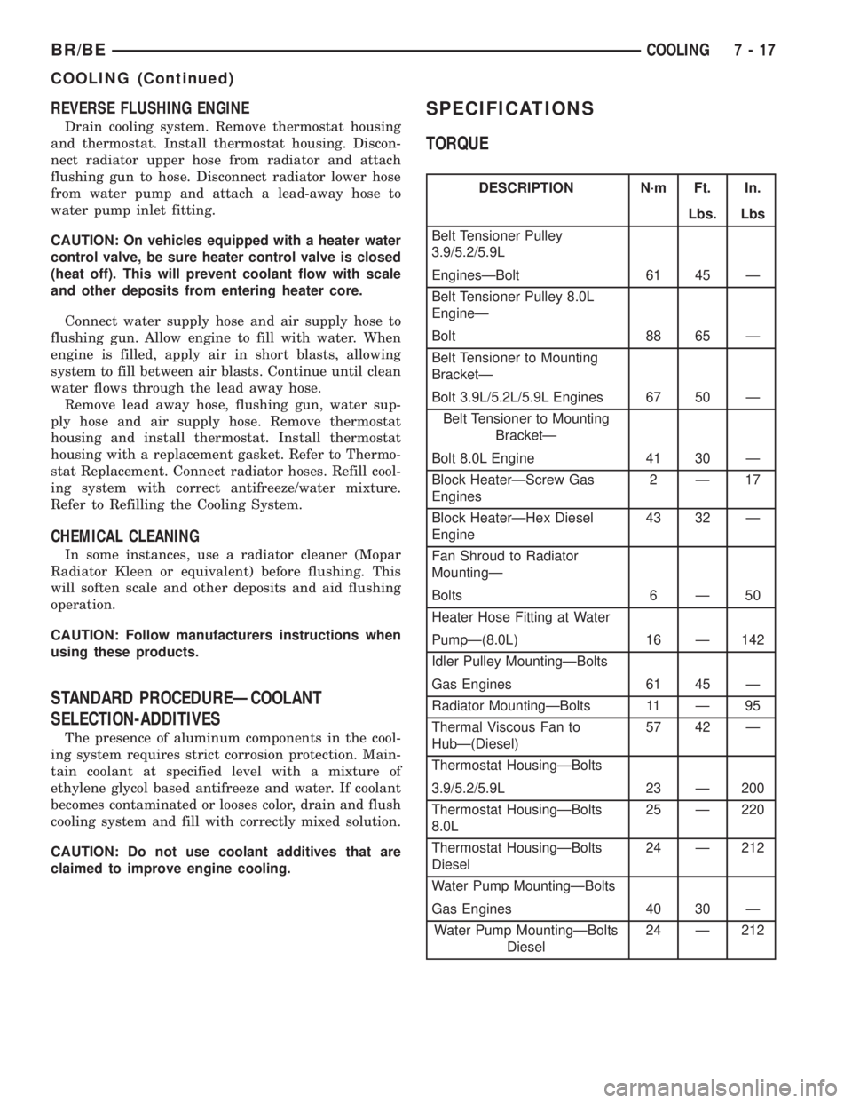
DESCRIPTION N´m Ft. In.
Lbs. Lbs
Belt Tensioner Pulley
3.9/5.2/5.9L
EnginesÐBolt 61 45 Ð
Belt Tensioner Pulley 8.0L
EngineÐ
Bolt 88 65 Ð
Belt Tensioner to Mounting
BracketÐ
Bolt 3.9L/5.2L/5.9L Engines 67 50 Ð
Belt Tensioner to Mounting
BracketÐ
Bolt 8.0L Engine 41 30 Ð
Block HeaterÐScrew Gas
Engines2Ð17
Block HeaterÐHex Diesel
Engine43 32 Ð
Fan Shroud to Radiator
MountingÐ
Bolts 6 Ð 50
Heater Hose Fitting at Water
PumpÐ(8.0L) 16 Ð 142
Idler Pulley MountingÐBolts
Gas Engines 61 45 Ð
Radiator MountingÐBolts 11 Ð 95
Thermal Viscous Fan to
HubÐ(Diesel)57 42 Ð
Thermostat HousingÐBolts
3.9/5.2/5.9L 23 Ð 200
Thermostat HousingÐBolts
8.0L25 Ð 220
Thermostat HousingÐBolts
Diesel24 Ð 212
Water Pump MountingÐBolts
Gas Engines 40 30 Ð
Water Pump MountingÐBolts
Diesel24 Ð 212
BR/BECOOLING 7 - 17
COOLING (Continued)
Page 353 of 2889
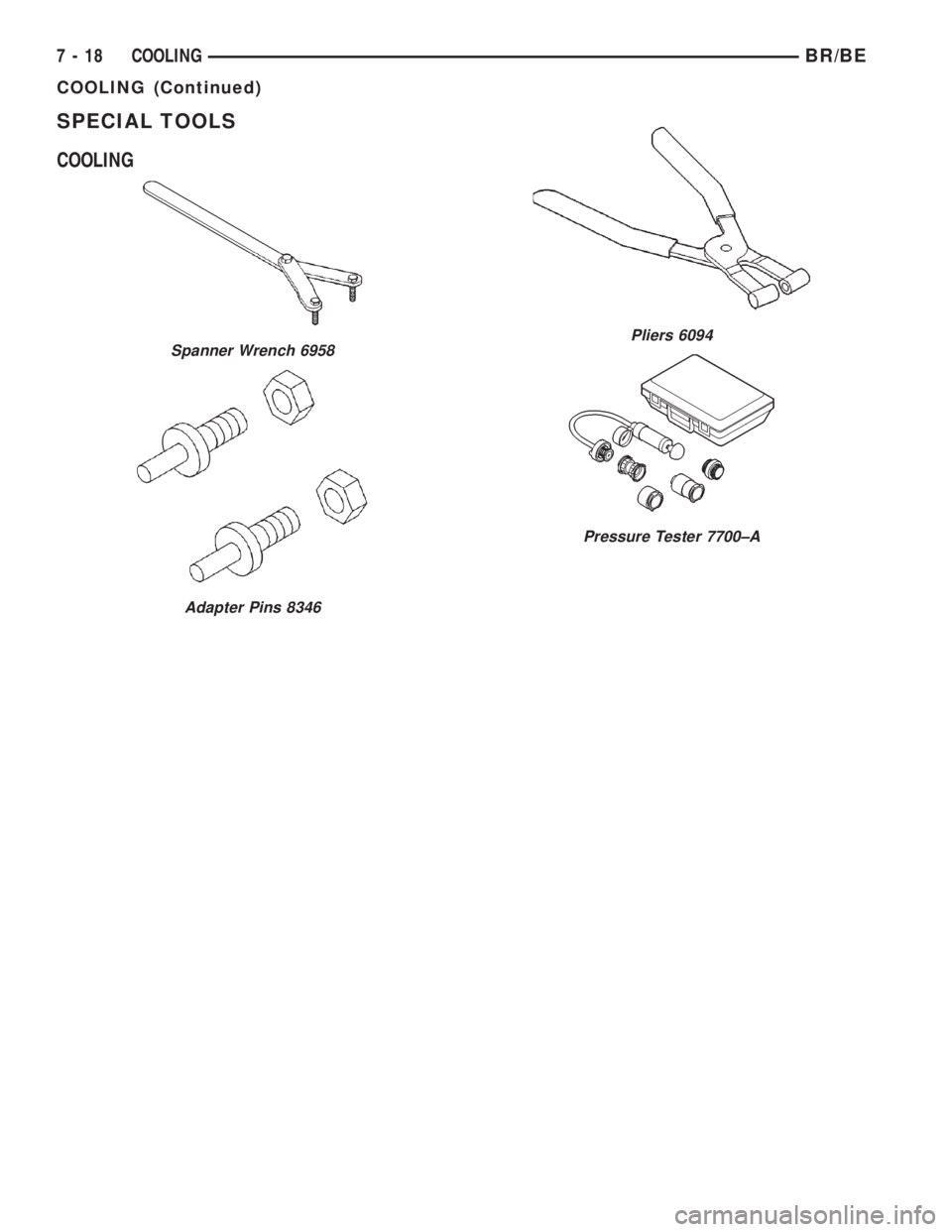
SPECIAL TOOLS
COOLING
Spanner Wrench 6958
Adapter Pins 8346
Pliers 6094
Pressure Tester 7700±A
7 - 18 COOLINGBR/BE
COOLING (Continued)
Page 354 of 2889
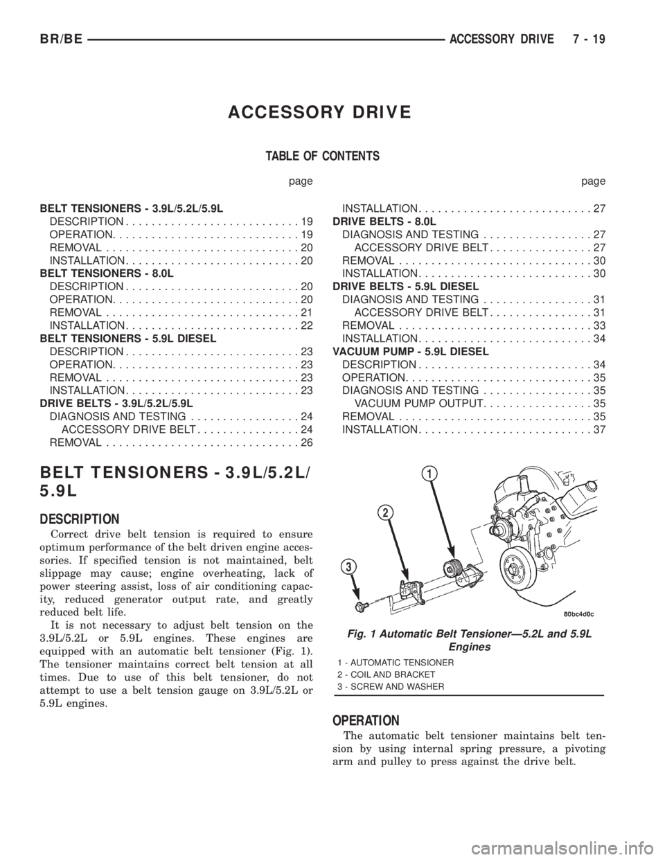
ACCESSORY DRIVE
TABLE OF CONTENTS
page page
BELT TENSIONERS - 3.9L/5.2L/5.9L
DESCRIPTION...........................19
OPERATION.............................19
REMOVAL..............................20
INSTALLATION...........................20
BELT TENSIONERS - 8.0L
DESCRIPTION...........................20
OPERATION.............................20
REMOVAL..............................21
INSTALLATION...........................22
BELT TENSIONERS - 5.9L DIESEL
DESCRIPTION...........................23
OPERATION.............................23
REMOVAL..............................23
INSTALLATION...........................23
DRIVE BELTS - 3.9L/5.2L/5.9L
DIAGNOSIS AND TESTING.................24
ACCESSORY DRIVE BELT................24
REMOVAL..............................26INSTALLATION...........................27
DRIVE BELTS - 8.0L
DIAGNOSIS AND TESTING.................27
ACCESSORY DRIVE BELT................27
REMOVAL..............................30
INSTALLATION...........................30
DRIVE BELTS - 5.9L DIESEL
DIAGNOSIS AND TESTING.................31
ACCESSORY DRIVE BELT................31
REMOVAL..............................33
INSTALLATION...........................34
VACUUM PUMP - 5.9L DIESEL
DESCRIPTION...........................34
OPERATION.............................35
DIAGNOSIS AND TESTING.................35
VACUUM PUMP OUTPUT.................35
REMOVAL..............................35
INSTALLATION...........................37
BELT TENSIONERS - 3.9L/5.2L/
5.9L
DESCRIPTION
Correct drive belt tension is required to ensure
optimum performance of the belt driven engine acces-
sories. If specified tension is not maintained, belt
slippage may cause; engine overheating, lack of
power steering assist, loss of air conditioning capac-
ity, reduced generator output rate, and greatly
reduced belt life.
It is not necessary to adjust belt tension on the
3.9L/5.2L or 5.9L engines. These engines are
equipped with an automatic belt tensioner (Fig. 1).
The tensioner maintains correct belt tension at all
times. Due to use of this belt tensioner, do not
attempt to use a belt tension gauge on 3.9L/5.2L or
5.9L engines.
OPERATION
The automatic belt tensioner maintains belt ten-
sion by using internal spring pressure, a pivoting
arm and pulley to press against the drive belt.
Fig. 1 Automatic Belt TensionerÐ5.2L and 5.9L
Engines
1 - AUTOMATIC TENSIONER
2 - COIL AND BRACKET
3 - SCREW AND WASHER
BR/BEACCESSORY DRIVE 7 - 19
Page 355 of 2889
REMOVAL
WARNING: BECAUSE OF HIGH SPRING PRES-
SURE, DO NOT ATTEMPT TO DISASSEMBLE AUTO-
MATIC TENSIONER. UNIT IS SERVICED AS AN
ASSEMBLY (EXCEPT FOR PULLEY).
(1) Remove accessory drive belt. (Refer to 7 -
COOLING/ACCESSORY DRIVE/DRIVE BELTS -
REMOVAL).
(2) Disconnect wiring and secondary cable from
ignition coil.
(3) Remove ignition coil from coil mounting
bracket (two bolts). Do not remove coil mounting
bracket from cylinder head.
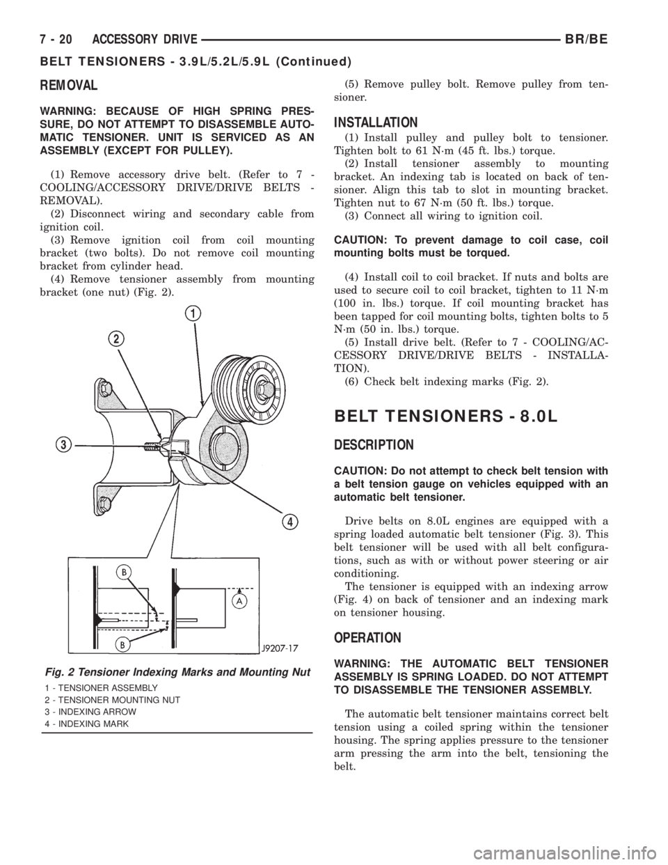
(4) Remove tensioner assembly from mounting
bracket (one nut) (Fig. 2).(5) Remove pulley bolt. Remove pulley from ten-
sioner.
INSTALLATION
(1) Install pulley and pulley bolt to tensioner.
Tighten bolt to 61 N´m (45 ft. lbs.) torque.
(2) Install tensioner assembly to mounting
bracket. An indexing tab is located on back of ten-
sioner. Align this tab to slot in mounting bracket.
Tighten nut to 67 N´m (50 ft. lbs.) torque.
(3) Connect all wiring to ignition coil.
CAUTION: To prevent damage to coil case, coil
mounting bolts must be torqued.
(4) Install coil to coil bracket. If nuts and bolts are
used to secure coil to coil bracket, tighten to 11 N´m
(100 in. lbs.) torque. If coil mounting bracket has
been tapped for coil mounting bolts, tighten bolts to 5
N´m (50 in. lbs.) torque.
(5) Install drive belt. (Refer to 7 - COOLING/AC-
CESSORY DRIVE/DRIVE BELTS - INSTALLA-
TION).
(6) Check belt indexing marks (Fig. 2).
BELT TENSIONERS - 8.0L
DESCRIPTION
CAUTION: Do not attempt to check belt tension with
a belt tension gauge on vehicles equipped with an
automatic belt tensioner.
Drive belts on 8.0L engines are equipped with a
spring loaded automatic belt tensioner (Fig. 3). This
belt tensioner will be used with all belt configura-
tions, such as with or without power steering or air
conditioning.
The tensioner is equipped with an indexing arrow
(Fig. 4) on back of tensioner and an indexing mark
on tensioner housing.
OPERATION
WARNING: THE AUTOMATIC BELT TENSIONER
ASSEMBLY IS SPRING LOADED. DO NOT ATTEMPT
TO DISASSEMBLE THE TENSIONER ASSEMBLY.
The automatic belt tensioner maintains correct belt
tension using a coiled spring within the tensioner
housing. The spring applies pressure to the tensioner
arm pressing the arm into the belt, tensioning the
belt.Fig. 2 Tensioner Indexing Marks and Mounting Nut
1 - TENSIONER ASSEMBLY
2 - TENSIONER MOUNTING NUT
3 - INDEXING ARROW
4 - INDEXING MARK
7 - 20 ACCESSORY DRIVEBR/BE
BELT TENSIONERS - 3.9L/5.2L/5.9L (Continued)
Page 356 of 2889
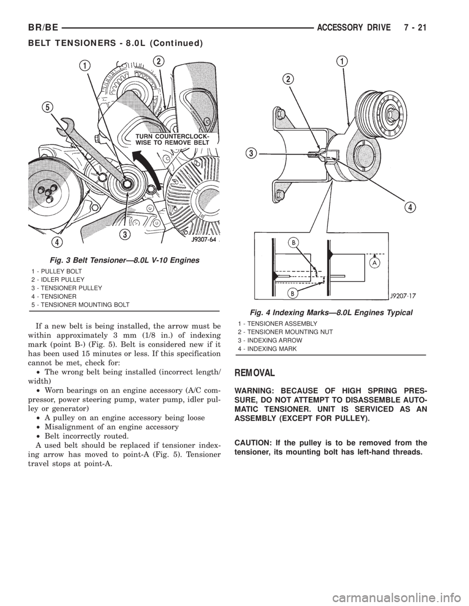
If a new belt is being installed, the arrow must be
within approximately 3 mm (1/8 in.) of indexing
mark (point B-) (Fig. 5). Belt is considered new if it
has been used 15 minutes or less. If this specification
cannot be met, check for:
²The wrong belt being installed (incorrect length/
width)
²Worn bearings on an engine accessory (A/C com-
pressor, power steering pump, water pump, idler pul-
ley or generator)
²A pulley on an engine accessory being loose
²Misalignment of an engine accessory
²Belt incorrectly routed.
A used belt should be replaced if tensioner index-
ing arrow has moved to point-A (Fig. 5). Tensioner
travel stops at point-A.
REMOVAL
WARNING: BECAUSE OF HIGH SPRING PRES-
SURE, DO NOT ATTEMPT TO DISASSEMBLE AUTO-
MATIC TENSIONER. UNIT IS SERVICED AS AN
ASSEMBLY (EXCEPT FOR PULLEY).
CAUTION: If the pulley is to be removed from the
tensioner, its mounting bolt has left-hand threads.
Fig. 3 Belt TensionerÐ8.0L V-10 Engines
1 - PULLEY BOLT
2 - IDLER PULLEY
3 - TENSIONER PULLEY
4 - TENSIONER
5 - TENSIONER MOUNTING BOLT
Fig. 4 Indexing MarksÐ8.0L Engines Typical
1 - TENSIONER ASSEMBLY
2 - TENSIONER MOUNTING NUT
3 - INDEXING ARROW
4 - INDEXING MARK
BR/BEACCESSORY DRIVE 7 - 21
BELT TENSIONERS - 8.0L (Continued)
Page 357 of 2889
(1) Remove accessory drive belt (Refer to 7 -
COOLING/ACCESSORY DRIVE/DRIVE BELTS -
REMOVAL).
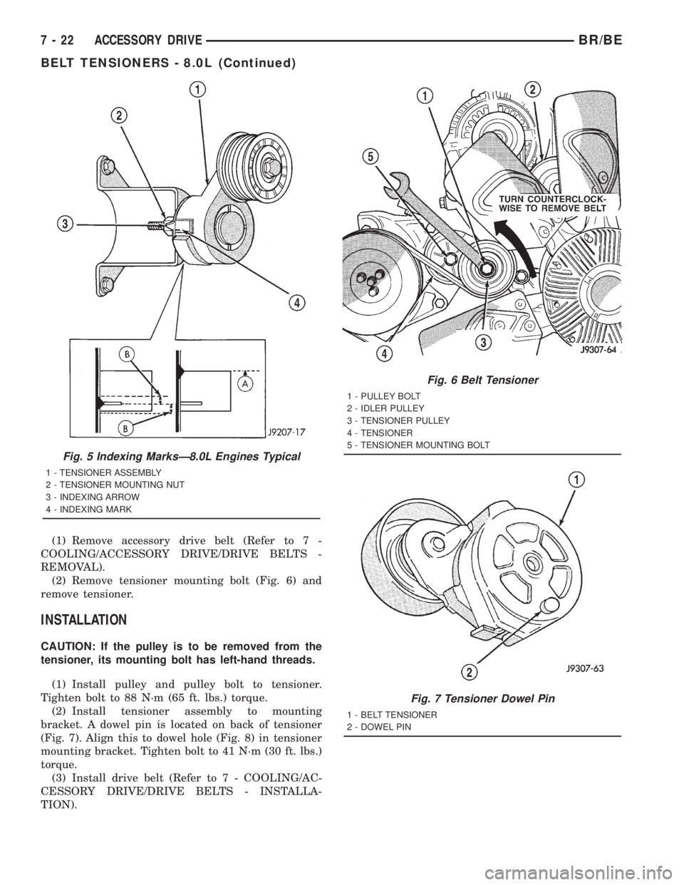
(2) Remove tensioner mounting bolt (Fig. 6) and
remove tensioner.
INSTALLATION
CAUTION: If the pulley is to be removed from the
tensioner, its mounting bolt has left-hand threads.
(1) Install pulley and pulley bolt to tensioner.
Tighten bolt to 88 N´m (65 ft. lbs.) torque.
(2) Install tensioner assembly to mounting
bracket. A dowel pin is located on back of tensioner
(Fig. 7). Align this to dowel hole (Fig. 8) in tensioner
mounting bracket. Tighten bolt to 41 N´m (30 ft. lbs.)
torque.
(3) Install drive belt (Refer to 7 - COOLING/AC-
CESSORY DRIVE/DRIVE BELTS - INSTALLA-
TION).
Fig. 5 Indexing MarksÐ8.0L Engines Typical
1 - TENSIONER ASSEMBLY
2 - TENSIONER MOUNTING NUT
3 - INDEXING ARROW
4 - INDEXING MARK
Fig. 6 Belt Tensioner
1 - PULLEY BOLT
2 - IDLER PULLEY
3 - TENSIONER PULLEY
4 - TENSIONER
5 - TENSIONER MOUNTING BOLT
Fig. 7 Tensioner Dowel Pin
1 - BELT TENSIONER
2 - DOWEL PIN
7 - 22 ACCESSORY DRIVEBR/BE
BELT TENSIONERS - 8.0L (Continued)
Page 358 of 2889
BELT TENSIONERS - 5.9L
DIESEL
DESCRIPTION
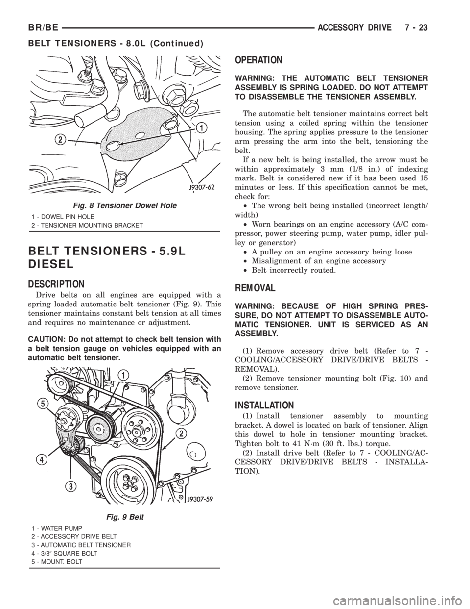
Drive belts on all engines are equipped with a
spring loaded automatic belt tensioner (Fig. 9). This
tensioner maintains constant belt tension at all times
and requires no maintenance or adjustment.
CAUTION: Do not attempt to check belt tension with
a belt tension gauge on vehicles equipped with an
automatic belt tensioner.
OPERATION
WARNING: THE AUTOMATIC BELT TENSIONER
ASSEMBLY IS SPRING LOADED. DO NOT ATTEMPT
TO DISASSEMBLE THE TENSIONER ASSEMBLY.
The automatic belt tensioner maintains correct belt
tension using a coiled spring within the tensioner
housing. The spring applies pressure to the tensioner
arm pressing the arm into the belt, tensioning the
belt.
If a new belt is being installed, the arrow must be
within approximately 3 mm (1/8 in.) of indexing
mark. Belt is considered new if it has been used 15
minutes or less. If this specification cannot be met,
check for:
²The wrong belt being installed (incorrect length/
width)
²Worn bearings on an engine accessory (A/C com-
pressor, power steering pump, water pump, idler pul-
ley or generator)
²A pulley on an engine accessory being loose
²Misalignment of an engine accessory
²Belt incorrectly routed.
REMOVAL
WARNING: BECAUSE OF HIGH SPRING PRES-
SURE, DO NOT ATTEMPT TO DISASSEMBLE AUTO-
MATIC TENSIONER. UNIT IS SERVICED AS AN
ASSEMBLY.
(1) Remove accessory drive belt (Refer to 7 -
COOLING/ACCESSORY DRIVE/DRIVE BELTS -
REMOVAL).
(2) Remove tensioner mounting bolt (Fig. 10) and
remove tensioner.
INSTALLATION
(1) Install tensioner assembly to mounting
bracket. A dowel is located on back of tensioner. Align
this dowel to hole in tensioner mounting bracket.
Tighten bolt to 41 N´m (30 ft. lbs.) torque.
(2) Install drive belt (Refer to 7 - COOLING/AC-
CESSORY DRIVE/DRIVE BELTS - INSTALLA-
TION).
Fig. 8 Tensioner Dowel Hole
1 - DOWEL PIN HOLE
2 - TENSIONER MOUNTING BRACKET
Fig. 9 Belt
1 - WATER PUMP
2 - ACCESSORY DRIVE BELT
3 - AUTOMATIC BELT TENSIONER
4 - 3/89SQUARE BOLT
5 - MOUNT. BOLT
BR/BEACCESSORY DRIVE 7 - 23
BELT TENSIONERS - 8.0L (Continued)
Page 359 of 2889
DRIVE BELTS - 3.9L/5.2L/5.9L
DIAGNOSIS AND TESTINGÐACCESSORY
DRIVE BELT
VISUAL DIAGNOSIS
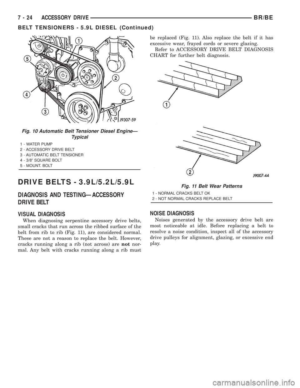
When diagnosing serpentine accessory drive belts,
small cracks that run across the ribbed surface of the
belt from rib to rib (Fig. 11), are considered normal.
These are not a reason to replace the belt. However,
cracks running along a rib (not across) arenotnor-
mal. Any belt with cracks running along a rib mustbe replaced (Fig. 11). Also replace the belt if it has
excessive wear, frayed cords or severe glazing.
Refer to ACCESSORY DRIVE BELT DIAGNOSIS
CHART for further belt diagnosis.
NOISE DIAGNOSIS
Noises generated by the accessory drive belt are
most noticeable at idle. Before replacing a belt to
resolve a noise condition, inspect all of the accessory
drive pulleys for alignment, glazing, or excessive end
play.
Fig. 10 Automatic Belt Tensioner Diesel EngineÐ
Typical
1 - WATER PUMP
2 - ACCESSORY DRIVE BELT
3 - AUTOMATIC BELT TENSIONER
4 - 3/89SQUARE BOLT
5 - MOUNT. BOLT
Fig. 11 Belt Wear Patterns
1 - NORMAL CRACKS BELT OK
2 - NOT NORMAL CRACKS REPLACE BELT
7 - 24 ACCESSORY DRIVEBR/BE
BELT TENSIONERS - 5.9L DIESEL (Continued)
Page 360 of 2889
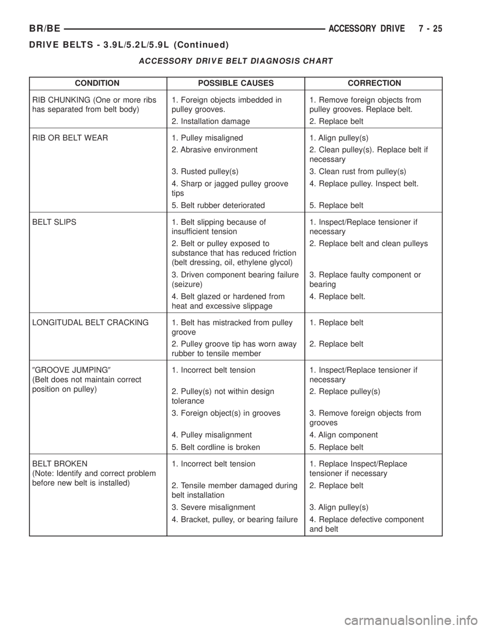
ACCESSORY DRIVE BELT DIAGNOSIS CHART
CONDITION POSSIBLE CAUSES CORRECTION
RIB CHUNKING (One or more ribs
has separated from belt body)1. Foreign objects imbedded in
pulley grooves.1. Remove foreign objects from
pulley grooves. Replace belt.
2. Installation damage 2. Replace belt
RIB OR BELT WEAR 1. Pulley misaligned 1. Align pulley(s)
2. Abrasive environment 2. Clean pulley(s). Replace belt if
necessary
3. Rusted pulley(s) 3. Clean rust from pulley(s)
4. Sharp or jagged pulley groove
tips4. Replace pulley. Inspect belt.
5. Belt rubber deteriorated 5. Replace belt
BELT SLIPS 1. Belt slipping because of
insufficient tension1. Inspect/Replace tensioner if
necessary
2. Belt or pulley exposed to
substance that has reduced friction
(belt dressing, oil, ethylene glycol)2. Replace belt and clean pulleys
3. Driven component bearing failure
(seizure)3. Replace faulty component or
bearing
4. Belt glazed or hardened from
heat and excessive slippage4. Replace belt.
LONGITUDAL BELT CRACKING 1. Belt has mistracked from pulley
groove1. Replace belt
2. Pulley groove tip has worn away
rubber to tensile member2. Replace belt
9GROOVE JUMPING9
(Belt does not maintain correct
position on pulley)1. Incorrect belt tension 1. Inspect/Replace tensioner if
necessary
2. Pulley(s) not within design
tolerance2. Replace pulley(s)
3. Foreign object(s) in grooves 3. Remove foreign objects from
grooves
4. Pulley misalignment 4. Align component
5. Belt cordline is broken 5. Replace belt
BELT BROKEN
(Note: Identify and correct problem
before new belt is installed)1. Incorrect belt tension 1. Replace Inspect/Replace
tensioner if necessary
2. Tensile member damaged during
belt installation2. Replace belt
3. Severe misalignment 3. Align pulley(s)
4. Bracket, pulley, or bearing failure 4. Replace defective component
and belt
BR/BEACCESSORY DRIVE 7 - 25
DRIVE BELTS - 3.9L/5.2L/5.9L (Continued)