DODGE RAM 2002 Service Repair Manual
Manufacturer: DODGE, Model Year: 2002, Model line: RAM, Model: DODGE RAM 2002Pages: 2255, PDF Size: 62.07 MB
Page 1071 of 2255
(4) Press firmly on the cigar lighter or power out-
let receptacle base until the retaining bosses of the
mount are fully engaged in their receptacles.
(5) Install the cigar lighter knob and element into
the cigar lighter receptacle base, or the protective cap
into the power outlet receptacle base.
(6) Reconnect the battery negative cable.
HORN RELAY
DESCRIPTION
The horn relay is a International Standards Orga-
nization (ISO) micro-relay. The terminal designations
and functions are the same as a conventional ISO
relay. However, the micro-relay terminal orientation
(or footprint) is different, current capacity is lower,
and the relay case dimensions are smaller than those
of the conventional ISO relay.
The horn relay is a electromechanical device that
switches battery current to the horn when the horn
switch or when the high-line or premium Central
Timer Module (CTM) grounds the relay coil. See
Horn Relay in the Diagnosis and Testing section of
this group for more information.
The horn relay is located in the Power Distribution
Center (PDC), in the engine compartment. Refer to
the PDC label for relay identification and location.
If a problem is encountered with a continuously
sounding horn, it can usually be quickly resolved by
removing the horn relay from the PDC until further
diagnosis is completed.
The horn relay cannot be repaired and, if faulty or
damaged, it must be replaced.
DIAGNOSIS AND TESTING - HORN RELAY
The headlamp (or security) relay and the horn
relay are located in the Power Distribution Center
(PDC) in the engine compartment. Each of these
relays can be tested as described in the following pro-
cedure, however the circuits they are used in do vary.
To test the relay circuits, refer to the circuit descrip-
tions and diagrams in Wiring Diagrams.
WARNING: ON VEHICLES EQUIPPED WITH AIR-
BAGS, REFER TO THE RESTRAINTS SECTION OF
THE SERVICE MANUAL BEFORE ATTEMPTING ANY
STEERING WHEEL, STEERING COLUMN, OR
INSTRUMENT PANEL COMPONENT DIAGNOSIS OR
SERVICE. FAILURE TO TAKE THE PROPER PRE-
CAUTIONS COULD RESULT IN ACCIDENTAL AIR-
BAG DEPLOYMENT AND POSSIBLE PERSONAL
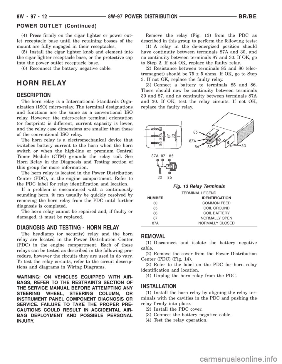
INJURY.Remove the relay (Fig. 13) from the PDC as
described in this group to perform the following tests:
(1) A relay in the de-energized position should
have continuity between terminals 87A and 30, and
no continuity between terminals 87 and 30. If OK, go
to Step 2. If not OK, replace the faulty relay.
(2) Resistance between terminals 85 and 86 (elec-
tromagnet) should be 75 5 ohms. If OK, go to Step
3. If not OK, replace the faulty relay.
(3) Connect a battery to terminals 85 and 86.
There should now be continuity between terminals
30 and 87, and no continuity between terminals 87A
and 30. If OK, test the relay circuits. If not OK,
replace the faulty relay.REMOVAL
(1) Disconnect and isolate the battery negative
cable.
(2) Remove the cover from the Power Distribution
Center (PDC) (Fig. 14).
(3) Refer to the label on the PDC for horn relay
identification and location.
(4) Unplug the horn relay from the PDC.
INSTALLATION
(1) Install the horn relay by aligning the relay ter-
minals with the cavities in the PDC and pushing the
relay firmly into place.
(2) Install the PDC cover.
(3) Connect the battery negative cable.
(4) Test the relay operation.
Fig. 13 Relay Terminals
TERMINAL LEGEND
NUMBER IDENTIFICATION
30 COMMON FEED
85 COIL GROUND
86 COIL BATTERY
87 NORMALLY OPEN
87A NORMALLY CLOSED
8W - 97 - 12 8W-97 POWER DISTRIBUTIONBR/BE
POWER OUTLET (Continued)
Page 1072 of 2255
HEADLAMP RELAY
DESCRIPTION
The headlamp (or security) relay is a International
Standards Organization (ISO) micro-relay. The termi-
nal designations and functions are the same as a con-
ventional ISO relay. However, the micro-relay
terminal orientation (or footprint) is different, cur-
rent capacity is lower, and the relay case dimensions
are smaller than those of the conventional ISO relay.
The headlamp relay is a electromechanical device
that switches battery current to the headlamps when
the high-line or premium Central Timer Module
(CTM) grounds the relay coil. See Headlamp Relay in
the Diagnosis and Testing section of this group for
more information.
The headlamp (or security) relay is located in the
Power Distribution Center (PDC), in the engine com-
partment. Refer to the PDC label for relay identifica-
tion and location.
The headlamp relay cannot be repaired and, if
faulty or damaged, it must be replaced.
REMOVAL
(1) Disconnect and isolate the battery negative
cable.
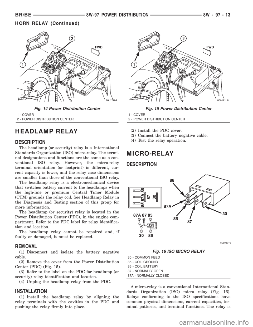
(2) Remove the cover from the Power Distribution
Center (PDC) (Fig. 15).
(3) Refer to the label on the PDC for headlamp (or
security) relay identification and location.
(4) Unplug the headlamp relay from the PDC.
INSTALLATION
(1) Install the headlamp relay by aligning the
relay terminals with the cavities in the PDC and
pushing the relay firmly into place.(2) Install the PDC cover.
(3) Connect the battery negative cable.
(4) Test the relay operation.
MICRO-RELAY
DESCRIPTION
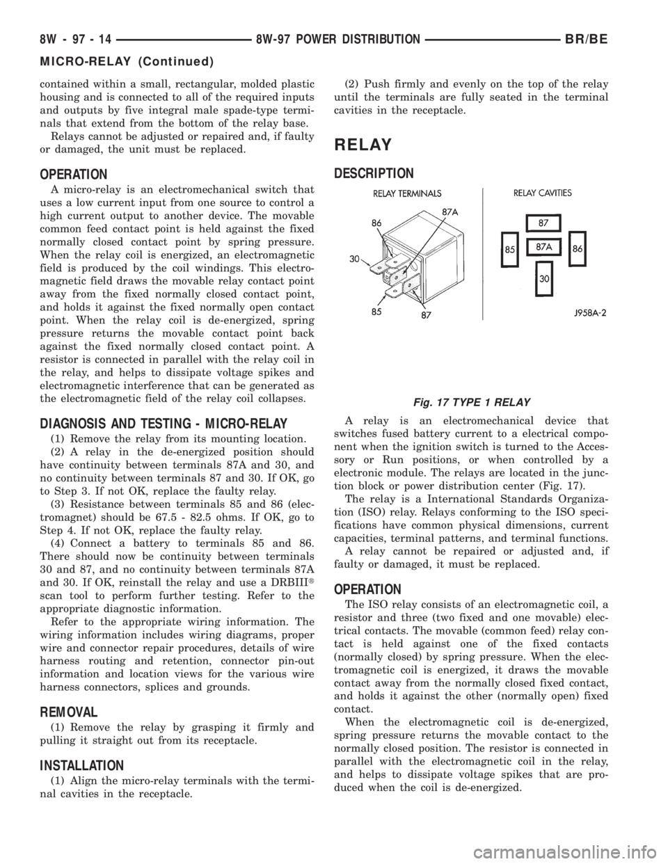
A micro-relay is a conventional International Stan-
dards Organization (ISO) micro relay (Fig. 16).
Relays conforming to the ISO specifications have
common physical dimensions, current capacities, ter-
minal patterns, and terminal functions. The relay is
Fig. 14 Power Distribution Center
1 - COVER
2 - POWER DISTRIBUTION CENTER
Fig. 15 Power Distribution Center
1 - COVER
2 - POWER DISTRIBUTION CENTER
Fig. 16 ISO MICRO RELAY
30 - COMMON FEED
85 - COIL GROUND
86 - COIL BATTERY
87 - NORMALLY OPEN
87A - NORMALLY CLOSED
BR/BE8W-97 POWER DISTRIBUTION 8W - 97 - 13
HORN RELAY (Continued)
Page 1073 of 2255
contained within a small, rectangular, molded plastic
housing and is connected to all of the required inputs
and outputs by five integral male spade-type termi-
nals that extend from the bottom of the relay base.
Relays cannot be adjusted or repaired and, if faulty
or damaged, the unit must be replaced.
OPERATION
A micro-relay is an electromechanical switch that
uses a low current input from one source to control a
high current output to another device. The movable
common feed contact point is held against the fixed
normally closed contact point by spring pressure.
When the relay coil is energized, an electromagnetic
field is produced by the coil windings. This electro-
magnetic field draws the movable relay contact point
away from the fixed normally closed contact point,
and holds it against the fixed normally open contact
point. When the relay coil is de-energized, spring
pressure returns the movable contact point back
against the fixed normally closed contact point. A
resistor is connected in parallel with the relay coil in
the relay, and helps to dissipate voltage spikes and
electromagnetic interference that can be generated as
the electromagnetic field of the relay coil collapses.
DIAGNOSIS AND TESTING - MICRO-RELAY
(1) Remove the relay from its mounting location.
(2) A relay in the de-energized position should
have continuity between terminals 87A and 30, and
no continuity between terminals 87 and 30. If OK, go
to Step 3. If not OK, replace the faulty relay.
(3) Resistance between terminals 85 and 86 (elec-
tromagnet) should be 67.5 - 82.5 ohms. If OK, go to
Step 4. If not OK, replace the faulty relay.
(4) Connect a battery to terminals 85 and 86.
There should now be continuity between terminals
30 and 87, and no continuity between terminals 87A
and 30. If OK, reinstall the relay and use a DRBIIIt
scan tool to perform further testing. Refer to the
appropriate diagnostic information.
Refer to the appropriate wiring information. The
wiring information includes wiring diagrams, proper
wire and connector repair procedures, details of wire
harness routing and retention, connector pin-out
information and location views for the various wire
harness connectors, splices and grounds.
REMOVAL
(1) Remove the relay by grasping it firmly and
pulling it straight out from its receptacle.
INSTALLATION
(1) Align the micro-relay terminals with the termi-
nal cavities in the receptacle.(2) Push firmly and evenly on the top of the relay
until the terminals are fully seated in the terminal
cavities in the receptacle.
RELAY
DESCRIPTION
A relay is an electromechanical device that
switches fused battery current to a electrical compo-
nent when the ignition switch is turned to the Acces-
sory or Run positions, or when controlled by a
electronic module. The relays are located in the junc-
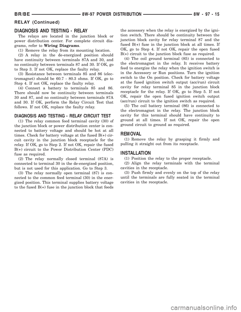
tion block or power distribution center (Fig. 17).
The relay is a International Standards Organiza-
tion (ISO) relay. Relays conforming to the ISO speci-
fications have common physical dimensions, current
capacities, terminal patterns, and terminal functions.
A relay cannot be repaired or adjusted and, if
faulty or damaged, it must be replaced.
OPERATION
The ISO relay consists of an electromagnetic coil, a
resistor and three (two fixed and one movable) elec-
trical contacts. The movable (common feed) relay con-
tact is held against one of the fixed contacts
(normally closed) by spring pressure. When the elec-
tromagnetic coil is energized, it draws the movable
contact away from the normally closed fixed contact,
and holds it against the other (normally open) fixed
contact.
When the electromagnetic coil is de-energized,
spring pressure returns the movable contact to the
normally closed position. The resistor is connected in
parallel with the electromagnetic coil in the relay,
and helps to dissipate voltage spikes that are pro-
duced when the coil is de-energized.
Fig. 17 TYPE 1 RELAY
8W - 97 - 14 8W-97 POWER DISTRIBUTIONBR/BE
MICRO-RELAY (Continued)
Page 1074 of 2255
DIAGNOSIS AND TESTING - RELAY
The relays are located in the junction block or
power distribution center. For complete circuit dia-
grams, refer toWiring Diagrams.
(1) Remove the relay from its mounting location.
(2) A relay in the de-energized position should
have continuity between terminals 87A and 30, and
no continuity between terminals 87 and 30. If OK, go
to Step 3. If not OK, replace the faulty relay.
(3) Resistance between terminals 85 and 86 (elec-
tromagnet) should be 60.7 - 80.3 ohms. If OK, go to
Step 4. If not OK, replace the faulty relay.
(4) Connect a battery to terminals 85 and 86.
There should now be continuity between terminals
30 and 87, and no continuity between terminals 87A
and 30. If OK, perform the Relay Circuit Test that
follows. If not OK, replace the faulty relay.
DIAGNOSIS AND TESTING - RELAY CIRCUIT TEST
(1) The relay common feed terminal cavity (30) of
the junction block or power distribution center is con-
nected to battery voltage and should be hot at all
times. Check for battery voltage at the fused B(+) cir-
cuit cavity in the junction block receptacle for the
relay. If OK, go to Step 2. If not OK, repair the fused
B(+) circuit to the Power Distribution Center (PDC)
fuse as required.
(2) The relay normally closed terminal (87A) is
connected to terminal 30 in the de-energized position,
but is not used for this application. Go to Step 3.
(3) The relay normally open terminal (87) is con-
nected to the common feed terminal (30) in the ener-
gized position. This terminal supplies battery voltage
to the fused B(+) fuse in the junction block that feedsthe accessory when the relay is energized by the igni-
tion switch. There should be continuity between the
junction block cavity for relay terminal 87 and the
fused B(+) fuse in the junction block at all times. If
OK, go to Step 4. If not OK, repair the open fused
B(+) circuit to the junction block fuse as required.
(4) The coil ground terminal (85) is connected to
the electromagnet in the relay. It receives battery
feed to energize the relay when the ignition switch is
in the Accessory or Run positions. Turn the ignition
switch to the On position. Check for battery voltage
at the fused ignition switch output (acc/run) circuit
cavity for relay terminal 85 in the junction block
receptacle for the relay. If OK, go to Step 5. If not
OK, repair the open fused ignition switch output
(acc/run) circuit to the ignition switch as required.
(5) The coil battery terminal (86) is connected to
the electromagnet in the relay. The junction block
cavity for this terminal should have continuity to
ground at all times. If not OK, repair the open
ground circuit to ground as required.
REMOVAL
(1) Remove the relay by grasping it firmly and
pulling it straight out from its receptacle.
INSTALLATION
(1) Position the relay to the proper receptacle.
(2) Align the relay terminals with the terminal
cavities in the receptacle.
(3) Push firmly and evenly on the top of the relay
until the terminals are fully seated in the terminal
cavities in the receptacle.
BR/BE8W-97 POWER DISTRIBUTION 8W - 97 - 15
RELAY (Continued)
Page 1075 of 2255

Page 1076 of 2255
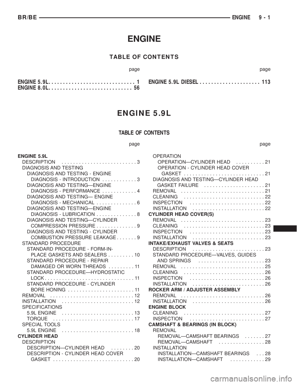
ENGINE
TABLE OF CONTENTS
page page
ENGINE 5.9L.............................. 1
ENGINE 8.0L............................. 56ENGINE 5.9L DIESEL..................... 113
ENGINE 5.9L
TABLE OF CONTENTS
page page
ENGINE 5.9L
DESCRIPTION..........................3
DIAGNOSIS AND TESTING
DIAGNOSIS AND TESTING - ENGINE
DIAGNOSIS - INTRODUCTION............3
DIAGNOSIS AND TESTINGÐENGINE
DIAGNOSIS - PERFORMANCE............4
DIAGNOSIS AND TESTINGÐ ENGINE
DIAGNOSIS - MECHANICAL..............6
DIAGNOSIS AND TESTINGÐENGINE
DIAGNOSIS - LUBRICATION..............8
DIAGNOSIS AND TESTINGÐCYLINDER
COMPRESSION PRESSURE..............9
DIAGNOSIS AND TESTING - CYLINDER
COMBUSTION PRESSURE LEAKAGE.......9
STANDARD PROCEDURE
STANDARD PROCEDURE - FORM-IN-
PLACE GASKETS AND SEALERS.........10
STANDARD PROCEDURE - REPAIR
DAMAGED OR WORN THREADS.........11
STANDARD PROCEDUREÐHYDROSTATIC
LOCK...............................11
STANDARD PROCEDURE - CYLINDER
BORE HONING.......................11
REMOVAL.............................12
INSTALLATION.........................12
SPECIFICATIONS
5.9L ENGINE.........................13
TORQUE............................17
SPECIAL TOOLS
5.9L ENGINE.........................18
CYLINDER HEAD
DESCRIPTION
DESCRIPTIONÐCYLINDER HEAD........20
DESCRIPTION - CYLINDER HEAD COVER
GASKET............................20OPERATION
OPERATIONÐCYLINDER HEAD..........21
OPERATION - CYLINDER HEAD COVER
GASKET............................21
DIAGNOSIS AND TESTINGÐCYLINDER HEAD
GASKET FAILURE.....................21
REMOVAL.............................21
CLEANING............................22
INSPECTION..........................22
INSTALLATION.........................22
CYLINDER HEAD COVER(S)
REMOVAL.............................23
CLEANING............................23
INSPECTION..........................23
INSTALLATION.........................23
INTAKE/EXHAUST VALVES & SEATS
DESCRIPTION.........................23
STANDARD PROCEDUREÐVALVES, GUIDES
AND SPRINGS.......................23
REMOVAL.............................25
CLEANING............................26
INSPECTION..........................26
INSTALLATION.........................26
ROCKER ARM / ADJUSTER ASSEMBLY
REMOVAL.............................26
INSTALLATION.........................26
ENGINE BLOCK
CLEANING............................27
INSPECTION..........................27
CAMSHAFT & BEARINGS (IN BLOCK)
REMOVAL
REMOVALÐCAMSHAFT BEARINGS.......27
REMOVALÐCAMSHAFT................28
INSTALLATION
INSTALLATIONÐCAMSHAFT BEARINGS . . . 28
INSTALLATIONÐCAMSHAFT............29
BR/BEENGINE 9 - 1
Page 1077 of 2255
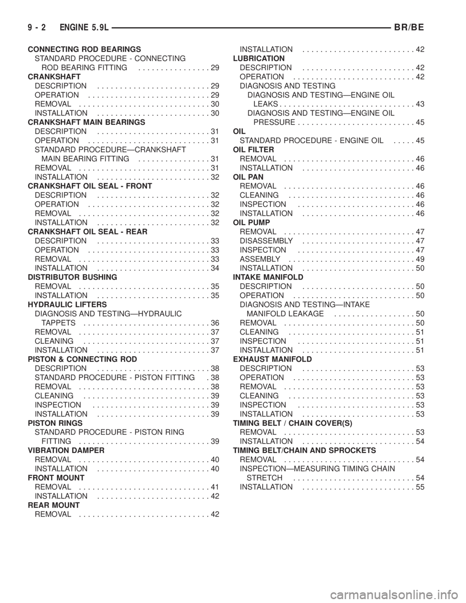
CONNECTING ROD BEARINGS
STANDARD PROCEDURE - CONNECTING
ROD BEARING FITTING................29
CRANKSHAFT
DESCRIPTION.........................29
OPERATION...........................29
REMOVAL.............................30
INSTALLATION.........................30
CRANKSHAFT MAIN BEARINGS
DESCRIPTION.........................31
OPERATION...........................31
STANDARD PROCEDUREÐCRANKSHAFT
MAIN BEARING FITTING................31
REMOVAL.............................31
INSTALLATION.........................32
CRANKSHAFT OIL SEAL - FRONT
DESCRIPTION.........................32
OPERATION...........................32
REMOVAL.............................32
INSTALLATION.........................32
CRANKSHAFT OIL SEAL - REAR
DESCRIPTION.........................33
OPERATION...........................33
REMOVAL.............................33
INSTALLATION.........................34
DISTRIBUTOR BUSHING
REMOVAL.............................35
INSTALLATION.........................35
HYDRAULIC LIFTERS
DIAGNOSIS AND TESTINGÐHYDRAULIC
TAPPETS............................36
REMOVAL.............................37
CLEANING............................37
INSTALLATION.........................37
PISTON & CONNECTING ROD
DESCRIPTION.........................38
STANDARD PROCEDURE - PISTON FITTING . 38
REMOVAL.............................38
CLEANING............................39
INSPECTION..........................39
INSTALLATION.........................39
PISTON RINGS
STANDARD PROCEDURE - PISTON RING
FITTING.............................39
VIBRATION DAMPER
REMOVAL.............................40
INSTALLATION.........................40
FRONT MOUNT
REMOVAL.............................41
INSTALLATION.........................42
REAR MOUNT
REMOVAL.............................42INSTALLATION.........................42
LUBRICATION
DESCRIPTION.........................42
OPERATION...........................42
DIAGNOSIS AND TESTING
DIAGNOSIS AND TESTINGÐENGINE OIL
LEAKS..............................43
DIAGNOSIS AND TESTINGÐENGINE OIL
PRESSURE..........................45
OIL
STANDARD PROCEDURE - ENGINE OIL.....45
OIL FILTER
REMOVAL.............................46
INSTALLATION.........................46
OIL PAN
REMOVAL.............................46
CLEANING............................46
INSPECTION..........................46
INSTALLATION.........................46
OIL PUMP
REMOVAL.............................47
DISASSEMBLY.........................47
INSPECTION..........................47
ASSEMBLY............................49
INSTALLATION.........................50
INTAKE MANIFOLD
DESCRIPTION.........................50
OPERATION...........................50
DIAGNOSIS AND TESTINGÐINTAKE
MANIFOLD LEAKAGE..................50
REMOVAL.............................50
CLEANING............................51
INSPECTION..........................51
INSTALLATION.........................51
EXHAUST MANIFOLD
DESCRIPTION.........................53
OPERATION...........................53
REMOVAL.............................53
CLEANING............................53
INSPECTION..........................53
INSTALLATION.........................53
TIMING BELT / CHAIN COVER(S)
REMOVAL.............................53
INSTALLATION.........................54
TIMING BELT/CHAIN AND SPROCKETS
REMOVAL.............................54
INSPECTIONÐMEASURING TIMING CHAIN
STRETCH...........................54
INSTALLATION.........................55
9 - 2 ENGINE 5.9LBR/BE
Page 1078 of 2255
ENGINE 5.9L
DESCRIPTION
The 5.9 Liter (360 CID) eight-cylinder engine is a
V-Type lightweight, single cam, overhead valve
engine with hydraulic roller tappets. This engine is
designed for unleaded fuel.
The engine lubrication system consists of a rotor
type oil pump and a full flow oil filter.
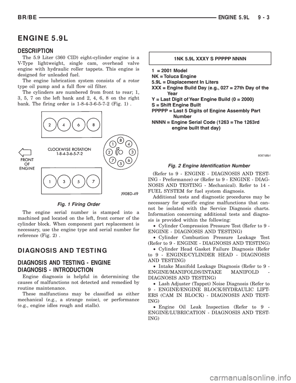
The cylinders are numbered from front to rear; 1,
3, 5, 7 on the left bank and 2, 4, 6, 8 on the right
bank. The firing order is 1-8-4-3-6-5-7-2 (Fig. 1) .
The engine serial number is stamped into a
machined pad located on the left, front corner of the
cylinder block. When component part replacement is
necessary, use the engine type and serial number for
reference (Fig. 2) .
DIAGNOSIS AND TESTING
DIAGNOSIS AND TESTING - ENGINE
DIAGNOSIS - INTRODUCTION
Engine diagnosis is helpful in determining the
causes of malfunctions not detected and remedied by
routine maintenance.
These malfunctions may be classified as either
mechanical (e.g., a strange noise), or performance
(e.g., engine idles rough and stalls).(Refer to 9 - ENGINE - DIAGNOSIS AND TEST-
ING - Preformance) or (Refer to 9 - ENGINE - DIAG-
NOSIS AND TESTING - Mechanical). Refer to 14 -
FUEL SYSTEM for fuel system diagnosis.
Additional tests and diagnostic procedures may be
necessary for specific engine malfunctions that can-
not be isolated with the Service Diagnosis charts.
Information concerning additional tests and diagno-
sis is provided within the following:
²Cylinder Compression Pressure Test (Refer to 9 -
ENGINE - DIAGNOSIS AND TESTING)
²Cylinder Combustion Pressure Leakage Test
(Refer to 9 - ENGINE - DIAGNOSIS AND TESTING)
²Cylinder Head Gasket Failure Diagnosis (Refer
to 9 - ENGINE/CYLINDER HEAD - DIAGNOSIS
AND TESTING)
²Intake Manifold Leakage Diagnosis (Refer to 9 -
ENGINE/MANIFOLDS/INTAKE MANIFOLD -
DIAGNOSIS AND TESTING)
²Lash Adjuster (Tappet) Noise Diagnosis (Refer to
9 - ENGINE/ENGINE BLOCK/HYDRAULIC LIFT-
ERS (CAM IN BLOCK) - DIAGNOSIS AND TEST-
ING)
²Engine Oil Leak Inspection (Refer to 9 -
ENGINE/LUBRICATION - DIAGNOSIS AND TEST-
ING)
Fig. 1 Firing Order
Fig. 2 Engine Identification Number
BR/BEENGINE 5.9L 9 - 3
Page 1079 of 2255
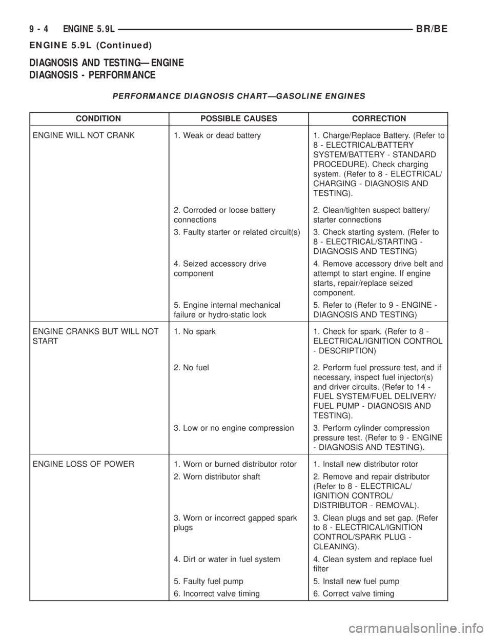
DIAGNOSIS AND TESTINGÐENGINE
DIAGNOSIS - PERFORMANCE
PERFORMANCE DIAGNOSIS CHARTÐGASOLINE ENGINES
CONDITION POSSIBLE CAUSES CORRECTION
ENGINE WILL NOT CRANK 1. Weak or dead battery 1. Charge/Replace Battery. (Refer to
8 - ELECTRICAL/BATTERY
SYSTEM/BATTERY - STANDARD
PROCEDURE). Check charging
system. (Refer to 8 - ELECTRICAL/
CHARGING - DIAGNOSIS AND
TESTING).
2. Corroded or loose battery
connections2. Clean/tighten suspect battery/
starter connections
3. Faulty starter or related circuit(s) 3. Check starting system. (Refer to
8 - ELECTRICAL/STARTING -
DIAGNOSIS AND TESTING)
4. Seized accessory drive
component4. Remove accessory drive belt and
attempt to start engine. If engine
starts, repair/replace seized
component.
5. Engine internal mechanical
failure or hydro-static lock5. Refer to (Refer to 9 - ENGINE -
DIAGNOSIS AND TESTING)
ENGINE CRANKS BUT WILL NOT
START1. No spark 1. Check for spark. (Refer to 8 -
ELECTRICAL/IGNITION CONTROL
- DESCRIPTION)
2. No fuel 2. Perform fuel pressure test, and if
necessary, inspect fuel injector(s)
and driver circuits. (Refer to 14 -
FUEL SYSTEM/FUEL DELIVERY/
FUEL PUMP - DIAGNOSIS AND
TESTING).
3. Low or no engine compression 3. Perform cylinder compression
pressure test. (Refer to 9 - ENGINE
- DIAGNOSIS AND TESTING).
ENGINE LOSS OF POWER 1. Worn or burned distributor rotor 1. Install new distributor rotor
2. Worn distributor shaft 2. Remove and repair distributor
(Refer to 8 - ELECTRICAL/
IGNITION CONTROL/
DISTRIBUTOR - REMOVAL).
3. Worn or incorrect gapped spark
plugs3. Clean plugs and set gap. (Refer
to 8 - ELECTRICAL/IGNITION
CONTROL/SPARK PLUG -
CLEANING).
4. Dirt or water in fuel system 4. Clean system and replace fuel
filter
5. Faulty fuel pump 5. Install new fuel pump
6. Incorrect valve timing 6. Correct valve timing
9 - 4 ENGINE 5.9LBR/BE
ENGINE 5.9L (Continued)
Page 1080 of 2255
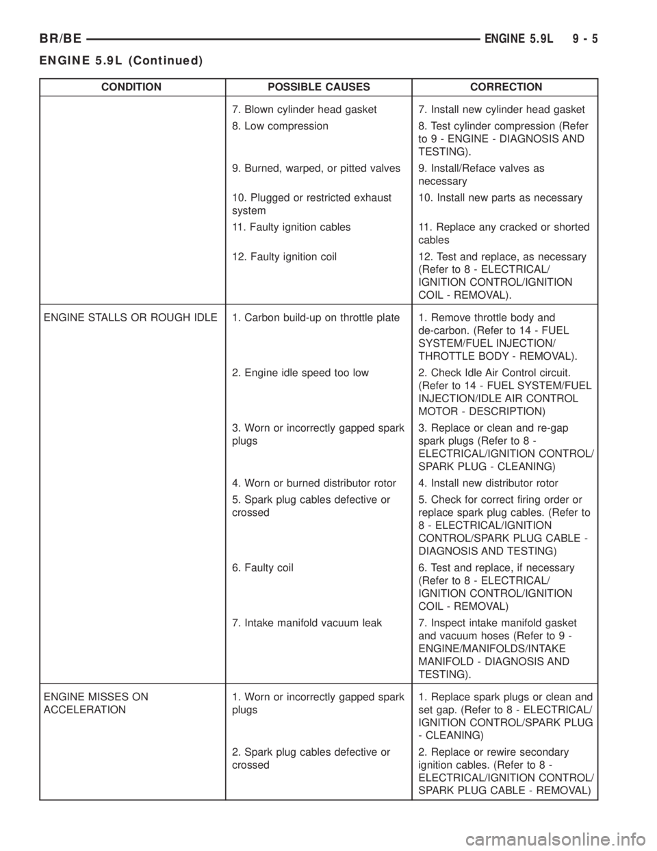
CONDITION POSSIBLE CAUSES CORRECTION
7. Blown cylinder head gasket 7. Install new cylinder head gasket
8. Low compression 8. Test cylinder compression (Refer
to 9 - ENGINE - DIAGNOSIS AND
TESTING).
9. Burned, warped, or pitted valves 9. Install/Reface valves as
necessary
10. Plugged or restricted exhaust
system10. Install new parts as necessary
11. Faulty ignition cables 11. Replace any cracked or shorted
cables
12. Faulty ignition coil 12. Test and replace, as necessary
(Refer to 8 - ELECTRICAL/
IGNITION CONTROL/IGNITION
COIL - REMOVAL).
ENGINE STALLS OR ROUGH IDLE 1. Carbon build-up on throttle plate 1. Remove throttle body and
de-carbon. (Refer to 14 - FUEL
SYSTEM/FUEL INJECTION/
THROTTLE BODY - REMOVAL).
2. Engine idle speed too low 2. Check Idle Air Control circuit.
(Refer to 14 - FUEL SYSTEM/FUEL
INJECTION/IDLE AIR CONTROL
MOTOR - DESCRIPTION)
3. Worn or incorrectly gapped spark
plugs3. Replace or clean and re-gap
spark plugs (Refer to 8 -
ELECTRICAL/IGNITION CONTROL/
SPARK PLUG - CLEANING)
4. Worn or burned distributor rotor 4. Install new distributor rotor
5. Spark plug cables defective or
crossed5. Check for correct firing order or
replace spark plug cables. (Refer to
8 - ELECTRICAL/IGNITION
CONTROL/SPARK PLUG CABLE -
DIAGNOSIS AND TESTING)
6. Faulty coil 6. Test and replace, if necessary
(Refer to 8 - ELECTRICAL/
IGNITION CONTROL/IGNITION
COIL - REMOVAL)
7. Intake manifold vacuum leak 7. Inspect intake manifold gasket
and vacuum hoses (Refer to 9 -
ENGINE/MANIFOLDS/INTAKE
MANIFOLD - DIAGNOSIS AND
TESTING).
ENGINE MISSES ON
ACCELERATION1. Worn or incorrectly gapped spark
plugs1. Replace spark plugs or clean and
set gap. (Refer to 8 - ELECTRICAL/
IGNITION CONTROL/SPARK PLUG
- CLEANING)
2. Spark plug cables defective or
crossed2. Replace or rewire secondary
ignition cables. (Refer to 8 -
ELECTRICAL/IGNITION CONTROL/
SPARK PLUG CABLE - REMOVAL)
BR/BEENGINE 5.9L 9 - 5
ENGINE 5.9L (Continued)