DODGE RAM 2002 Service Repair Manual
Manufacturer: DODGE, Model Year: 2002, Model line: RAM, Model: DODGE RAM 2002Pages: 2255, PDF Size: 62.07 MB
Page 1291 of 2255
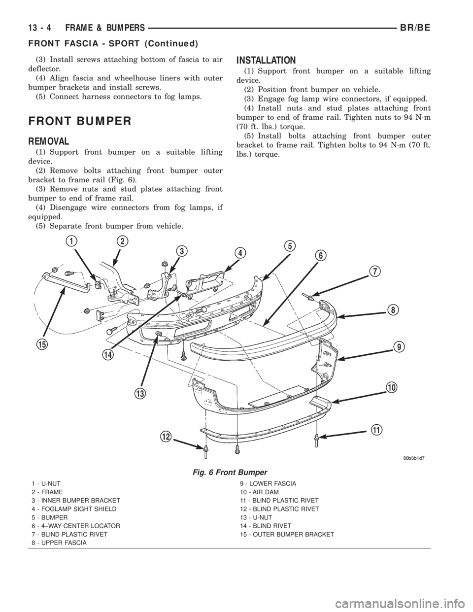
(3) Install screws attaching bottom of fascia to air
deflector.
(4) Align fascia and wheelhouse liners with outer
bumper brackets and install screws.
(5) Connect harness connectors to fog lamps.
FRONT BUMPER
REMOVAL
(1) Support front bumper on a suitable lifting
device.
(2) Remove bolts attaching front bumper outer
bracket to frame rail (Fig. 6).
(3) Remove nuts and stud plates attaching front
bumper to end of frame rail.
(4) Disengage wire connectors from fog lamps, if
equipped.
(5) Separate front bumper from vehicle.
INSTALLATION
(1) Support front bumper on a suitable lifting
device.
(2) Position front bumper on vehicle.
(3) Engage fog lamp wire connectors, if equipped.
(4) Install nuts and stud plates attaching front
bumper to end of frame rail. Tighten nuts to 94 N´m
(70 ft. lbs.) torque.
(5) Install bolts attaching front bumper outer
bracket to frame rail. Tighten bolts to 94 N´m (70 ft.
lbs.) torque.
Fig. 6 Front Bumper
1 - U-NUT
2 - FRAME
3 - INNER BUMPER BRACKET
4 - FOGLAMP SIGHT SHIELD
5 - BUMPER
6 - 4±WAY CENTER LOCATOR
7 - BLIND PLASTIC RIVET
8 - UPPER FASCIA9 - LOWER FASCIA
10 - AIR DAM
11 - BLIND PLASTIC RIVET
12 - BLIND PLASTIC RIVET
13 - U-NUT
14 - BLIND RIVET
15 - OUTER BUMPER BRACKET
13 - 4 FRAME & BUMPERSBR/BE
FRONT FASCIA - SPORT (Continued)
Page 1292 of 2255
FRONT BUMPER - SPORT
REMOVAL
(1) Disconnect wire connectors from fog lamps.
(2) Remove screws attaching fascia and outer
bumper brackets to wheelhouse liners.
(3) Remove screws and push-in fasteners attaching
bottom of fascia to air deflector.
(4) Support bumper on a suitable lifting device.
(5) Remove nuts attaching bumper to inner
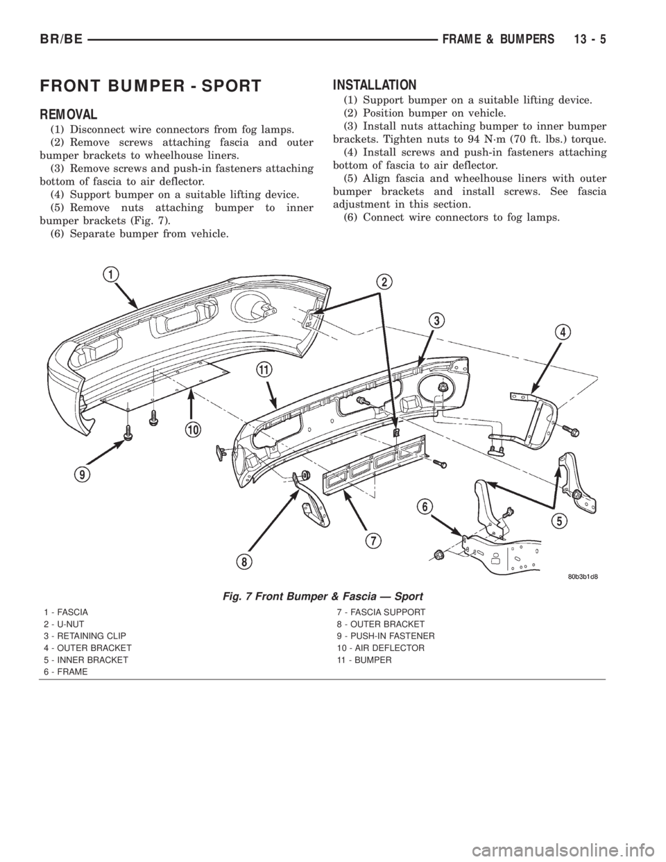
bumper brackets (Fig. 7).
(6) Separate bumper from vehicle.
INSTALLATION
(1) Support bumper on a suitable lifting device.
(2) Position bumper on vehicle.
(3) Install nuts attaching bumper to inner bumper
brackets. Tighten nuts to 94 N´m (70 ft. lbs.) torque.
(4) Install screws and push-in fasteners attaching
bottom of fascia to air deflector.
(5) Align fascia and wheelhouse liners with outer
bumper brackets and install screws. See fascia
adjustment in this section.
(6) Connect wire connectors to fog lamps.
Fig. 7 Front Bumper & Fascia Ð Sport
1 - FASCIA
2 - U-NUT
3 - RETAINING CLIP
4 - OUTER BRACKET
5 - INNER BRACKET
6 - FRAME7 - FASCIA SUPPORT
8 - OUTER BRACKET
9 - PUSH-IN FASTENER
10 - AIR DEFLECTOR
11 - BUMPER
BR/BEFRAME & BUMPERS 13 - 5
Page 1293 of 2255
REAR BUMPER
REMOVAL
(1) Support rear bumper on a suitable lifting
device.
(2) Remove nuts attaching rear bumper to inner
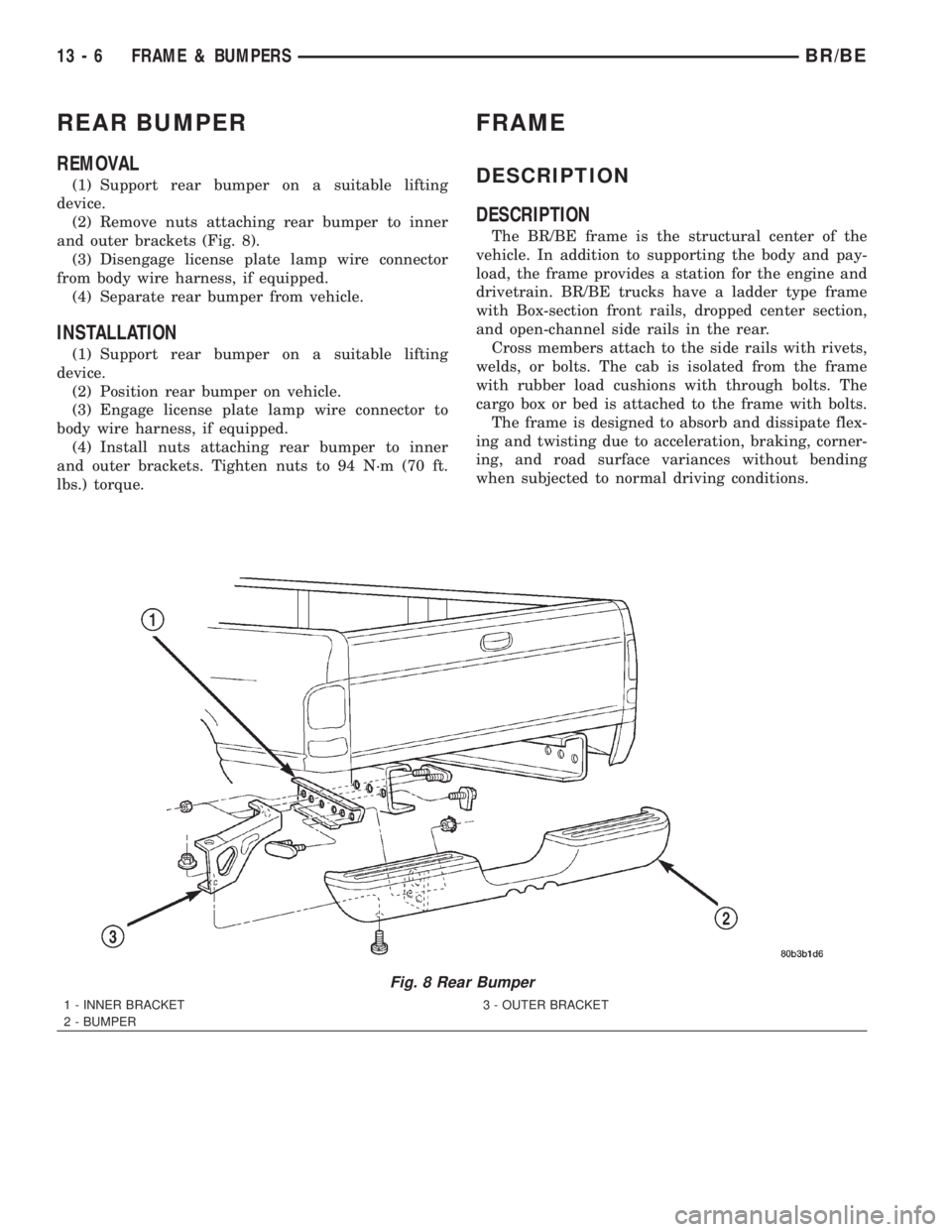
and outer brackets (Fig. 8).
(3) Disengage license plate lamp wire connector
from body wire harness, if equipped.
(4) Separate rear bumper from vehicle.
INSTALLATION
(1) Support rear bumper on a suitable lifting
device.
(2) Position rear bumper on vehicle.
(3) Engage license plate lamp wire connector to
body wire harness, if equipped.
(4) Install nuts attaching rear bumper to inner
and outer brackets. Tighten nuts to 94 N´m (70 ft.
lbs.) torque.
FRAME
DESCRIPTION
DESCRIPTION
The BR/BE frame is the structural center of the
vehicle. In addition to supporting the body and pay-
load, the frame provides a station for the engine and
drivetrain. BR/BE trucks have a ladder type frame
with Box-section front rails, dropped center section,
and open-channel side rails in the rear.
Cross members attach to the side rails with rivets,
welds, or bolts. The cab is isolated from the frame
with rubber load cushions with through bolts. The
cargo box or bed is attached to the frame with bolts.
The frame is designed to absorb and dissipate flex-
ing and twisting due to acceleration, braking, corner-
ing, and road surface variances without bending
when subjected to normal driving conditions.
Fig. 8 Rear Bumper
1 - INNER BRACKET
2 - BUMPER3 - OUTER BRACKET
13 - 6 FRAME & BUMPERSBR/BE
Page 1294 of 2255
FRAME SERVICE
SAFETY PRECAUTIONS AND WARNINGS
WARNING: USE EYE PROTECTION WHEN GRIND-
ING OR WELDING METAL, SERIOUS EYE INJURY
CAN RESULT. BEFORE PROCEEDING WITH FRAME
REPAIR INVOLVING GRINDING OR WELDING, VER-
IFY THAT VEHICLE FUEL SYSTEM IS NOT LEAKING
OR IN CONTACT WITH REPAIR AREA, PERSONAL
INJURY CAN RESULT. DO NOT ALLOW OPEN
FLAME TO CONTACT PLASTIC BODY PANELS.
FIRE OR EXPLOSION CAN RESULT. WHEN
WELDED FRAME COMPONENTS ARE REPLACED,
100% PENETRATION WELD MUST BE ACHIEVED
DURING INSTALLATION. IF NOT, DANGEROUS
OPERATING CONDITIONS CAN RESULT. STAND
CLEAR OF CABLES OR CHAINS ON PULLING
EQUIPMENT DURING FRAME STRAIGHTENING
OPERATIONS, PERSONAL INJURY CAN RESULT.
DO NOT VENTURE UNDER A HOISTED VEHICLE
THAT IS NOT SUPPORTED ON SAFETY STANDS,
PERSONAL INJURY CAN RESULT.
CAUTION: Do not reuse damaged fasteners, quality
of repair would be suspect. Do not drill holes in top
or bottom frame rail flanges, frame rail failure can
result. Do Not use softer than Grade 5 bolts to
replace production fasteners, loosening or failure
can result. When using heat to straighten frame
components do not exceed 566ÉC (1050ÉF), metal
fatigue can result. Welding the joints around riveted
cross members and frame side rails can weaken
frame.
FRAME STRAIGHTENING
When necessary, a conventional frame that is bent
or twisted can be straightened by application of heat.
The temperature must not exceed 566ÉC (1050ÉF).
The metal will have a dull red glow at the desired
temperature. Excessive heat will decrease the
strength of the metal and result in a weakened
frame.
Welding the joints around riveted cross members
and frame side rails is not recommended.
A straightening repair process should be limited to
frame members that are not severely damaged. The
replacement bolts, nuts and rivets that are used to
join the frame members should conform to the same
specifications as the original bolts, nuts and rivets.
FRAME REPAIRS
DRILLING HOLES
Do not drill holes in frame side rail top and bottom
flanges, metal fatigue can result causing frame fail-
ure. Holes drilled in the side of the frame rail must
be at least 38 mm (1.5 in.) from the top and bottom
flanges.
Additional drill holes should be located away from
existing holes.
WELDING
Use MIG, TIG or arc welding equipment to repair
welded frame components.
Frame components that have been damaged should
be inspected for cracks before returning the vehicle
to use. If cracks are found in accessible frame com-
ponents perform the following procedures.
(1) Drill a hole at each end of the crack with a 3
mm (O.125 in.) diameter drill bit.
(2) Using a suitable die grinder with 3 inch cut off
wheel, V-groove the crack to allow 100% weld pene-
tration.
(3) Weld the crack.
(4) If necessary when a side rail is repaired, grind
the weld smooth and install a reinforcement channel
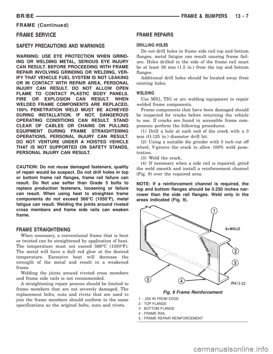
(Fig. 9) over the repaired area.
NOTE: If a reinforcement channel is required, the
top and bottom flanges should be 0.250 inches nar-
rower than the side rail flanges. Weld only in the
areas indicated (Fig. 9).
Fig. 9 Frame Reinforcement
1 - .250 IN FROM EDGE
2 - TOP FLANGE
3 - BOTTOM FLANGE
4 - FRAME RAIL
5 - FRAME REPAIR REINFORCEMENT
BR/BEFRAME & BUMPERS 13 - 7
FRAME (Continued)
Page 1295 of 2255
FRAME FASTENERS
Bolts, nuts and rivets can be used to repair frames
or to install a reinforcement section on the frame.
Bolts can be used in place of rivets. When replacing
rivets with bolts, install the next larger size diameter
bolt to assure proper fit. If necessary, ream the hole
out just enough to sufficiently receive the bolt.
Conical-type washers are preferred over the split-
ring type lock washers. Normally, grade-5 bolts are
adequate for frame repair.Grade-3 bolts or softer
should not be used.Tightening bolts/nuts with thecorrect torque, refer to the Introduction Group at the
front of this manual for tightening information.
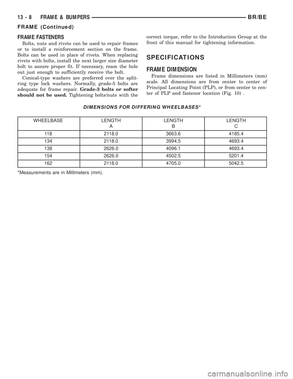
SPECIFICATIONS
FRAME DIMENSION
Frame dimensions are listed in Millimeters (mm)
scale. All dimensions are from center to center of
Principal Locating Point (PLP), or from center to cen-
ter of PLP and fastener location (Fig. 10) .
DIMENSIONS FOR DIFFERING WHEELBASES*
WHEELBASE LENGTH
ALENGTH
BLENGTH
C
118 2118.0 3663.6 4185.4
134 2118.0 3994.5 4693.4
138 2626.0 4096.1 4693.4
154 2626.0 4502.5 5201.4
162 2118.0 4705.0 5042.5
*Measurements are in Millimeters (mm).
13 - 8 FRAME & BUMPERSBR/BE
FRAME (Continued)
Page 1296 of 2255
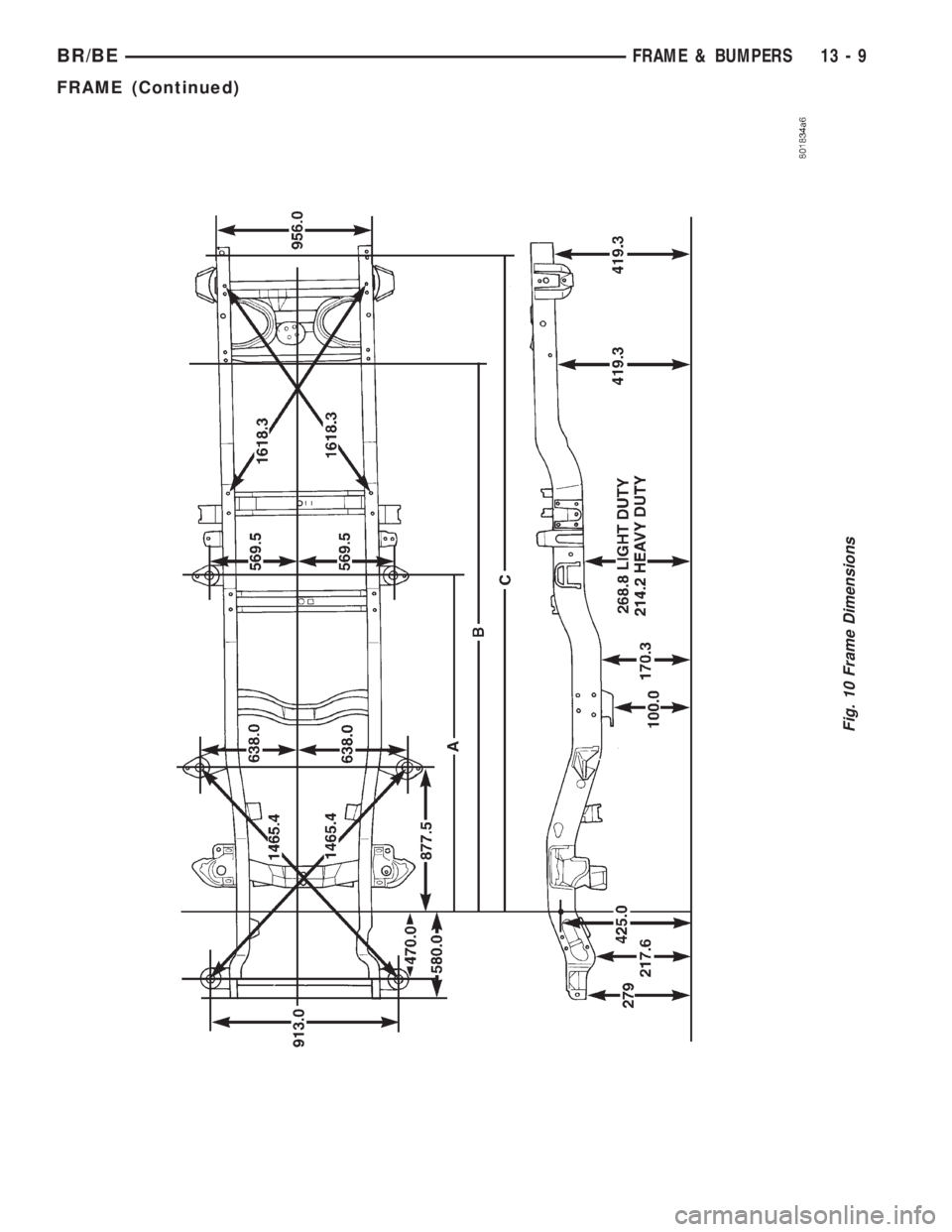
Fig. 10 Frame Dimensions
BR/BEFRAME & BUMPERS 13 - 9
FRAME (Continued)
Page 1297 of 2255
CAB CHASSIS ADAPTER
BRACKET
REMOVAL
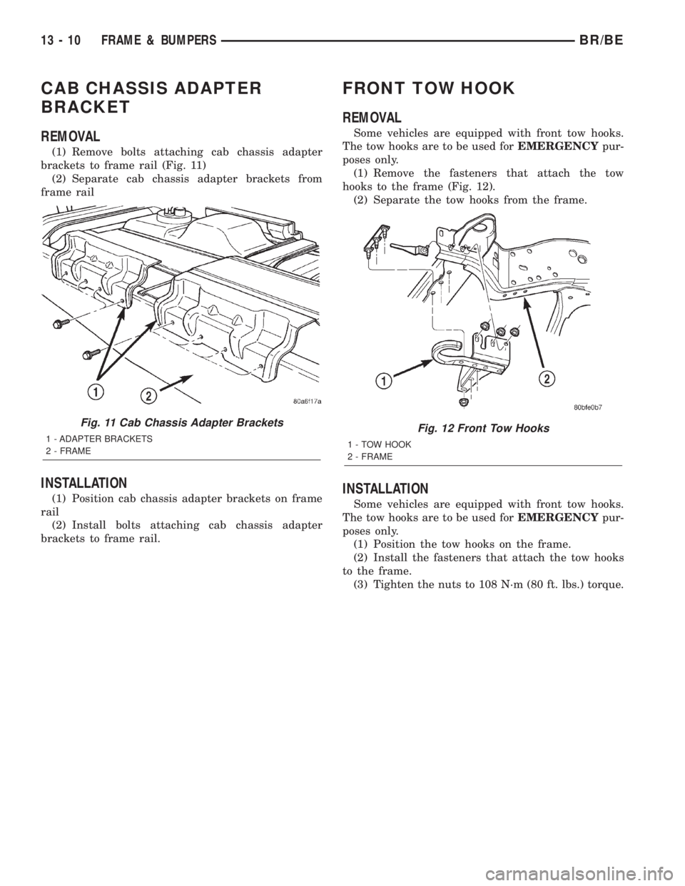
(1) Remove bolts attaching cab chassis adapter
brackets to frame rail (Fig. 11)
(2) Separate cab chassis adapter brackets from
frame rail
INSTALLATION
(1) Position cab chassis adapter brackets on frame
rail
(2) Install bolts attaching cab chassis adapter
brackets to frame rail.
FRONT TOW HOOK
REMOVAL
Some vehicles are equipped with front tow hooks.
The tow hooks are to be used forEMERGENCYpur-
poses only.
(1) Remove the fasteners that attach the tow
hooks to the frame (Fig. 12).
(2) Separate the tow hooks from the frame.
INSTALLATION
Some vehicles are equipped with front tow hooks.
The tow hooks are to be used forEMERGENCYpur-
poses only.
(1) Position the tow hooks on the frame.
(2) Install the fasteners that attach the tow hooks
to the frame.
(3) Tighten the nuts to 108 N´m (80 ft. lbs.) torque.
Fig. 11 Cab Chassis Adapter Brackets
1 - ADAPTER BRACKETS
2 - FRAMEFig. 12 Front Tow Hooks
1 - TOW HOOK
2 - FRAME
13 - 10 FRAME & BUMPERSBR/BE
Page 1298 of 2255
TRAILER HITCH
REMOVAL
(1) Support trailer hitch on a suitable lifting
device.
(2) Remove fasteners attaching trailer wiring con-
nector to trailer hitch, if equipped.
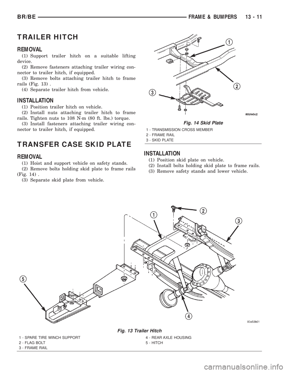
(3) Remove bolts attaching trailer hitch to frame
rails (Fig. 13) .
(4) Separate trailer hitch from vehicle.
INSTALLATION
(1) Position trailer hitch on vehicle.
(2) Install nuts attaching trailer hitch to frame
rails. Tighten nuts to 108 N´m (80 ft. lbs.) torque.
(3) Install fasteners attaching trailer wiring con-
nector to trailer hitch, if equipped.
TRANSFER CASE SKID PLATE
REMOVAL
(1) Hoist and support vehicle on safety stands.
(2) Remove bolts holding skid plate to frame rails
(Fig. 14) .
(3) Separate skid plate from vehicle.
INSTALLATION
(1) Position skid plate on vehicle.
(2) Install bolts holding skid plate to frame rails.
(3) Remove safety stands and lower vehicle.
Fig. 13 Trailer Hitch
1 - SPARE TIRE WINCH SUPPORT
2 - FLAG BOLT
3 - FRAME RAIL4 - REAR AXLE HOUSING
5 - HITCH
Fig. 14 Skid Plate
1 - TRANSMISSION CROSS MEMBER
2 - FRAME RAIL
3 - SKID PLATE
BR/BEFRAME & BUMPERS 13 - 11
Page 1299 of 2255

Page 1300 of 2255
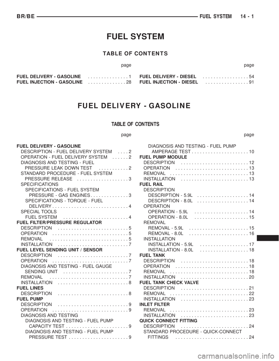
FUEL SYSTEM
TABLE OF CONTENTS
page page
FUEL DELIVERY - GASOLINE...............1
FUEL INJECTION - GASOLINE..............28FUEL DELIVERY - DIESEL.................54
FUEL INJECTION - DIESEL................91
FUEL DELIVERY - GASOLINE
TABLE OF CONTENTS
page page
FUEL DELIVERY - GASOLINE
DESCRIPTION - FUEL DELIVERY SYSTEM....2
OPERATION - FUEL DELIVERY SYSTEM......2
DIAGNOSIS AND TESTING - FUEL
PRESSURE LEAK DOWN TEST...........2
STANDARD PROCEDURE - FUEL SYSTEM
PRESSURE RELEASE...................3
SPECIFICATIONS
SPECIFICATIONS - FUEL SYSTEM
PRESSURE - GAS ENGINES..............3
SPECIFICATIONS - TORQUE - FUEL
DELIVERY............................4
SPECIAL TOOLS
FUEL SYSTEM........................4
FUEL FILTER/PRESSURE REGULATOR
DESCRIPTION..........................5
OPERATION............................5
REMOVAL.............................5
INSTALLATION..........................7
FUEL LEVEL SENDING UNIT / SENSOR
DESCRIPTION..........................7
OPERATION............................7
DIAGNOSIS AND TESTING - FUEL GAUGE
SENDING UNIT........................7
REMOVAL.............................7
INSTALLATION..........................8
FUEL LINES
DESCRIPTION..........................8
FUEL PUMP
DESCRIPTION..........................9
OPERATION............................9
DIAGNOSIS AND TESTING
DIAGNOSIS AND TESTING - FUEL PUMP
CAPACITY TEST.......................9
DIAGNOSIS AND TESTING - FUEL PUMP
PRESSURE TEST......................9DIAGNOSIS AND TESTING - FUEL PUMP
AMPERAGE TEST.....................10
FUEL PUMP MODULE
DESCRIPTION.........................12
OPERATION...........................13
REMOVAL.............................13
INSTALLATION.........................13
FUEL RAIL
DESCRIPTION
DESCRIPTION - 5.9L...................14
DESCRIPTION - 8.0L...................14
OPERATION
OPERATION - 5.9L....................14
OPERATION - 8.0L....................15
REMOVAL
REMOVAL - 5.9L......................15
REMOVAL - 8.0L......................16
INSTALLATION
INSTALLATION - 5.9L..................17
INSTALLATION - 8.0L..................18
FUEL TANK
DESCRIPTION.........................18
OPERATION...........................18
REMOVAL.............................18
INSTALLATION.........................20
FUEL TANK CHECK VALVE
DESCRIPTION.........................21
REMOVAL.............................22
INSTALLATION.........................23
INLET FILTER
REMOVAL.............................23
INSTALLATION.........................23
QUICK CONNECT FITTING
DESCRIPTION.........................24
STANDARD PROCEDURE - QUICK-CONNECT
FITTINGS...........................24
BR/BEFUEL SYSTEM 14 - 1