check engine DODGE RAM 2002 Service Repair Manual
[x] Cancel search | Manufacturer: DODGE, Model Year: 2002, Model line: RAM, Model: DODGE RAM 2002Pages: 2255, PDF Size: 62.07 MB
Page 1174 of 2255
holes and the oil drain-back passages in the cylinder
head, past the valve tappet area, and then returns to
the oil pan (Fig. 52).
DIAGNOSIS AND TESTING
DIAGNOSIS AND TESTINGÐENGINE OIL
LEAKS
Begin with a through visual inspection of the
engine, particularly at the area of the suspected leak.
If an oil leak source is not readily identifiable, the
following steps should be followed:
(1) Do not clean or degrease the engine at this
time because some solvents may cause rubber to
swell, temporarily stopping the leak.
(2) Add an oil-soluble dye (use as recommended by
manufacturer). Start the engine and let idle for
approximately 15 minutes. Check the oil dipstick to
be sure the dye is thoroughly mixed as indicated
with a bright yellow color under a black light source.
(3) Using a black light, inspect the entire engine
for fluorescent dye, particularly at the suspected area
of oil leak. If the oil leak is found and identified,
repair per service manual instructions.
(4) If dye is not observed, drive the vehicle at var-
ious speeds for approximately 24km (15 miles), and
repeat previous step.
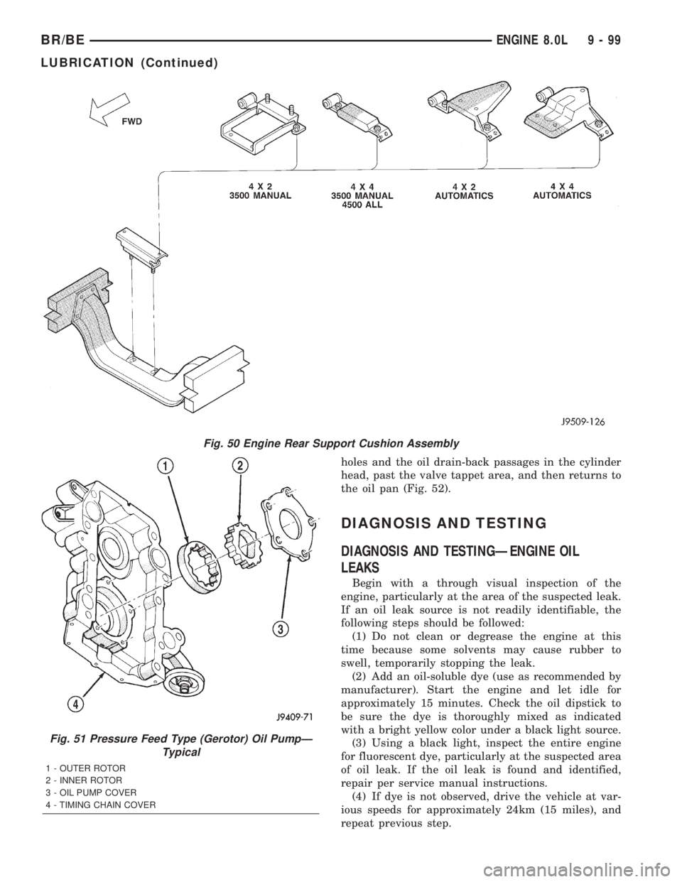
Fig. 50 Engine Rear Support Cushion Assembly
Fig. 51 Pressure Feed Type (Gerotor) Oil PumpÐ
Typical
1 - OUTER ROTOR
2 - INNER ROTOR
3 - OIL PUMP COVER
4 - TIMING CHAIN COVER
BR/BEENGINE 8.0L 9 - 99
LUBRICATION (Continued)
Page 1178 of 2255
(3) Drain engine oil.
(4) Remove left engine to transmission strut.
(5) Remove oil pan mounting bolts, pan and one-
piece gasket. The engine may have to be raised
slightly on 2WD vehicles.
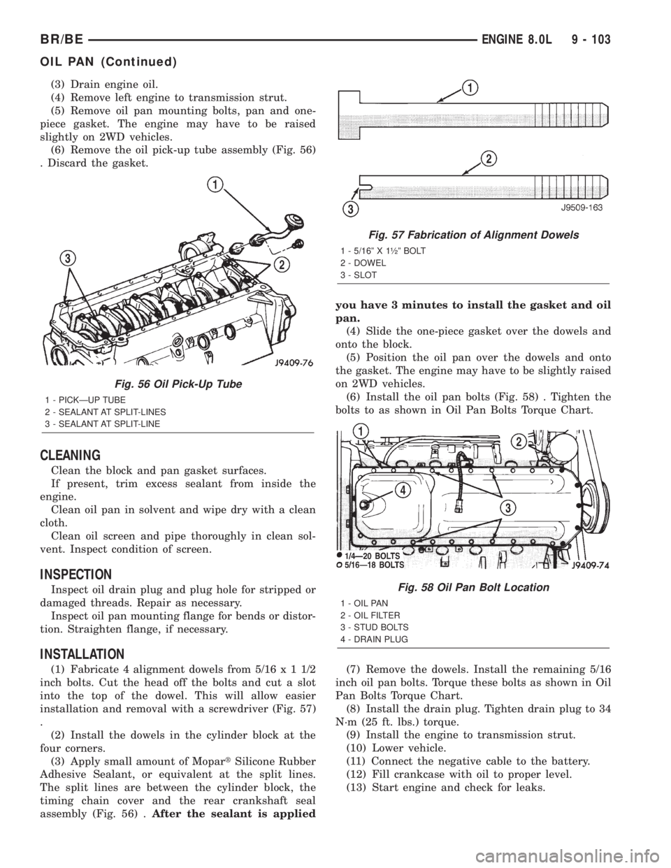
(6) Remove the oil pick-up tube assembly (Fig. 56)
. Discard the gasket.
CLEANING
Clean the block and pan gasket surfaces.
If present, trim excess sealant from inside the
engine.
Clean oil pan in solvent and wipe dry with a clean
cloth.
Clean oil screen and pipe thoroughly in clean sol-
vent. Inspect condition of screen.
INSPECTION
Inspect oil drain plug and plug hole for stripped or
damaged threads. Repair as necessary.
Inspect oil pan mounting flange for bends or distor-
tion. Straighten flange, if necessary.
INSTALLATION
(1) Fabricate 4 alignment dowels from 5/16x11/2
inch bolts. Cut the head off the bolts and cut a slot
into the top of the dowel. This will allow easier
installation and removal with a screwdriver (Fig. 57)
.
(2) Install the dowels in the cylinder block at the
four corners.
(3) Apply small amount of MopartSilicone Rubber
Adhesive Sealant, or equivalent at the split lines.
The split lines are between the cylinder block, the
timing chain cover and the rear crankshaft seal
assembly (Fig. 56) .After the sealant is appliedyou have 3 minutes to install the gasket and oil
pan.
(4) Slide the one-piece gasket over the dowels and
onto the block.
(5) Position the oil pan over the dowels and onto
the gasket. The engine may have to be slightly raised
on 2WD vehicles.
(6) Install the oil pan bolts (Fig. 58) . Tighten the
bolts to as shown in Oil Pan Bolts Torque Chart.
(7) Remove the dowels. Install the remaining 5/16
inch oil pan bolts. Torque these bolts as shown in Oil
Pan Bolts Torque Chart.
(8) Install the drain plug. Tighten drain plug to 34
N´m (25 ft. lbs.) torque.
(9) Install the engine to transmission strut.
(10) Lower vehicle.
(11) Connect the negative cable to the battery.
(12) Fill crankcase with oil to proper level.
(13) Start engine and check for leaks.
Fig. 56 Oil Pick-Up Tube
1 - PICKÐUP TUBE
2 - SEALANT AT SPLIT-LINES
3 - SEALANT AT SPLIT-LINE
Fig. 57 Fabrication of Alignment Dowels
1 - 5/16º X 1óº BOLT
2 - DOWEL
3 - SLOT
Fig. 58 Oil Pan Bolt Location
1 - OIL PAN
2 - OIL FILTER
3 - STUD BOLTS
4 - DRAIN PLUG
BR/BEENGINE 8.0L 9 - 103
OIL PAN (Continued)
Page 1179 of 2255
OIL PUMP
REMOVAL
(1) Remove the timing chain cover (Refer to 9 -
ENGINE/VALVE TIMING/TIMING BELT / CHAIN
COVER(S) - REMOVAL).
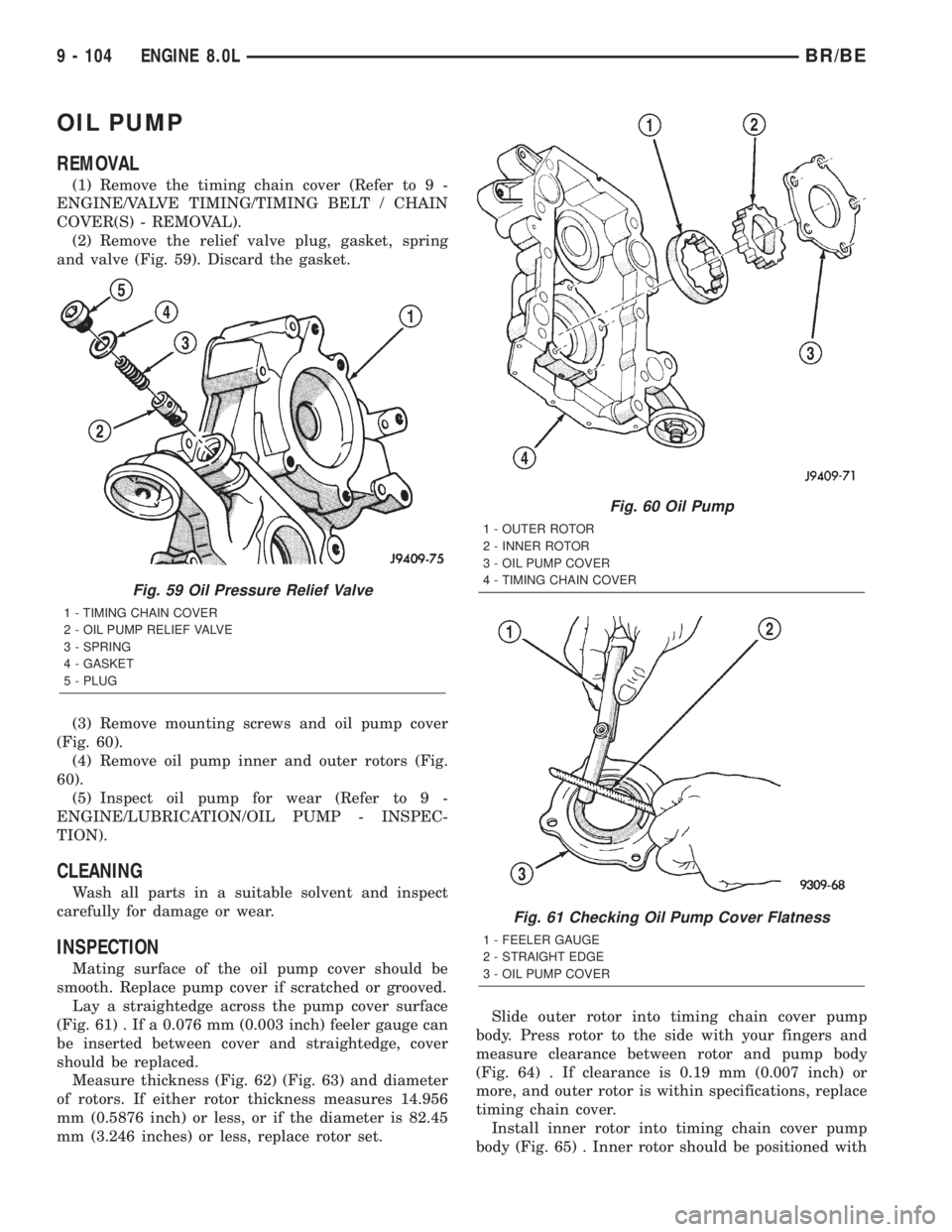
(2) Remove the relief valve plug, gasket, spring
and valve (Fig. 59). Discard the gasket.
(3) Remove mounting screws and oil pump cover
(Fig. 60).
(4) Remove oil pump inner and outer rotors (Fig.
60).
(5) Inspect oil pump for wear (Refer to 9 -
ENGINE/LUBRICATION/OIL PUMP - INSPEC-
TION).
CLEANING
Wash all parts in a suitable solvent and inspect
carefully for damage or wear.
INSPECTION
Mating surface of the oil pump cover should be
smooth. Replace pump cover if scratched or grooved.
Lay a straightedge across the pump cover surface
(Fig. 61) . If a 0.076 mm (0.003 inch) feeler gauge can
be inserted between cover and straightedge, cover
should be replaced.
Measure thickness (Fig. 62) (Fig. 63) and diameter
of rotors. If either rotor thickness measures 14.956
mm (0.5876 inch) or less, or if the diameter is 82.45
mm (3.246 inches) or less, replace rotor set.Slide outer rotor into timing chain cover pump
body. Press rotor to the side with your fingers and
measure clearance between rotor and pump body
(Fig. 64) . If clearance is 0.19 mm (0.007 inch) or
more, and outer rotor is within specifications, replace
timing chain cover.
Install inner rotor into timing chain cover pump
body (Fig. 65) . Inner rotor should be positioned with
Fig. 59 Oil Pressure Relief Valve
1 - TIMING CHAIN COVER
2 - OIL PUMP RELIEF VALVE
3 - SPRING
4 - GASKET
5 - PLUG
Fig. 60 Oil Pump
1 - OUTER ROTOR
2 - INNER ROTOR
3 - OIL PUMP COVER
4 - TIMING CHAIN COVER
Fig. 61 Checking Oil Pump Cover Flatness
1 - FEELER GAUGE
2 - STRAIGHT EDGE
3 - OIL PUMP COVER
9 - 104 ENGINE 8.0LBR/BE
Page 1183 of 2255
INSPECTION
Inspect manifold for cracks.
Inspect mating surfaces of manifold for flatness
with a straightedge.
INSTALLATION
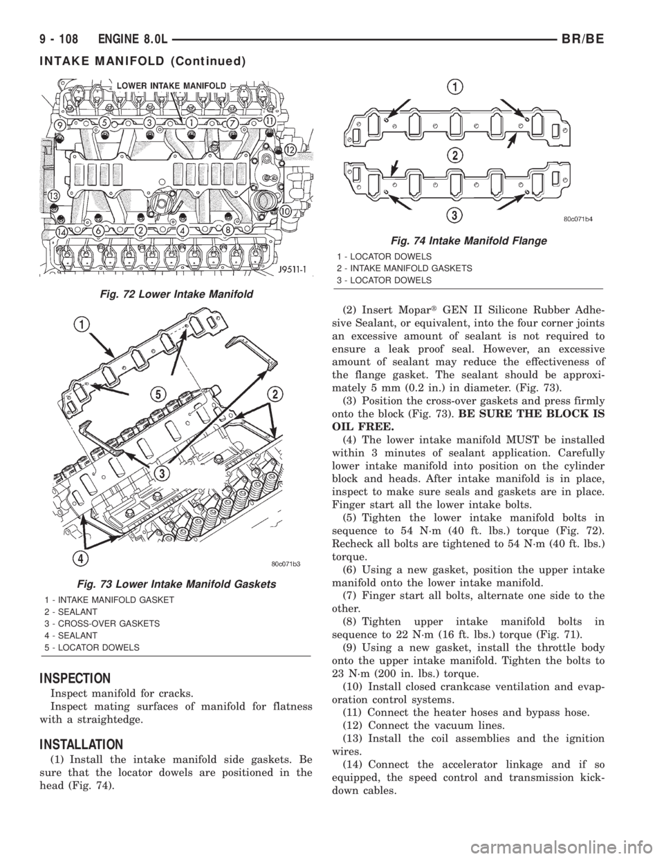
(1) Install the intake manifold side gaskets. Be
sure that the locator dowels are positioned in the
head (Fig. 74).(2) Insert MopartGEN II Silicone Rubber Adhe-
sive Sealant, or equivalent, into the four corner joints
an excessive amount of sealant is not required to
ensure a leak proof seal. However, an excessive
amount of sealant may reduce the effectiveness of
the flange gasket. The sealant should be approxi-
mately 5 mm (0.2 in.) in diameter. (Fig. 73).
(3) Position the cross-over gaskets and press firmly
onto the block (Fig. 73).BE SURE THE BLOCK IS
OIL FREE.
(4) The lower intake manifold MUST be installed
within 3 minutes of sealant application. Carefully
lower intake manifold into position on the cylinder
block and heads. After intake manifold is in place,
inspect to make sure seals and gaskets are in place.
Finger start all the lower intake bolts.
(5) Tighten the lower intake manifold bolts in
sequence to 54 N´m (40 ft. lbs.) torque (Fig. 72).
Recheck all bolts are tightened to 54 N´m (40 ft. lbs.)
torque.
(6) Using a new gasket, position the upper intake
manifold onto the lower intake manifold.
(7) Finger start all bolts, alternate one side to the
other.
(8) Tighten upper intake manifold bolts in
sequence to 22 N´m (16 ft. lbs.) torque (Fig. 71).
(9) Using a new gasket, install the throttle body
onto the upper intake manifold. Tighten the bolts to
23 N´m (200 in. lbs.) torque.
(10) Install closed crankcase ventilation and evap-
oration control systems.
(11) Connect the heater hoses and bypass hose.
(12) Connect the vacuum lines.
(13) Install the coil assemblies and the ignition
wires.
(14) Connect the accelerator linkage and if so
equipped, the speed control and transmission kick-
down cables.
Fig. 72 Lower Intake Manifold
Fig. 73 Lower Intake Manifold Gaskets
1 - INTAKE MANIFOLD GASKET
2 - SEALANT
3 - CROSS-OVER GASKETS
4 - SEALANT
5 - LOCATOR DOWELS
Fig. 74 Intake Manifold Flange
1 - LOCATOR DOWELS
2 - INTAKE MANIFOLD GASKETS
3 - LOCATOR DOWELS
9 - 108 ENGINE 8.0LBR/BE
INTAKE MANIFOLD (Continued)
Page 1184 of 2255
(15) Install the fuel lines (Refer to 14 - FUEL SYS-
TEM/FUEL DELIVERY/QUICK CONNECT FIT-
TING - STANDARD PROCEDURE).
(16) Using a new gasket, install the air cleaner
housing. Tighten the nuts to 11 N´m (96 in. lbs.)
torque. Install the air cleaner filter and cover.
(17) Install the A/C compressor (Refer to 24 -
HEATING & AIR CONDITIONING/PLUMBING/A/C
COMPRESSOR - INSTALLATION). Position the com-
pressor brace and install the bolts. Tighten the brace
bolts to 41 N´m (30 ft. lbs.) torque.
(18) Install the generator (Refer to 8 - ELECTRI-
CAL/CHARGING/GENERATOR - INSTALLATION).
Position the generator brace and install the bolts.
Tighten the brace bolts to 41 N´m (30 ft. lbs.) torque.
(19) Install the accessory drive belt (Refer to 7 -
COOLING/ACCESSORY DRIVE/DRIVE BELTS -
INSTALLATION).
(20) Fill cooling system (Refer to 7 - COOLING -
STANDARD PROCEDURE).
(21) Connect the negative cable to the battery.
(22) Start engine check for leaks.
EXHAUST MANIFOLD
DESCRIPTION
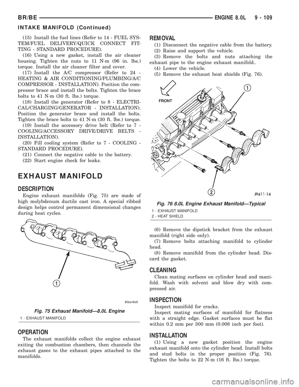
Engine exhaust manifolds (Fig. 75) are made of
high molybdenum ductile cast iron. A special ribbed
design helps control permanent dimensional changes
during heat cycles.
OPERATION
The exhaust manifolds collect the engine exhaust
exiting the combustion chambers, then channels the
exhaust gases to the exhaust pipes attached to the
manifolds.
REMOVAL
(1) Disconnect the negative cable from the battery.
(2) Raise and support the vehicle.
(3) Remove the bolts and nuts attaching the
exhaust pipe to the engine exhaust manifold..
(4) Lower the vehicle.
(5) Remove the exhaust heat shields (Fig. 76).
(6) Remove the dipstick bracket from the exhaust
manifold (right side only).
(7) Remove bolts attaching manifold to cylinder
head.
(8) Remove manifold from the cylinder head. Dis-
card the gasket.
CLEANING
Clean mating surfaces on cylinder head and mani-
fold. Wash with solvent and blow dry with com-
pressed air.
INSPECTION
Inspect manifold for cracks.
Inspect mating surfaces of manifold for flatness
with a straight edge. Gasket surfaces must be flat
within 0.2 mm per 300 mm (0.008 inch per foot).
INSTALLATION
(1) Using a new gasket position the engine
exhaust manifold onto the cylinder head. Install bolts
and stud bolts in the proper position (Fig. 76).
Tighten the bolts to 22 N´m (16 ft. lbs.) torque.
Fig. 75 Exhaust ManifoldÐ8.0L Engine
1 - EXHAUST MANIFOLD
Fig. 76 8.0L Engine Exhaust ManifoldÐTypical
1 - EXHAUST MANIFOLD
2 - HEAT SHIELD
BR/BEENGINE 8.0L 9 - 109
INTAKE MANIFOLD (Continued)
Page 1185 of 2255
(2) Install the dipstick bracket on to the exhaust
manifold (right side only).
(3) Position washers and exhaust heat shields onto
the manifold stud bolts (Fig. 76). Be sure the tabs on
the heat shields are hooked over the top of the
exhaust gasket. Install the nuts and tighten to 20
N´m (175 in. lbs.) torque.
(4) Raise and support the vehicle.
(5) Assemble exhaust pipe to manifold.
(6) Lower the vehicle.
(7) Connect the negative cable to the battery.
(8) Start engine check for leaks.
TIMING BELT / CHAIN
COVER(S)
REMOVAL
(1) Disconnect the negative cable from the battery.
(2) Drain cooling system (Refer to 7 - COOLING -
STANDARD PROCEDURE).
(3) Remove the serpentine belt (Refer to 7 - COOL-
ING/ACCESSORY DRIVE/DRIVE BELTS - REMOV-
AL).
(4) Remove fan and fan shroud (Refer to 7 -
COOLING/ENGINE/RADIATOR FAN - REMOVAL).
(5) Unbolt A/C compressor and set on top of
engine.
(6) Remove generator, air pump, and bracket
assembly.
(7) Remove water pump (Refer to 7 - COOLING/
ENGINE/WATER PUMP - REMOVAL).
(8) Remove damper bolt and washer.
(9) Using Special Tool 1026 3-Jaw Puller remove
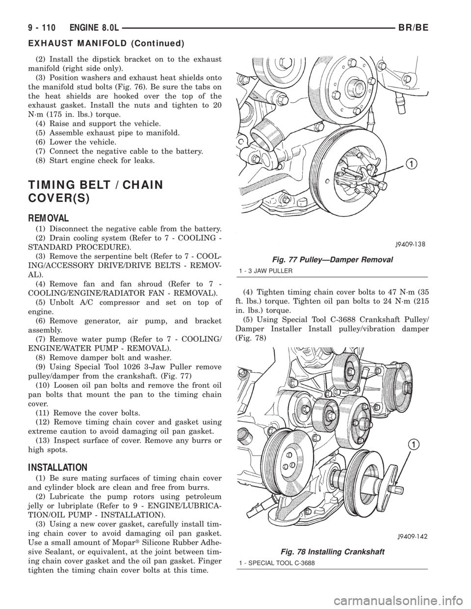
pulley/damper from the crankshaft. (Fig. 77)
(10) Loosen oil pan bolts and remove the front oil
pan bolts that mount the pan to the timing chain
cover.
(11) Remove the cover bolts.
(12) Remove timing chain cover and gasket using
extreme caution to avoid damaging oil pan gasket.
(13) Inspect surface of cover. Remove any burrs or
high spots.
INSTALLATION
(1) Be sure mating surfaces of timing chain cover
and cylinder block are clean and free from burrs.
(2) Lubricate the pump rotors using petroleum
jelly or lubriplate (Refer to 9 - ENGINE/LUBRICA-
TION/OIL PUMP - INSTALLATION).
(3) Using a new cover gasket, carefully install tim-
ing chain cover to avoid damaging oil pan gasket.
Use a small amount of MopartSilicone Rubber Adhe-
sive Sealant, or equivalent, at the joint between tim-
ing chain cover gasket and the oil pan gasket. Finger
tighten the timing chain cover bolts at this time.(4) Tighten timing chain cover bolts to 47 N´m (35
ft. lbs.) torque. Tighten oil pan bolts to 24 N´m (215
in. lbs.) torque.
(5) Using Special Tool C-3688 Crankshaft Pulley/
Damper Installer Install pulley/vibration damper
(Fig. 78)
Fig. 77 PulleyÐDamper Removal
1-3JAWPULLER
Fig. 78 Installing Crankshaft
1 - SPECIAL TOOL C-3688
9 - 110 ENGINE 8.0LBR/BE
EXHAUST MANIFOLD (Continued)
Page 1186 of 2255
(6) Prime oil pump by squirting oil in the oil filter
mounting hole and filling the J-trap of the front tim-
ing cover. When oil is running out, install oil filter
that has been filled with oil.
(7) Install water pump and housing assembly
using new o-ring (Refer to 7 - COOLING/ENGINE/
WATER PUMP - INSTALLATION).
(8) Install generator, air pump, and bracket assem-
bly.
(9) Install A/C compressor (Refer to 24 - HEATING
& AIR CONDITIONING/PLUMBING/A/C COM-
PRESSOR - INSTALLATION).
(10) (10) Install the radiator fan (Refer to 7 -
COOLING/ENGINE/RADIATOR FAN - INSTALLA-
TION).
(11) Position the fan shroud and install the bolts.
Tighten the bolts to 11 N´m (95 in. lbs.) torque.
(12) Install the serpentine belt (Refer to 7 - COOL-
ING/ACCESSORY DRIVE/DRIVE BELTS - INSTAL-
LATION).
(13) Fill cooling system (Refer to 7 - COOLING -
STANDARD PROCEDURE).
(14) Connect the negative cable to the battery.
(15) Road test vehicle and check for leaks.
TIMING BELT/CHAIN AND
SPROCKETS
REMOVAL
(1) Remove timing chain cover and gasket using
extreme caution to avoid damaging oil pan gasket
(Refer to 9 - ENGINE/VALVE TIMING/TIMING
BELT / CHAIN COVER(S) - REMOVAL).
(2) Aline camshaft and crankshaft centerline.
Remove camshaft sprocket attaching bolt and remove
timing chain and camshaft sprockets.
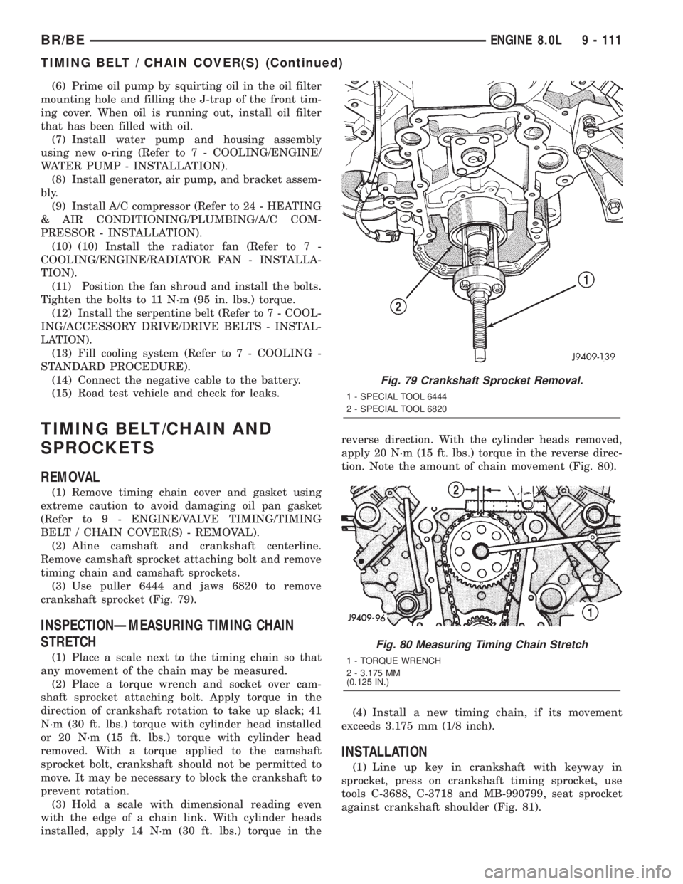
(3) Use puller 6444 and jaws 6820 to remove
crankshaft sprocket (Fig. 79).
INSPECTIONÐMEASURING TIMING CHAIN
STRETCH
(1) Place a scale next to the timing chain so that
any movement of the chain may be measured.
(2) Place a torque wrench and socket over cam-
shaft sprocket attaching bolt. Apply torque in the
direction of crankshaft rotation to take up slack; 41
N´m (30 ft. lbs.) torque with cylinder head installed
or 20 N´m (15 ft. lbs.) torque with cylinder head
removed. With a torque applied to the camshaft
sprocket bolt, crankshaft should not be permitted to
move. It may be necessary to block the crankshaft to
prevent rotation.
(3) Hold a scale with dimensional reading even
with the edge of a chain link. With cylinder heads
installed, apply 14 N´m (30 ft. lbs.) torque in thereverse direction. With the cylinder heads removed,
apply 20 N´m (15 ft. lbs.) torque in the reverse direc-
tion. Note the amount of chain movement (Fig. 80).
(4) Install a new timing chain, if its movement
exceeds 3.175 mm (1/8 inch).
INSTALLATION
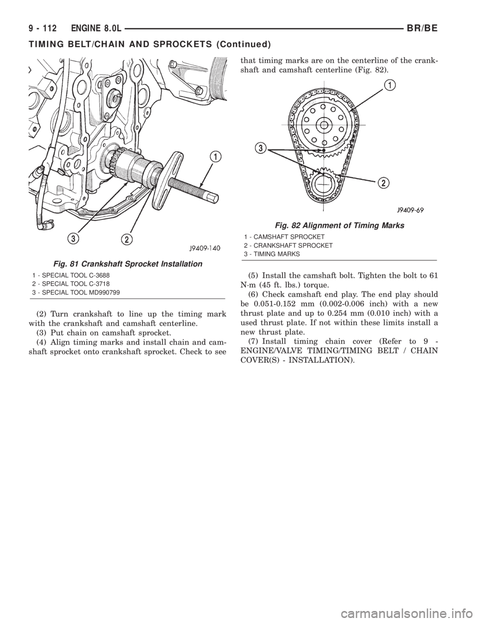
(1) Line up key in crankshaft with keyway in
sprocket, press on crankshaft timing sprocket, use
tools C-3688, C-3718 and MB-990799, seat sprocket
against crankshaft shoulder (Fig. 81).
Fig. 79 Crankshaft Sprocket Removal.
1 - SPECIAL TOOL 6444
2 - SPECIAL TOOL 6820
Fig. 80 Measuring Timing Chain Stretch
1 - TORQUE WRENCH
2 - 3.175 MM
(0.125 IN.)
BR/BEENGINE 8.0L 9 - 111
TIMING BELT / CHAIN COVER(S) (Continued)
Page 1187 of 2255
(2) Turn crankshaft to line up the timing mark
with the crankshaft and camshaft centerline.
(3) Put chain on camshaft sprocket.
(4) Align timing marks and install chain and cam-
shaft sprocket onto crankshaft sprocket. Check to seethat timing marks are on the centerline of the crank-
shaft and camshaft centerline (Fig. 82).
(5) Install the camshaft bolt. Tighten the bolt to 61
N´m (45 ft. lbs.) torque.
(6) Check camshaft end play. The end play should
be 0.051-0.152 mm (0.002-0.006 inch) with a new
thrust plate and up to 0.254 mm (0.010 inch) with a
used thrust plate. If not within these limits install a
new thrust plate.
(7) Install timing chain cover (Refer to 9 -
ENGINE/VALVE TIMING/TIMING BELT / CHAIN
COVER(S) - INSTALLATION).
Fig. 81 Crankshaft Sprocket Installation
1 - SPECIAL TOOL C-3688
2 - SPECIAL TOOL C-3718
3 - SPECIAL TOOL MD990799
Fig. 82 Alignment of Timing Marks
1 - CAMSHAFT SPROCKET
2 - CRANKSHAFT SPROCKET
3 - TIMING MARKS
9 - 112 ENGINE 8.0LBR/BE
TIMING BELT/CHAIN AND SPROCKETS (Continued)
Page 1191 of 2255
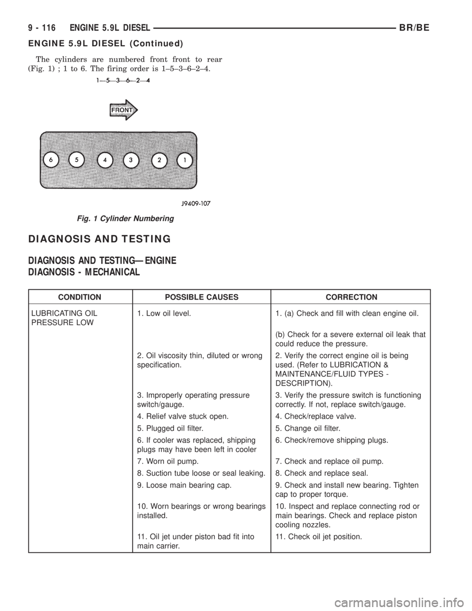
The cylinders are numbered front front to rear
(Fig. 1);1to6.Thefiring order is 1±5±3±6±2±4.
DIAGNOSIS AND TESTING
DIAGNOSIS AND TESTINGÐENGINE
DIAGNOSIS - MECHANICAL
CONDITION POSSIBLE CAUSES CORRECTION
LUBRICATING OIL
PRESSURE LOW1. Low oil level. 1. (a) Check and fill with clean engine oil.
(b) Check for a severe external oil leak that
could reduce the pressure.
2. Oil viscosity thin, diluted or wrong
specification.2. Verify the correct engine oil is being
used. (Refer to LUBRICATION &
MAINTENANCE/FLUID TYPES -
DESCRIPTION).
3. Improperly operating pressure
switch/gauge.3. Verify the pressure switch is functioning
correctly. If not, replace switch/gauge.
4. Relief valve stuck open. 4. Check/replace valve.
5. Plugged oil filter. 5. Change oil filter.
6. If cooler was replaced, shipping
plugs may have been left in cooler6. Check/remove shipping plugs.
7. Worn oil pump. 7. Check and replace oil pump.
8. Suction tube loose or seal leaking. 8. Check and replace seal.
9. Loose main bearing cap. 9. Check and install new bearing. Tighten
cap to proper torque.
10. Worn bearings or wrong bearings
installed.10. Inspect and replace connecting rod or
main bearings. Check and replace piston
cooling nozzles.
11. Oil jet under piston bad fit into
main carrier.11. Check oil jet position.
Fig. 1 Cylinder Numbering
9 - 116 ENGINE 5.9L DIESELBR/BE
ENGINE 5.9L DIESEL (Continued)
Page 1192 of 2255
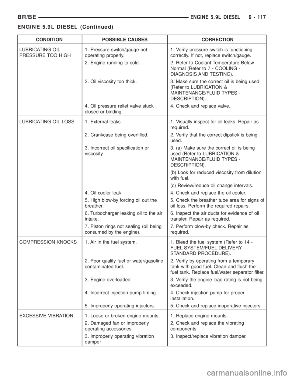
CONDITION POSSIBLE CAUSES CORRECTION
LUBRICATING OIL
PRESSURE TOO HIGH1. Pressure switch/gauge not
operating properly.1. Verify pressure switch is functioning
correctly. If not, replace switch/gauge.
2. Engine running to cold. 2. Refer to Coolant Temperature Below
Normal (Refer to 7 - COOLING -
DIAGNOSIS AND TESTING).
3. Oil viscosity too thick. 3. Make sure the correct oil is being used.
(Refer to LUBRICATION &
MAINTENANCE/FLUID TYPES -
DESCRIPTION).
4. Oil pressure relief valve stuck
closed or binding4. Check and replace valve.
LUBRICATING OIL LOSS 1. External leaks. 1. Visually inspect for oil leaks. Repair as
required.
2. Crankcase being overfilled. 2. Verify that the correct dipstick is being
used.
3. Incorrect oil specification or
viscosity.3. (a) Make sure the correct oil is being
used (Refer to LUBRICATION &
MAINTENANCE/FLUID TYPES -
DESCRIPTION).
(b) Look for reduced viscosity from dilution
with fuel.
(c) Review/reduce oil change intervals.
4. Oil cooler leak 4. Check and replace the oil cooler.
5. High blow-by forcing oil out the
breather.5. Check the breather tube area for signs of
oil loss. Perform the required repairs.
6. Turbocharger leaking oil to the air
intake.6. Inspect the air ducts for evidence of oil
transfer. Repair as required.
7. Piston rings not sealing (oil being
consumed by the engine).7. Perform blow-by check. Repair as
required.
COMPRESSION KNOCKS 1. Air in the fuel system. 1. Bleed the fuel system (Refer to 14 -
FUEL SYSTEM/FUEL DELIVERY -
STANDARD PROCEDURE).
2. Poor quality fuel or water/gasoline
contaminated fuel.2. Verify by operating from a temporary
tank with good fuel. Clean and flush the
fuel tank. Replace fuel/water separator filter.
3. Engine overloaded. 3. Verify the engine load rating is not being
exceeded.
4. Incorrect injection pump timing. 4. Check injection pump for proper
installation.
5. Improperly operating injectors. 5. Check and replace inoperative injectors.
EXCESSIVE VIBRATION 1. Loose or broken engine mounts. 1. Replace engine mounts.
2. Damaged fan or improperly
operating accessories.2. Check and replace the vibrating
components.
3. Improperly operating vibration
damper3. Inspect/replace vibration damper.
BR/BEENGINE 5.9L DIESEL 9 - 117
ENGINE 5.9L DIESEL (Continued)