check engine DODGE RAM 2002 Service Repair Manual
[x] Cancel search | Manufacturer: DODGE, Model Year: 2002, Model line: RAM, Model: DODGE RAM 2002Pages: 2255, PDF Size: 62.07 MB
Page 1113 of 2255
(8) Start and operate engine. Warm up to normal
operating temperature.
CAUTION: To prevent damage to valve mechanism,
engine must not be run above fast idle until all
hydraulic tappets have filled with oil and have
become quiet.
PISTON & CONNECTING ROD
DESCRIPTION
The pistons are made of aluminum and have three
ring grooves, the top two grooves are for the compres-
sion rings and the bottom groove is for the oil control
ring. The connecting rods are forged steel and are
coined prior to heat treat. The piston pins are press
fit.
STANDARD PROCEDURE - PISTON FITTING
Piston and cylinder wall must be clean and dry.
Specified clearance between the piston and the cylin-
der wall is 0.013-0.038 mm (0.0005-0.0015 inch) at
21ÉC (70ÉF).
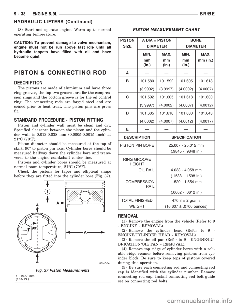
Piston diameter should be measured at the top of
skirt, 90É to piston pin axis. Cylinder bores should be
measured halfway down the cylinder bore and trans-
verse to the engine crankshaft center line.
Pistons and cylinder bores should be measured at
normal room temperature, 21ÉC (70ÉF).
Check the pistons for taper and elliptical shape
before they are fitted into the cylinder bore (Fig. 37).
PISTON MEASUREMENT CHART
PISTON A DIA = PISTON BORE
SIZE DIAMETER DIAMETER
MIN. MAX. MIN. MAX.
mm
(in.)mm
(in.)mm
(in.)mm (in.)
AÐÐÐ Ð
B101.580 101.592 101.605 101.618
(3.9992) (3.9997) (4.0002) (4.0007)
C101.592 101.605 101.618 101.630
(3.9997) (4.0002) (4.0007) (4.0012)
D101.605 101.618 101.630 101.643
(4.0002) (4.0007) (4.0012) (4.0017)
EÐÐÐ Ð
DESCRIPTION SPECIFICATION
PISTON PIN BORE 25.007 - 25.015 mm
(.9845 - .9848 in.)
RING GROOVE
HEIGHT
OIL RAIL 4.033 - 4.058 mm
(.1588 - .1598 in.)
COMPRESSION
RAIL1.529 - 1.554 mm
(.0602 - .0612 in.)
TOTAL FINISHED 470.8 2 grams
WEIGHT (16.607 .0706 ounces)
REMOVAL
(1) Remove the engine from the vehicle (Refer to 9
- ENGINE - REMOVAL).
(2) Remove the cylinder head (Refer to 9 -
ENGINE/CYLINDER HEAD - REMOVAL).
(3) Remove the oil pan (Refer to 9 - ENGINE/LU-
BRICATION/OIL PAN - REMOVAL).
(4) Remove top ridge of cylinder bores with a reli-
able ridge reamer before removing pistons from cyl-
inder block. Be sure to keep tops of pistons covered
during this operation.
(5) Be sure each connecting rod and connecting rod
cap is identified with the cylinder number. Remove
connecting rod cap. Install connecting rod bolt guide
set on connecting rod bolts.
Fig. 37 Piston Measurements
1 - 49.53 mm
(1.95 IN.)
9 - 38 ENGINE 5.9LBR/BE
HYDRAULIC LIFTERS (Continued)
Page 1114 of 2255
(6) Pistons and connecting rods must be removed
from top of cylinder block. When removing the
assemblies from the engine, rotate crankshaft so that
the connecting rod is centered in cylinder bore and at
BDC.Be careful not to nick crankshaft journals.
(7) After removal, install bearing cap on the mat-
ing rod.
CLEANING
Clean the piston and connecting rod assembly
using a suitable solvent.
INSPECTION
Check the connecting rod journal for excessive
wear, taper and scoring (Refer to 9 - ENGINE/EN-
GINE BLOCK/CONNECTING ROD BEARINGS -
STANDARD PROCEDURE).
Check the connecting rod for signs of twist or bend-
ing.
Check the piston for taper and elliptical shape
before it is fitted into the cylinder bore (Refer to 9 -
ENGINE/ENGINE BLOCK/PISTON & CONNECT-
ING ROD - STANDARD PROCEDURE).
Check the piston for scoring, or scraping marks in
the piston skirts. Check the ring lands for cracks
and/or deterioration.
INSTALLATION
(1) Be sure that compression ring gaps are stag-
gered so that neither is in line with oil ring rail gap.
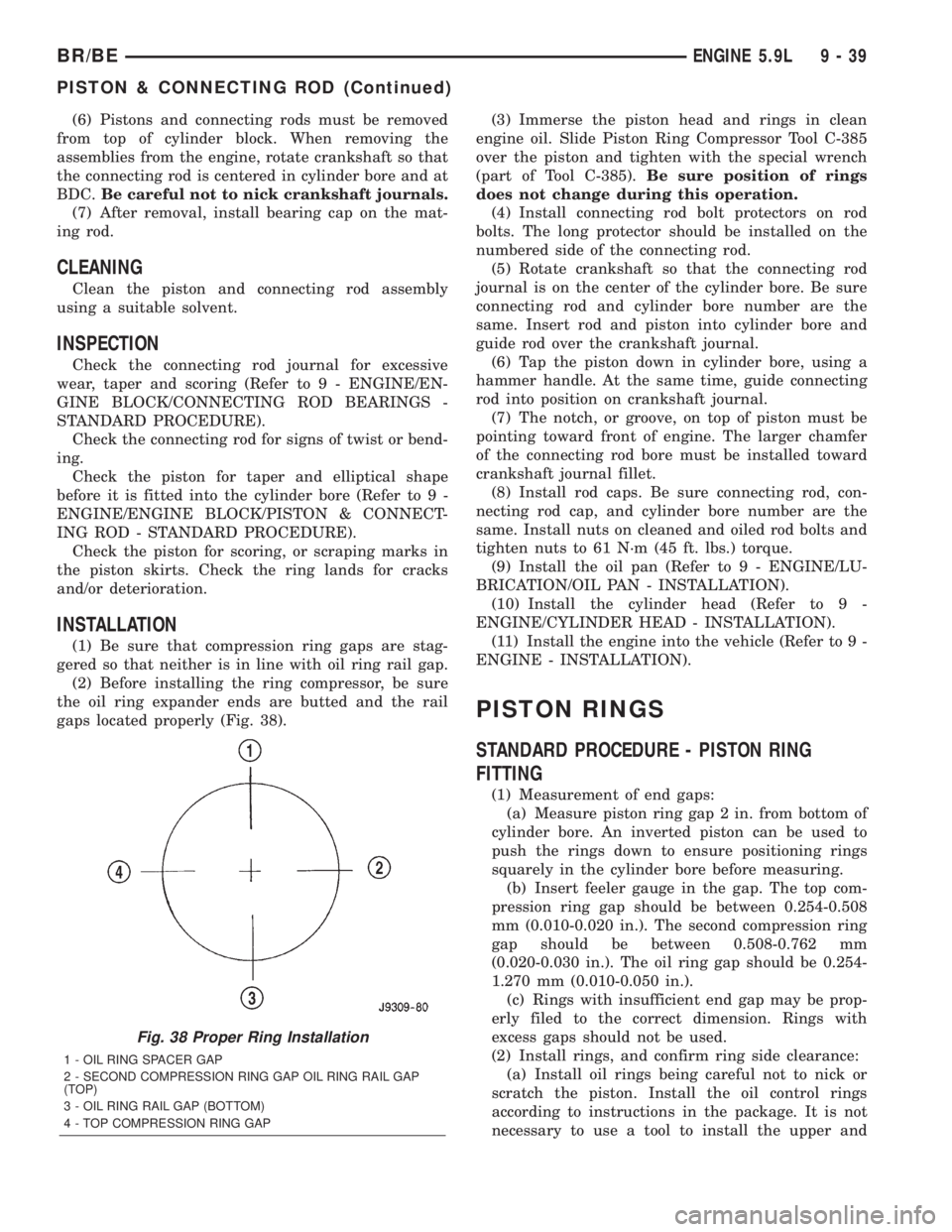
(2) Before installing the ring compressor, be sure
the oil ring expander ends are butted and the rail
gaps located properly (Fig. 38).(3) Immerse the piston head and rings in clean
engine oil. Slide Piston Ring Compressor Tool C-385
over the piston and tighten with the special wrench
(part of Tool C-385).Be sure position of rings
does not change during this operation.
(4) Install connecting rod bolt protectors on rod
bolts. The long protector should be installed on the
numbered side of the connecting rod.
(5) Rotate crankshaft so that the connecting rod
journal is on the center of the cylinder bore. Be sure
connecting rod and cylinder bore number are the
same. Insert rod and piston into cylinder bore and
guide rod over the crankshaft journal.
(6) Tap the piston down in cylinder bore, using a
hammer handle. At the same time, guide connecting
rod into position on crankshaft journal.
(7) The notch, or groove, on top of piston must be
pointing toward front of engine. The larger chamfer
of the connecting rod bore must be installed toward
crankshaft journal fillet.
(8) Install rod caps. Be sure connecting rod, con-
necting rod cap, and cylinder bore number are the
same. Install nuts on cleaned and oiled rod bolts and
tighten nuts to 61 N´m (45 ft. lbs.) torque.
(9) Install the oil pan (Refer to 9 - ENGINE/LU-
BRICATION/OIL PAN - INSTALLATION).
(10) Install the cylinder head (Refer to 9 -
ENGINE/CYLINDER HEAD - INSTALLATION).
(11) Install the engine into the vehicle (Refer to 9 -
ENGINE - INSTALLATION).
PISTON RINGS
STANDARD PROCEDURE - PISTON RING
FITTING
(1) Measurement of end gaps:
(a) Measure piston ring gap 2 in. from bottom of
cylinder bore. An inverted piston can be used to
push the rings down to ensure positioning rings
squarely in the cylinder bore before measuring.
(b) Insert feeler gauge in the gap. The top com-
pression ring gap should be between 0.254-0.508
mm (0.010-0.020 in.). The second compression ring
gap should be between 0.508-0.762 mm
(0.020-0.030 in.). The oil ring gap should be 0.254-
1.270 mm (0.010-0.050 in.).
(c) Rings with insufficient end gap may be prop-
erly filed to the correct dimension. Rings with
excess gaps should not be used.
(2) Install rings, and confirm ring side clearance:
(a) Install oil rings being careful not to nick or
scratch the piston. Install the oil control rings
according to instructions in the package. It is not
necessary to use a tool to install the upper and
Fig. 38 Proper Ring Installation
1 - OIL RING SPACER GAP
2 - SECOND COMPRESSION RING GAP OIL RING RAIL GAP
(TOP)
3 - OIL RING RAIL GAP (BOTTOM)
4 - TOP COMPRESSION RING GAP
BR/BEENGINE 5.9L 9 - 39
PISTON & CONNECTING ROD (Continued)
Page 1118 of 2255
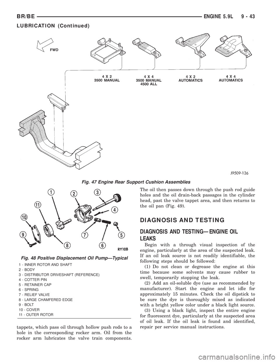
tappets, which pass oil through hollow push rods to a
hole in the corresponding rocker arm. Oil from the
rocker arm lubricates the valve train components.The oil then passes down through the push rod guide
holes and the oil drain-back passages in the cylinder
head, past the valve tappet area, and then returns to
the oil pan (Fig. 49).
DIAGNOSIS AND TESTING
DIAGNOSIS AND TESTINGÐENGINE OIL
LEAKS
Begin with a through visual inspection of the
engine, particularly at the area of the suspected leak.
If an oil leak source is not readily identifiable, the
following steps should be followed:
(1) Do not clean or degrease the engine at this
time because some solvents may cause rubber to
swell, temporarily stopping the leak.
(2) Add an oil-soluble dye (use as recommended by
manufacturer). Start the engine and let idle for
approximately 15 minutes. Check the oil dipstick to
be sure the dye is thoroughly mixed as indicated
with a bright yellow color under a black light source.
(3) Using a black light, inspect the entire engine
for fluorescent dye, particularly at the suspected area
of oil leak. If the oil leak is found and identified,
repair per service manual instructions.
Fig. 47 Engine Rear Support Cushion Assemblies
Fig. 48 Positive Displacement Oil PumpÐTypical
1 - INNER ROTOR AND SHAFT
2 - BODY
3 - DISTRIBUTOR DRIVESHAFT (REFERENCE)
4 - COTTER PIN
5 - RETAINER CAP
6 - SPRING
7 - RELIEF VALVE
8 - LARGE CHAMFERED EDGE
9 - BOLT
10 - COVER
11 - OUTER ROTOR
BR/BEENGINE 5.9L 9 - 43
LUBRICATION (Continued)
Page 1123 of 2255
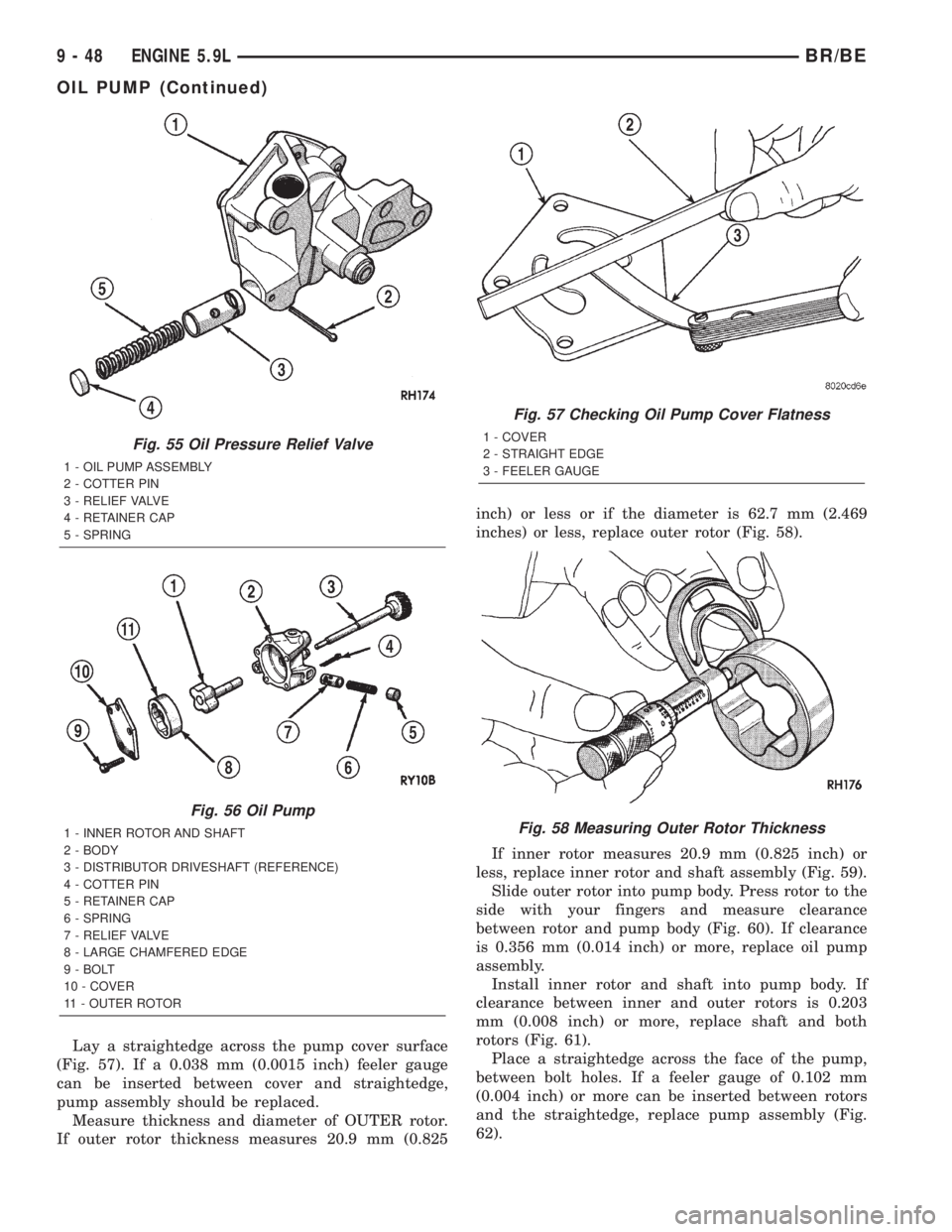
Lay a straightedge across the pump cover surface
(Fig. 57). If a 0.038 mm (0.0015 inch) feeler gauge
can be inserted between cover and straightedge,
pump assembly should be replaced.
Measure thickness and diameter of OUTER rotor.
If outer rotor thickness measures 20.9 mm (0.825inch) or less or if the diameter is 62.7 mm (2.469
inches) or less, replace outer rotor (Fig. 58).
If inner rotor measures 20.9 mm (0.825 inch) or
less, replace inner rotor and shaft assembly (Fig. 59).
Slide outer rotor into pump body. Press rotor to the
side with your fingers and measure clearance
between rotor and pump body (Fig. 60). If clearance
is 0.356 mm (0.014 inch) or more, replace oil pump
assembly.
Install inner rotor and shaft into pump body. If
clearance between inner and outer rotors is 0.203
mm (0.008 inch) or more, replace shaft and both
rotors (Fig. 61).
Place a straightedge across the face of the pump,
between bolt holes. If a feeler gauge of 0.102 mm
(0.004 inch) or more can be inserted between rotors
and the straightedge, replace pump assembly (Fig.
62).
Fig. 55 Oil Pressure Relief Valve
1 - OIL PUMP ASSEMBLY
2 - COTTER PIN
3 - RELIEF VALVE
4 - RETAINER CAP
5 - SPRING
Fig. 56 Oil Pump
1 - INNER ROTOR AND SHAFT
2 - BODY
3 - DISTRIBUTOR DRIVESHAFT (REFERENCE)
4 - COTTER PIN
5 - RETAINER CAP
6 - SPRING
7 - RELIEF VALVE
8 - LARGE CHAMFERED EDGE
9 - BOLT
10 - COVER
11 - OUTER ROTOR
Fig. 57 Checking Oil Pump Cover Flatness
1 - COVER
2 - STRAIGHT EDGE
3 - FEELER GAUGE
Fig. 58 Measuring Outer Rotor Thickness
9 - 48 ENGINE 5.9LBR/BE
OIL PUMP (Continued)
Page 1126 of 2255
(13) Disconnect the heater hoses and bypass hose.
(14) Remove the closed crankcase ventilation and
evaporation control systems.
(15) Remove intake manifold bolts.
(16) Lift the intake manifold and throttle body out
of the engine compartment as an assembly.
(17) Remove and discard the flange side gaskets
and the front and rear end seals.
(18) Remove the throttle body bolts and lift the
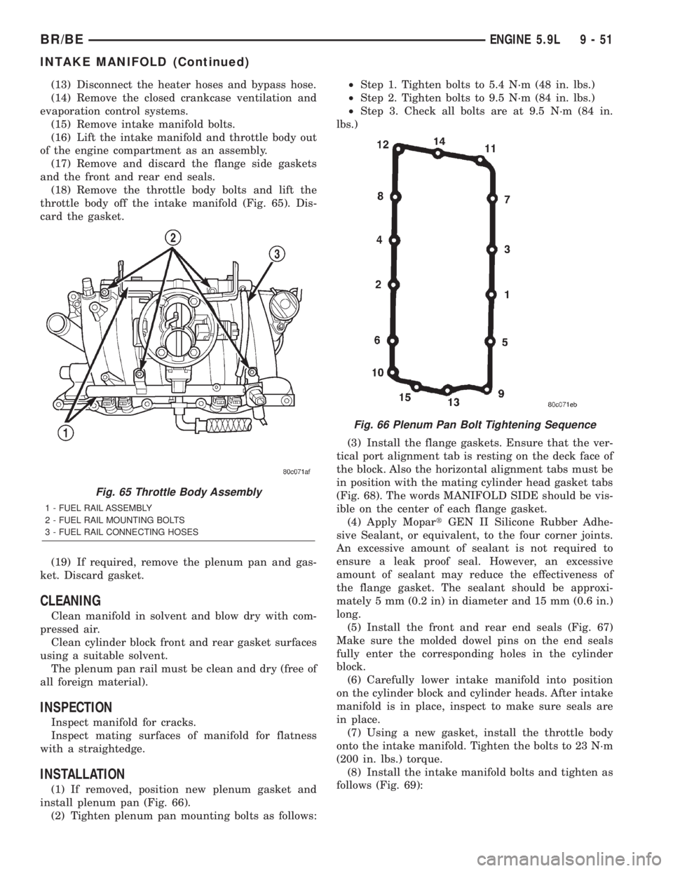
throttle body off the intake manifold (Fig. 65). Dis-
card the gasket.
(19) If required, remove the plenum pan and gas-
ket. Discard gasket.
CLEANING
Clean manifold in solvent and blow dry with com-
pressed air.
Clean cylinder block front and rear gasket surfaces
using a suitable solvent.
The plenum pan rail must be clean and dry (free of
all foreign material).
INSPECTION
Inspect manifold for cracks.
Inspect mating surfaces of manifold for flatness
with a straightedge.
INSTALLATION
(1) If removed, position new plenum gasket and
install plenum pan (Fig. 66).
(2) Tighten plenum pan mounting bolts as follows:²Step 1. Tighten bolts to 5.4 N´m (48 in. lbs.)
²Step 2. Tighten bolts to 9.5 N´m (84 in. lbs.)
²Step 3. Check all bolts are at 9.5 N´m (84 in.
lbs.)
(3) Install the flange gaskets. Ensure that the ver-
tical port alignment tab is resting on the deck face of
the block. Also the horizontal alignment tabs must be
in position with the mating cylinder head gasket tabs
(Fig. 68). The words MANIFOLD SIDE should be vis-
ible on the center of each flange gasket.
(4) Apply MopartGEN II Silicone Rubber Adhe-
sive Sealant, or equivalent, to the four corner joints.
An excessive amount of sealant is not required to
ensure a leak proof seal. However, an excessive
amount of sealant may reduce the effectiveness of
the flange gasket. The sealant should be approxi-
mately 5 mm (0.2 in) in diameter and 15 mm (0.6 in.)
long.
(5) Install the front and rear end seals (Fig. 67)
Make sure the molded dowel pins on the end seals
fully enter the corresponding holes in the cylinder
block.
(6) Carefully lower intake manifold into position
on the cylinder block and cylinder heads. After intake
manifold is in place, inspect to make sure seals are
in place.
(7) Using a new gasket, install the throttle body
onto the intake manifold. Tighten the bolts to 23 N´m
(200 in. lbs.) torque.
(8) Install the intake manifold bolts and tighten as
follows (Fig. 69):
Fig. 65 Throttle Body Assembly
1 - FUEL RAIL ASSEMBLY
2 - FUEL RAIL MOUNTING BOLTS
3 - FUEL RAIL CONNECTING HOSES
Fig. 66 Plenum Pan Bolt Tightening Sequence
BR/BEENGINE 5.9L 9 - 51
INTAKE MANIFOLD (Continued)
Page 1127 of 2255
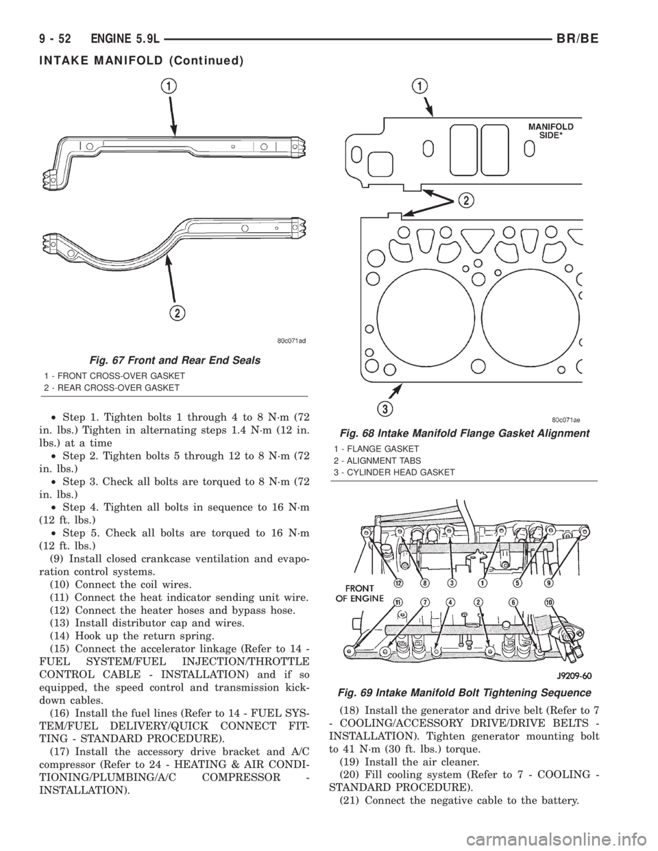
²Step 1. Tighten bolts 1 through 4 to 8 N´m (72
in. lbs.) Tighten in alternating steps 1.4 N´m (12 in.
lbs.) at a time
²Step 2. Tighten bolts 5 through 12 to 8 N´m (72
in. lbs.)
²Step 3. Check all bolts are torqued to 8 N´m (72
in. lbs.)
²Step 4. Tighten all bolts in sequence to 16 N´m
(12 ft. lbs.)
²Step 5. Check all bolts are torqued to 16 N´m
(12 ft. lbs.)
(9) Install closed crankcase ventilation and evapo-
ration control systems.
(10) Connect the coil wires.
(11) Connect the heat indicator sending unit wire.
(12) Connect the heater hoses and bypass hose.
(13) Install distributor cap and wires.
(14) Hook up the return spring.
(15) Connect the accelerator linkage (Refer to 14 -
FUEL SYSTEM/FUEL INJECTION/THROTTLE
CONTROL CABLE - INSTALLATION) and if so
equipped, the speed control and transmission kick-
down cables.
(16) Install the fuel lines (Refer to 14 - FUEL SYS-
TEM/FUEL DELIVERY/QUICK CONNECT FIT-
TING - STANDARD PROCEDURE).
(17) Install the accessory drive bracket and A/C
compressor (Refer to 24 - HEATING & AIR CONDI-
TIONING/PLUMBING/A/C COMPRESSOR -
INSTALLATION).(18) Install the generator and drive belt (Refer to 7
- COOLING/ACCESSORY DRIVE/DRIVE BELTS -
INSTALLATION). Tighten generator mounting bolt
to 41 N´m (30 ft. lbs.) torque.
(19) Install the air cleaner.
(20) Fill cooling system (Refer to 7 - COOLING -
STANDARD PROCEDURE).
(21) Connect the negative cable to the battery.
Fig. 67 Front and Rear End Seals
1 - FRONT CROSS-OVER GASKET
2 - REAR CROSS-OVER GASKET
Fig. 68 Intake Manifold Flange Gasket Alignment
1 - FLANGE GASKET
2 - ALIGNMENT TABS
3 - CYLINDER HEAD GASKET
Fig. 69 Intake Manifold Bolt Tightening Sequence
9 - 52 ENGINE 5.9LBR/BE
INTAKE MANIFOLD (Continued)
Page 1129 of 2255
(3) Remove power steering pump (Refer to 19 -
STEERING/PUMP - REMOVAL).
(4) Remove vibration damper (Refer to 9 -
ENGINE/ENGINE BLOCK/VIBRATION DAMPER -
REMOVAL).
(5) Loosen oil pan bolts and remove the front bolt
at each side.
(6) Remove the cover bolts.
(7) Remove chain case cover and gasket using
extreme caution to avoid damaging oil pan gasket.
INSTALLATION
(1) Be sure mating surfaces of chain case cover
and cylinder block are clean and free from burrs.
(2) The water pump mounting surface must be
cleaned.
(3) Using a new cover gasket, carefully install
chain case cover to avoid damaging oil pan gasket.
Use a small amount of MopartSilicone Rubber Adhe-
sive Sealant, or equivalent, at the joint between tim-
ing chain cover gasket and the oil pan gasket. Finger
tighten the timing chain cover bolts at this time.
NOTE: Special Tool 6635 must be used to align the
front cover and seal with the crankshaft.
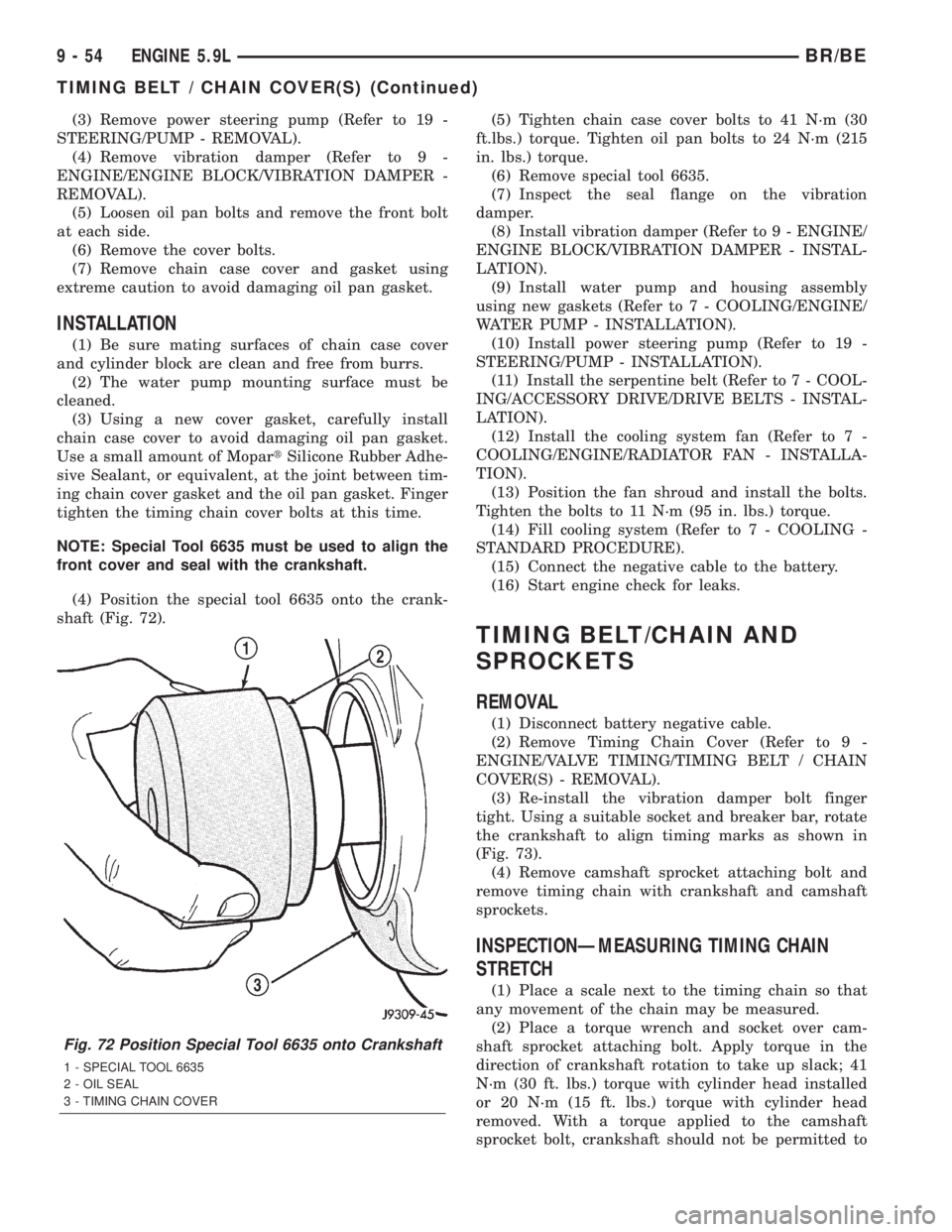
(4) Position the special tool 6635 onto the crank-
shaft (Fig. 72).(5) Tighten chain case cover bolts to 41 N´m (30
ft.lbs.) torque. Tighten oil pan bolts to 24 N´m (215
in. lbs.) torque.
(6) Remove special tool 6635.
(7) Inspect the seal flange on the vibration
damper.
(8) Install vibration damper (Refer to 9 - ENGINE/
ENGINE BLOCK/VIBRATION DAMPER - INSTAL-
LATION).
(9) Install water pump and housing assembly
using new gaskets (Refer to 7 - COOLING/ENGINE/
WATER PUMP - INSTALLATION).
(10) Install power steering pump (Refer to 19 -
STEERING/PUMP - INSTALLATION).
(11) Install the serpentine belt (Refer to 7 - COOL-
ING/ACCESSORY DRIVE/DRIVE BELTS - INSTAL-
LATION).
(12) Install the cooling system fan (Refer to 7 -
COOLING/ENGINE/RADIATOR FAN - INSTALLA-
TION).
(13) Position the fan shroud and install the bolts.
Tighten the bolts to 11 N´m (95 in. lbs.) torque.
(14) Fill cooling system (Refer to 7 - COOLING -
STANDARD PROCEDURE).
(15) Connect the negative cable to the battery.
(16) Start engine check for leaks.
TIMING BELT/CHAIN AND
SPROCKETS
REMOVAL
(1) Disconnect battery negative cable.
(2) Remove Timing Chain Cover (Refer to 9 -
ENGINE/VALVE TIMING/TIMING BELT / CHAIN
COVER(S) - REMOVAL).
(3) Re-install the vibration damper bolt finger
tight. Using a suitable socket and breaker bar, rotate
the crankshaft to align timing marks as shown in
(Fig. 73).
(4) Remove camshaft sprocket attaching bolt and
remove timing chain with crankshaft and camshaft
sprockets.
INSPECTIONÐMEASURING TIMING CHAIN
STRETCH
(1) Place a scale next to the timing chain so that
any movement of the chain may be measured.
(2) Place a torque wrench and socket over cam-
shaft sprocket attaching bolt. Apply torque in the
direction of crankshaft rotation to take up slack; 41
N´m (30 ft. lbs.) torque with cylinder head installed
or 20 N´m (15 ft. lbs.) torque with cylinder head
removed. With a torque applied to the camshaft
sprocket bolt, crankshaft should not be permitted to
Fig. 72 Position Special Tool 6635 onto Crankshaft
1 - SPECIAL TOOL 6635
2 - OIL SEAL
3 - TIMING CHAIN COVER
9 - 54 ENGINE 5.9LBR/BE
TIMING BELT / CHAIN COVER(S) (Continued)
Page 1130 of 2255
move. It may be necessary to block the crankshaft to
prevent rotation.
(3) Hold a scale with dimensional reading even
with the edge of a chain link. With cylinder heads
installed, apply 14 N´m (30 ft. lbs.) torque in the
reverse direction. With the cylinder heads removed,
apply 20 N´m (15 ft. lbs.) torque in the reverse direc-
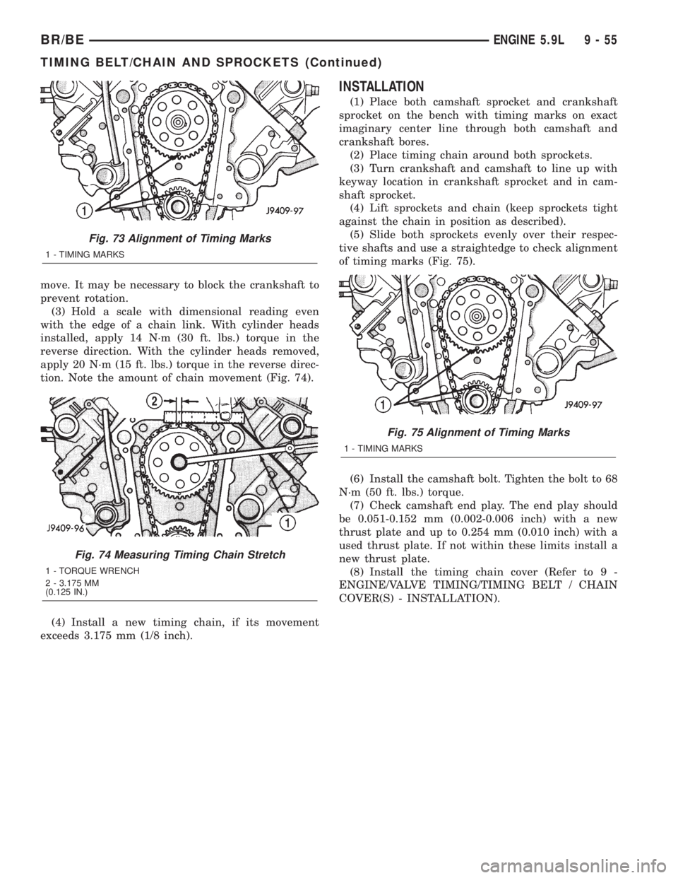
tion. Note the amount of chain movement (Fig. 74).
(4) Install a new timing chain, if its movement
exceeds 3.175 mm (1/8 inch).
INSTALLATION
(1) Place both camshaft sprocket and crankshaft
sprocket on the bench with timing marks on exact
imaginary center line through both camshaft and
crankshaft bores.
(2) Place timing chain around both sprockets.
(3) Turn crankshaft and camshaft to line up with
keyway location in crankshaft sprocket and in cam-
shaft sprocket.
(4) Lift sprockets and chain (keep sprockets tight
against the chain in position as described).
(5) Slide both sprockets evenly over their respec-
tive shafts and use a straightedge to check alignment
of timing marks (Fig. 75).
(6) Install the camshaft bolt. Tighten the bolt to 68
N´m (50 ft. lbs.) torque.
(7) Check camshaft end play. The end play should
be 0.051-0.152 mm (0.002-0.006 inch) with a new
thrust plate and up to 0.254 mm (0.010 inch) with a
used thrust plate. If not within these limits install a
new thrust plate.
(8) Install the timing chain cover (Refer to 9 -
ENGINE/VALVE TIMING/TIMING BELT / CHAIN
COVER(S) - INSTALLATION).
Fig. 73 Alignment of Timing Marks
1 - TIMING MARKS
Fig. 74 Measuring Timing Chain Stretch
1 - TORQUE WRENCH
2 - 3.175 MM
(0.125 IN.)
Fig. 75 Alignment of Timing Marks
1 - TIMING MARKS
BR/BEENGINE 5.9L 9 - 55
TIMING BELT/CHAIN AND SPROCKETS (Continued)
Page 1134 of 2255
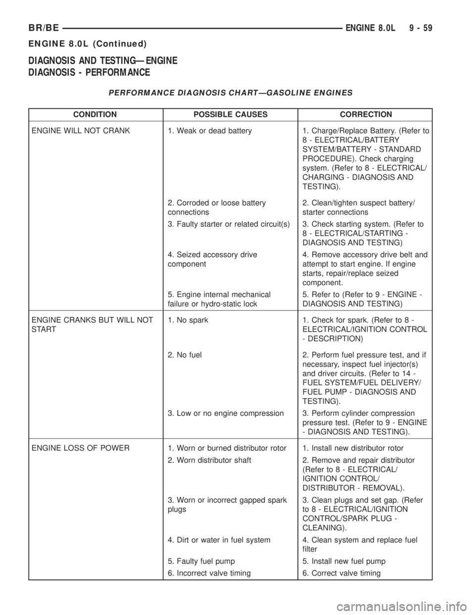
DIAGNOSIS AND TESTINGÐENGINE
DIAGNOSIS - PERFORMANCE
PERFORMANCE DIAGNOSIS CHARTÐGASOLINE ENGINES
CONDITION POSSIBLE CAUSES CORRECTION
ENGINE WILL NOT CRANK 1. Weak or dead battery 1. Charge/Replace Battery. (Refer to
8 - ELECTRICAL/BATTERY
SYSTEM/BATTERY - STANDARD
PROCEDURE). Check charging
system. (Refer to 8 - ELECTRICAL/
CHARGING - DIAGNOSIS AND
TESTING).
2. Corroded or loose battery
connections2. Clean/tighten suspect battery/
starter connections
3. Faulty starter or related circuit(s) 3. Check starting system. (Refer to
8 - ELECTRICAL/STARTING -
DIAGNOSIS AND TESTING)
4. Seized accessory drive
component4. Remove accessory drive belt and
attempt to start engine. If engine
starts, repair/replace seized
component.
5. Engine internal mechanical
failure or hydro-static lock5. Refer to (Refer to 9 - ENGINE -
DIAGNOSIS AND TESTING)
ENGINE CRANKS BUT WILL NOT
START1. No spark 1. Check for spark. (Refer to 8 -
ELECTRICAL/IGNITION CONTROL
- DESCRIPTION)
2. No fuel 2. Perform fuel pressure test, and if
necessary, inspect fuel injector(s)
and driver circuits. (Refer to 14 -
FUEL SYSTEM/FUEL DELIVERY/
FUEL PUMP - DIAGNOSIS AND
TESTING).
3. Low or no engine compression 3. Perform cylinder compression
pressure test. (Refer to 9 - ENGINE
- DIAGNOSIS AND TESTING).
ENGINE LOSS OF POWER 1. Worn or burned distributor rotor 1. Install new distributor rotor
2. Worn distributor shaft 2. Remove and repair distributor
(Refer to 8 - ELECTRICAL/
IGNITION CONTROL/
DISTRIBUTOR - REMOVAL).
3. Worn or incorrect gapped spark
plugs3. Clean plugs and set gap. (Refer
to 8 - ELECTRICAL/IGNITION
CONTROL/SPARK PLUG -
CLEANING).
4. Dirt or water in fuel system 4. Clean system and replace fuel
filter
5. Faulty fuel pump 5. Install new fuel pump
6. Incorrect valve timing 6. Correct valve timing
BR/BEENGINE 8.0L 9 - 59
ENGINE 8.0L (Continued)
Page 1135 of 2255
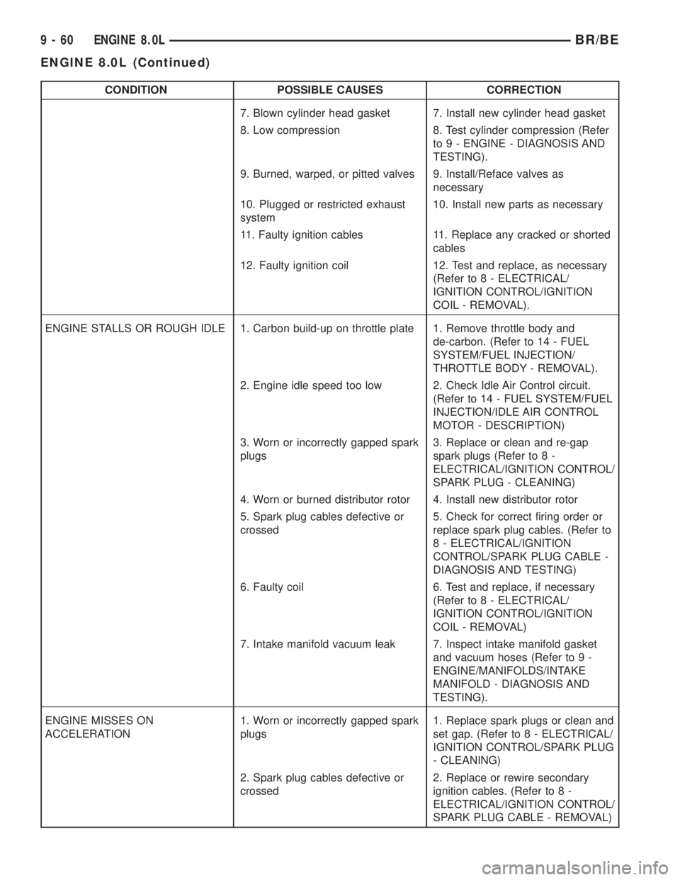
CONDITION POSSIBLE CAUSES CORRECTION
7. Blown cylinder head gasket 7. Install new cylinder head gasket
8. Low compression 8. Test cylinder compression (Refer
to 9 - ENGINE - DIAGNOSIS AND
TESTING).
9. Burned, warped, or pitted valves 9. Install/Reface valves as
necessary
10. Plugged or restricted exhaust
system10. Install new parts as necessary
11. Faulty ignition cables 11. Replace any cracked or shorted
cables
12. Faulty ignition coil 12. Test and replace, as necessary
(Refer to 8 - ELECTRICAL/
IGNITION CONTROL/IGNITION
COIL - REMOVAL).
ENGINE STALLS OR ROUGH IDLE 1. Carbon build-up on throttle plate 1. Remove throttle body and
de-carbon. (Refer to 14 - FUEL
SYSTEM/FUEL INJECTION/
THROTTLE BODY - REMOVAL).
2. Engine idle speed too low 2. Check Idle Air Control circuit.
(Refer to 14 - FUEL SYSTEM/FUEL
INJECTION/IDLE AIR CONTROL
MOTOR - DESCRIPTION)
3. Worn or incorrectly gapped spark
plugs3. Replace or clean and re-gap
spark plugs (Refer to 8 -
ELECTRICAL/IGNITION CONTROL/
SPARK PLUG - CLEANING)
4. Worn or burned distributor rotor 4. Install new distributor rotor
5. Spark plug cables defective or
crossed5. Check for correct firing order or
replace spark plug cables. (Refer to
8 - ELECTRICAL/IGNITION
CONTROL/SPARK PLUG CABLE -
DIAGNOSIS AND TESTING)
6. Faulty coil 6. Test and replace, if necessary
(Refer to 8 - ELECTRICAL/
IGNITION CONTROL/IGNITION
COIL - REMOVAL)
7. Intake manifold vacuum leak 7. Inspect intake manifold gasket
and vacuum hoses (Refer to 9 -
ENGINE/MANIFOLDS/INTAKE
MANIFOLD - DIAGNOSIS AND
TESTING).
ENGINE MISSES ON
ACCELERATION1. Worn or incorrectly gapped spark
plugs1. Replace spark plugs or clean and
set gap. (Refer to 8 - ELECTRICAL/
IGNITION CONTROL/SPARK PLUG
- CLEANING)
2. Spark plug cables defective or
crossed2. Replace or rewire secondary
ignition cables. (Refer to 8 -
ELECTRICAL/IGNITION CONTROL/
SPARK PLUG CABLE - REMOVAL)
9 - 60 ENGINE 8.0LBR/BE
ENGINE 8.0L (Continued)