PCM DODGE RAM 2002 Service Owner's Manual
[x] Cancel search | Manufacturer: DODGE, Model Year: 2002, Model line: RAM, Model: DODGE RAM 2002Pages: 2255, PDF Size: 62.07 MB
Page 403 of 2255
Excessive IOD can be caused by:
²Electrical items left on.
²Faulty or improperly adjusted switches.
²Faulty or shorted electronic modules and compo-
nents.
²An internally shorted generator.
²Intermittent shorts in the wiring.
If the IOD is over thirty-five milliamperes, the
problem must be found and corrected before replac-
ing a battery. In most cases, the battery can becharged and returned to service after the excessive
IOD condition has been corrected.
(1) Verify that all electrical accessories are off.
Turn off all lamps, remove the ignition key, and close
all doors. If the vehicle is equipped with an illumi-
nated entry system or an electronically tuned radio,
allow the electronic timer function of these systems
to automatically shut off (time out). This may take
up to three minutes. See the Electronic Module Igni-
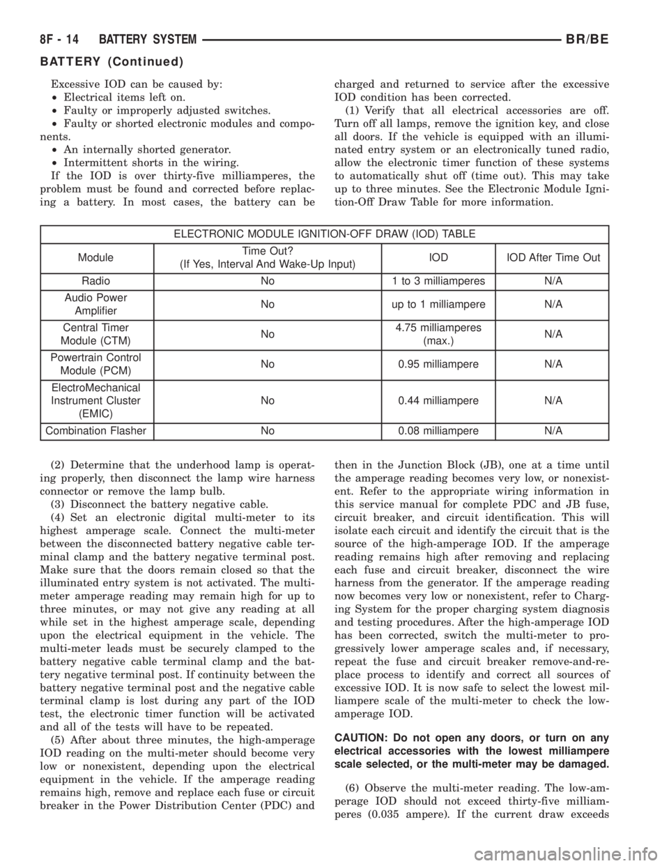
tion-Off Draw Table for more information.
ELECTRONIC MODULE IGNITION-OFF DRAW (IOD) TABLE
ModuleTime Out?
(If Yes, Interval And Wake-Up Input)IOD IOD After Time Out
Radio No 1 to 3 milliamperes N/A
Audio Power
AmplifierNo up to 1 milliampere N/A
Central Timer
Module (CTM)No4.75 milliamperes
(max.)N/A
Powertrain Control
Module (PCM)No 0.95 milliampere N/A
ElectroMechanical
Instrument Cluster
(EMIC)No 0.44 milliampere N/A
Combination Flasher No 0.08 milliampere N/A
(2) Determine that the underhood lamp is operat-
ing properly, then disconnect the lamp wire harness
connector or remove the lamp bulb.
(3) Disconnect the battery negative cable.
(4) Set an electronic digital multi-meter to its
highest amperage scale. Connect the multi-meter
between the disconnected battery negative cable ter-
minal clamp and the battery negative terminal post.
Make sure that the doors remain closed so that the
illuminated entry system is not activated. The multi-
meter amperage reading may remain high for up to
three minutes, or may not give any reading at all
while set in the highest amperage scale, depending
upon the electrical equipment in the vehicle. The
multi-meter leads must be securely clamped to the
battery negative cable terminal clamp and the bat-
tery negative terminal post. If continuity between the
battery negative terminal post and the negative cable
terminal clamp is lost during any part of the IOD
test, the electronic timer function will be activated
and all of the tests will have to be repeated.
(5) After about three minutes, the high-amperage
IOD reading on the multi-meter should become very
low or nonexistent, depending upon the electrical
equipment in the vehicle. If the amperage reading
remains high, remove and replace each fuse or circuit
breaker in the Power Distribution Center (PDC) andthen in the Junction Block (JB), one at a time until
the amperage reading becomes very low, or nonexist-
ent. Refer to the appropriate wiring information in
this service manual for complete PDC and JB fuse,
circuit breaker, and circuit identification. This will
isolate each circuit and identify the circuit that is the
source of the high-amperage IOD. If the amperage
reading remains high after removing and replacing
each fuse and circuit breaker, disconnect the wire
harness from the generator. If the amperage reading
now becomes very low or nonexistent, refer to Charg-
ing System for the proper charging system diagnosis
and testing procedures. After the high-amperage IOD
has been corrected, switch the multi-meter to pro-
gressively lower amperage scales and, if necessary,
repeat the fuse and circuit breaker remove-and-re-
place process to identify and correct all sources of
excessive IOD. It is now safe to select the lowest mil-
liampere scale of the multi-meter to check the low-
amperage IOD.
CAUTION: Do not open any doors, or turn on any
electrical accessories with the lowest milliampere
scale selected, or the multi-meter may be damaged.
(6) Observe the multi-meter reading. The low-am-
perage IOD should not exceed thirty-five milliam-
peres (0.035 ampere). If the current draw exceeds
8F - 14 BATTERY SYSTEMBR/BE
BATTERY (Continued)
Page 414 of 2255
CHARGING
TABLE OF CONTENTS
page page
CHARGING
DESCRIPTION.........................25
OPERATION...........................25
DIAGNOSIS AND TESTING - CHARGING
SYSTEM............................25
SPECIFICATIONS
GENERATOR RATINGS.................26
SPECIFICATIONS - TORQUE -
GENERATOR/CHARGING SYSTEM........27
BATTERY TEMPERATURE SENSOR
DESCRIPTION.........................27OPERATION...........................27
REMOVAL.............................27
INSTALLATION.........................28
GENERATOR
DESCRIPTION.........................28
OPERATION...........................28
REMOVAL.............................28
INSTALLATION.........................30
VOLTAGE REGULATOR
DESCRIPTION.........................30
OPERATION...........................30
CHARGING
DESCRIPTION
The charging system consists of:
²Generator
²Electronic Voltage Regulator (EVR) circuitry
within the Powertrain Control Module (PCM)
²Ignition switch
²Battery (refer to 8, Battery for information)
²Battery temperature sensor
²Check Gauges Lamp (if equipped)
²Voltmeter (refer to 8, Instrument Panel and
Gauges for information)
²Wiring harness and connections (refer to 8, Wir-
ing Diagrams for information)
OPERATION
The charging system is turned on and off with the
ignition switch. The system is on when the engine is
running and the ASD relay is energized. When the
ASD relay is on, voltage is supplied to the ASD relay
sense circuit at the PCM. This voltage is connected
through the PCM and supplied to one of the genera-
tor field terminals (Gen. Source +) at the back of the
generator.
The amount of direct current produced by the gen-
erator is controlled by the EVR (field control) cir-
cuitry contained within the PCM. This circuitry is
connected in series with the second rotor field termi-
nal and ground.
A battery temperature sensor, located in the bat-
tery tray housing, is used to sense battery tempera-
ture. This temperature data, along with data from
monitored line voltage, is used by the PCM to vary
the battery charging rate. This is done by cycling theground path to control the strength of the rotor mag-
netic field. The PCM then compensates and regulates
generator current output accordingly.
All vehicles are equipped with On-Board Diagnos-
tics (OBD). All OBD-sensed systems, including EVR
(field control) circuitry, are monitored by the PCM.
Each monitored circuit is assigned a Diagnostic Trou-
ble Code (DTC). The PCM will store a DTC in elec-
tronic memory for certain failures it detects. Refer to
On-Board Diagnostics in 25, Emission Control Sys-
tem for more DTC information and a list of codes.
The Check Gauges Lamp (if equipped) monitors:
charging system voltage,engine coolant tempera-
ture and engine oil pressure. If an extreme condition
is indicated, the lamp will be illuminated. This is
done as reminder to check the three gauges. The sig-
nal to activate the lamp is sent via the CCD bus cir-
cuits. The lamp is located on the instrument panel.
Refer to 8, Instrument Panel and Gauges for addi-
tional information.
DIAGNOSIS AND TESTING - CHARGING
SYSTEM
The following procedures may be used to diagnose
the charging system if:
²the check gauges lamp (if equipped) is illumi-
nated with the engine running
²the voltmeter (if equipped) does not register
properly
²an undercharged or overcharged battery condi-
tion occurs.
Remember that an undercharged battery is often
caused by:
²accessories being left on with the engine not
running
BR/BECHARGING 8F - 25
Page 415 of 2255
²a faulty or improperly adjusted switch that
allows a lamp to stay on. Refer to Ignition-Off Draw
Test in 8, Battery for more information.
INSPECTION
The Powertrain Control Module (PCM) monitors
critical input and output circuits of the charging sys-
tem, making sure they are operational. A Diagnostic
Trouble Code (DTC) is assigned to each input and
output circuit monitored by the On-Board Diagnostic
(OBD) system. Some charging system circuits are
checked continuously, and some are checked only
under certain conditions.
Refer to Diagnostic Trouble Codes in; Powertrain
Control Module; Electronic Control Modules for more
DTC information. This will include a complete list of
DTC's including DTC's for the charging system.
To perform a complete test of the charging system,
refer to the appropriate Powertrain Diagnostic Proce-
dures service manual and the DRBtscan tool. Per-
form the following inspections before attaching the
scan tool.
(1) Inspect the battery condition. Refer to 8, Bat-
tery for procedures.(2) Inspect condition of battery cable terminals,
battery posts, connections at engine block, starter
solenoid and relay. They should be clean and tight.
Repair as required.
(3) Inspect all fuses in both the fuseblock and
Power Distribution Center (PDC) for tightness in
receptacles. They should be properly installed and
tight. Repair or replace as required.
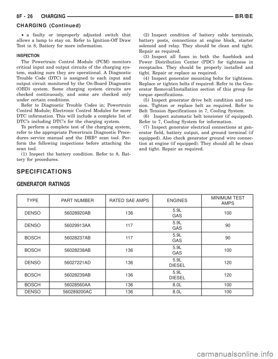
(4) Inspect generator mounting bolts for tightness.
Replace or tighten bolts if required. Refer to the Gen-
erator Removal/Installation section of this group for
torque specifications.
(5) Inspect generator drive belt condition and ten-
sion. Tighten or replace belt as required. Refer to
Belt Tension Specifications in 7, Cooling System.
(6) Inspect automatic belt tensioner (if equipped).
Refer to 7, Cooling System for information.
(7) Inspect generator electrical connections at gen-
erator field, battery output, and ground terminal (if
equipped). Also check generator ground wire connec-
tion at engine (if equipped). They should all be clean
and tight. Repair as required.
SPECIFICATIONS
GENERATOR RATINGS
TYPE PART NUMBER RATED SAE AMPS ENGINESMINIMUM TEST
AMPS
DENSO 56028920AB 1365.9L
GAS100
DENSO 56029913AA 1175.9L
GAS90
BOSCH 56028237AB 1175.9L
GAS90
BOSCH 56028238AB 1365.9L
GAS100
DENSO 56027221AD 1365.9L
DIESEL120
BOSCH 56028239AB 1365.9L
DIESEL120
BOSCH 56028560AA 136 8.0L 100
DENSO 560289200AC 136 8.0L 100
8F - 26 CHARGINGBR/BE
CHARGING (Continued)
Page 416 of 2255
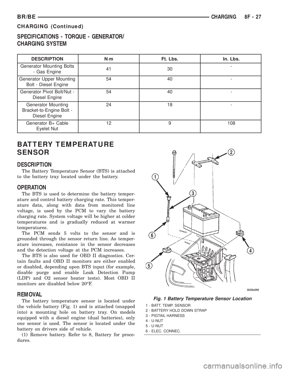
SPECIFICATIONS - TORQUE - GENERATOR/
CHARGING SYSTEM
DESCRIPTION N´m Ft. Lbs. In. Lbs.
Generator Mounting Bolts
- Gas Engine41 30-
Generator Upper Mounting
Bolt - Diesel Engine54 40 -
Generator Pivot Bolt/Nut -
Diesel Engine54 40 -
Generator Mounting
Bracket-to-Engine Bolt -
Diesel Engine24 18 -
Generator B+ Cable
Eyelet Nut12 9 108
BATTERY TEMPERATURE
SENSOR
DESCRIPTION
The Battery Temperature Sensor (BTS) is attached
to the battery tray located under the battery.
OPERATION
The BTS is used to determine the battery temper-
ature and control battery charging rate. This temper-
ature data, along with data from monitored line
voltage, is used by the PCM to vary the battery
charging rate. System voltage will be higher at colder
temperatures and is gradually reduced at warmer
temperatures.
The PCM sends 5 volts to the sensor and is
grounded through the sensor return line. As temper-
ature increases, resistance in the sensor decreases
and the detection voltage at the PCM increases.
The BTS is also used for OBD II diagnostics. Cer-
tain faults and OBD II monitors are either enabled
or disabled, depending upon BTS input (for example,
disable purge and enable Leak Detection Pump
(LDP) and O2 sensor heater tests). Most OBD II
monitors are disabled below 20ÉF.
REMOVAL
The battery temperature sensor is located under
the vehicle battery (Fig. 1) and is attached (snapped
into) a mounting hole on battery tray. On models
equipped with a diesel engine (dual batteries), only
one sensor is used. The sensor is located under the
battery on drivers side of vehicle.
(1) Remove battery. Refer to 8, Battery for proce-
dures.Fig. 1 Battery Temperature Sensor Location
1 - BATT. TEMP. SENSOR
2 - BATTERY HOLD DOWN STRAP
3 - PIGTAIL HARNESS
4 - U-NUT
5 - U-NUT
6 - ELEC. CONNEC.
BR/BECHARGING 8F - 27
CHARGING (Continued)
Page 419 of 2255
INSTALLATION
(1) Position generator to engine and snap field
wire connector into rear of generator.
(2) Install B+ terminal eyelet to generator stud.
Tighten mounting nut to 12 N´m (108 in. lbs.) torque.
(3) Install generator mounting fasteners and
tighten as follows:
²Generator mounting boltÐAll gas powered
enginesÐ41 N´m (30 ft. lbs.) torque.
²Generator pivot bolt/nutÐAll gas powered
enginesÐ41 N´m (30 ft. lbs.) torque.
²Generator mounting boltÐDiesel powered
enginesÐ54 N´m (40 ft. lbs.) torque.
²Generator pivot bolt/nutÐDiesel powered
enginesÐ54 N´m (40 ft. lbs.) torque.
CAUTION: Never force a belt over a pulley rim
using a screwdriver. The synthetic fiber of the belt
can be damaged.
CAUTION: When installing a serpentine accessory
drive belt, the belt MUST be routed correctly. The
water pump will be rotating in the wrong direction if
the belt is installed incorrectly, causing the engine
to overheat. Refer to belt routing label in engine
compartment, or refer to Belt Schematics in Group
7, Cooling System.
(4) Install generator drive belt. Refer to 7, Cooling
System for procedure.
(5) Install negative battery cable(s) to battery(s).
VOLTAGE REGULATOR
DESCRIPTION
The Electronic Voltage Regulator (EVR) is not a
separate component. It is actually a voltage regulat-
ing circuit located within the Powertrain Control
Module (PCM). The EVR is not serviced separately. If
replacement is necessary, the PCM must be replaced.
OPERATION
The amount of direct current produced by the gen-
erator is controlled by EVR circuitry contained
within the PCM. This circuitry is connected in series
with the generators second rotor field terminal and
its ground.
Voltage is regulated by cycling the ground path to
control the strength of the rotor magnetic field. The
EVR circuitry monitors system line voltage (B+) and
battery temperature (refer to Battery Temperature
Sensor for more information). It then determines a
target charging voltage. If sensed battery voltage is
0.5 volts or lower than the target voltage, the PCM
grounds the field winding until sensed battery volt-
age is 0.5 volts above target voltage. A circuit in the
PCM cycles the ground side of the generator field up
to 100 times per second (100Hz), but has the capabil-
ity to ground the field control wire 100% of the time
(full field) to achieve the target voltage. If the charg-
ing rate cannot be monitored (limp-in), a duty cycle
of 25% is used by the PCM in order to have some
generator output. Also refer to Charging System
Operation for additional information.
8F - 30 CHARGINGBR/BE
GENERATOR (Continued)
Page 420 of 2255
STARTING
TABLE OF CONTENTS
page page
STARTING
DESCRIPTION.........................31
OPERATION...........................31
DIAGNOSIS AND TESTING - STARTING
SYSTEM............................32
SPECIFICATIONS
STARTING SYSTEM...................36
SPECIFICATIONS - TORQUE - STARTING
SYSTEM............................37
STARTER MOTOR
DESCRIPTION.........................37OPERATION...........................37
DIAGNOSIS AND TESTING - STARTER
MOTOR .............................38
REMOVAL.............................38
INSTALLATION.........................40
STARTER MOTOR RELAY
DESCRIPTION.........................41
OPERATION...........................41
DIAGNOSIS AND TESTING - STARTER RELAY . 41
REMOVAL.............................42
INSTALLATION.........................42
STARTING
DESCRIPTION
The starting system consists of:
²Starter relay
²Starter motor (including an integral starter sole-
noid)
Other components to be considered as part of start-
ing system are:
²Battery
²Battery cables
²Ignition switch and key lock cylinder
²Clutch pedal position switch (manual transmis-
sion)
²Park/neutral position switch (automatic trans-
mission)
²Wire harnesses and connections.
The Battery, Starting, and Charging systems oper-
ate in conjunction with one another, and must be
tested as a complete system. For correct operation of
starting/charging systems, all components used in
these 3 systems must perform within specifications.
When attempting to diagnose any of these systems, it
is important that you keep their interdependency in
mind.
The diagnostic procedures used in each of these
groups include the most basic conventional diagnostic
methods, to the more sophisticated On-Board Diag-
nostics (OBD) built into the Powertrain Control Mod-
ule (PCM). Use of an induction-type milliampere
ammeter, volt/ohmmeter, battery charger, carbon pile
rheostat (load tester), and 12-volt test lamp may be
required.
Certain starting system components are monitored
by the PCM and may produce a Diagnostic Trouble
Code (DTC). Refer to Emission Control. See Diagnos-tic Trouble Codes for additional information and a
list of codes.OPERATION
The starting system components form two separate
circuits. A high-amperage feed circuit that feeds the
starter motor between 150 and 350 amperes (700
amperes - diesel engine), and a low-amperage control
circuit that operates on less than 20 amperes. The
high-amperage feed circuit components include the
battery, the battery cables, the contact disc portion of
the starter solenoid, and the starter motor. The low-
amperage control circuit components include the igni-
tion switch, the clutch pedal position switch (manual
transmission), the park/neutral position switch (auto-
matic transmission), the starter relay, the electro-
magnetic windings of the starter solenoid, and the
connecting wire harness components.
If the vehicle is equipped with a manual transmis-
sion, it has a clutch pedal position switch installed in
series between the ignition switch and the coil bat-
tery terminal of the starter relay. This normally open
switch prevents the starter relay from being ener-
gized when the ignition switch is turned to the
momentary Start position, unless the clutch pedal is
depressed. This feature prevents starter motor oper-
ation while the clutch disc and the flywheel are
engaged. The starter relay coil ground terminal is
always grounded on vehicles with a manual trans-
mission.
If the vehicle is equipped with an automatic trans-
mission, battery voltage is supplied through the low-
amperage control circuit to the coil battery terminal
of the starter relay when the ignition switch is
turned to the momentary Start position. The park/
neutral position switch is installed in series between
the starter relay coil ground terminal and ground.
BR/BESTARTING 8F - 31
Page 446 of 2255
ical dimensions are smaller than those of the conven-
tional ISO relay.
The heated seat relay cannot be repaired or
adjusted and, if faulty or damaged, it must be
replaced.
OPERATION
The ISO relay consists of an electromagnetic coil, a
resistor or diode, and three (two fixed and one mov-
able) electrical contacts. The movable (common feed)
relay contact is held against one of the fixed contacts
(normally closed) by spring pressure. When the elec-
tromagnetic coil is energized, it draws the movable
contact away from the normally closed fixed contact,
and holds it against the other (normally open) fixed
contact. When the electromagnetic coil is de-ener-
gized, spring pressure returns the movable contact to
the normally closed position. The resistor or diode is
connected in parallel with the electromagnetic coil in
the relay, and helps to dissipate voltage spikes that
are produced when the coil is de-energized.
The heated seat relay is controlled by the premium
version of the Central Timer Module (CTM), which
controls the ground feed to the coil ground terminal
of the relay to energize and de-energize the electro-
magnetic coil of the relay. The CTM monitors engine
operation through messages it receives from the Pow-
ertrain Control Module (PCM) over the Chrysler Col-
lision Detection (CCD) data bus network. The CTM is
programmed to energize the relay only when the
engine is running, and to de-energize the relay when
the engine is not running. Refer toCentral Timer
Modulein the index of this service manual for the
location of more information on the premium CTM.
DIAGNOSIS AND TESTING - HEATED SEAT
RELAY
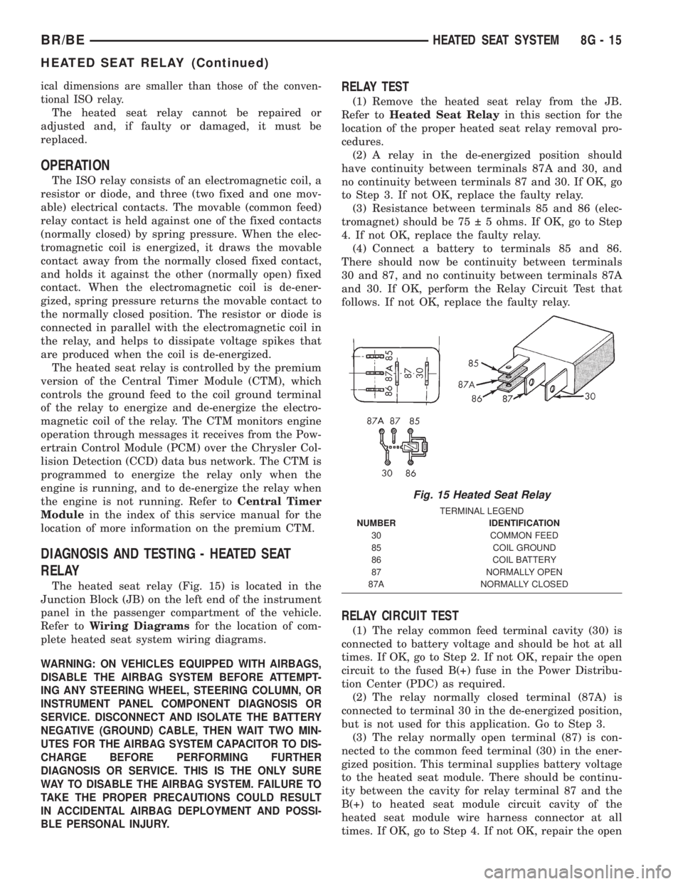
The heated seat relay (Fig. 15) is located in the
Junction Block (JB) on the left end of the instrument
panel in the passenger compartment of the vehicle.
Refer toWiring Diagramsfor the location of com-
plete heated seat system wiring diagrams.
WARNING: ON VEHICLES EQUIPPED WITH AIRBAGS,
DISABLE THE AIRBAG SYSTEM BEFORE ATTEMPT-
ING ANY STEERING WHEEL, STEERING COLUMN, OR
INSTRUMENT PANEL COMPONENT DIAGNOSIS OR
SERVICE. DISCONNECT AND ISOLATE THE BATTERY
NEGATIVE (GROUND) CABLE, THEN WAIT TWO MIN-
UTES FOR THE AIRBAG SYSTEM CAPACITOR TO DIS-
CHARGE BEFORE PERFORMING FURTHER
DIAGNOSIS OR SERVICE. THIS IS THE ONLY SURE
WAY TO DISABLE THE AIRBAG SYSTEM. FAILURE TO
TAKE THE PROPER PRECAUTIONS COULD RESULT
IN ACCIDENTAL AIRBAG DEPLOYMENT AND POSSI-
BLE PERSONAL INJURY.
RELAY TEST
(1) Remove the heated seat relay from the JB.
Refer toHeated Seat Relayin this section for the
location of the proper heated seat relay removal pro-
cedures.
(2) A relay in the de-energized position should
have continuity between terminals 87A and 30, and
no continuity between terminals 87 and 30. If OK, go
to Step 3. If not OK, replace the faulty relay.
(3) Resistance between terminals 85 and 86 (elec-
tromagnet) should be 75 5 ohms. If OK, go to Step
4. If not OK, replace the faulty relay.
(4) Connect a battery to terminals 85 and 86.
There should now be continuity between terminals
30 and 87, and no continuity between terminals 87A
and 30. If OK, perform the Relay Circuit Test that
follows. If not OK, replace the faulty relay.
RELAY CIRCUIT TEST
(1) The relay common feed terminal cavity (30) is
connected to battery voltage and should be hot at all
times. If OK, go to Step 2. If not OK, repair the open
circuit to the fused B(+) fuse in the Power Distribu-
tion Center (PDC) as required.
(2) The relay normally closed terminal (87A) is
connected to terminal 30 in the de-energized position,
but is not used for this application. Go to Step 3.
(3) The relay normally open terminal (87) is con-
nected to the common feed terminal (30) in the ener-
gized position. This terminal supplies battery voltage
to the heated seat module. There should be continu-
ity between the cavity for relay terminal 87 and the
B(+) to heated seat module circuit cavity of the
heated seat module wire harness connector at all
times. If OK, go to Step 4. If not OK, repair the open
Fig. 15 Heated Seat Relay
TERMINAL LEGEND
NUMBER IDENTIFICATION
30 COMMON FEED
85 COIL GROUND
86 COIL BATTERY
87 NORMALLY OPEN
87A NORMALLY CLOSED
BR/BEHEATED SEAT SYSTEM 8G - 15
HEATED SEAT RELAY (Continued)
Page 447 of 2255
B(+) to heated seat module circuit to the heated seat
module as required.
(4) The coil battery terminal (86) is connected to
the electromagnet in the relay. It is connected to bat-
tery voltage and should be hot at all times. Check for
battery voltage at the cavity for relay terminal 86. If
OK, go to Step 5. If not OK, repair the open circuit to
the fused B(+) fuse in the PDC as required.
(5) The coil ground terminal (85) is connected to
the electromagnet in the relay. It is grounded by the
premium version of the Central Timer Module (CTM)
in response to an engine speed message received over
the Chrysler Collision Detection (CCD) data bus from
the Powertrain Control Module (PCM) when the
engine is running. Check for continuity between the
cavity for relay terminal 85 and the heated seat relay
control circuit cavity of the CTM wire harness con-
nector. There should be continuity at all times. If OK,
use a DRBIIItscan tool and the proper diagnostic
procedures manual to test the operation of the CTM
and CCD data bus. If not OK, repair the open heated
seat relay control circuit as required.
REMOVAL
(1) Disconnect and isolate the battery negative
cable.
(2) Remove the fuse access panel by inserting a
finger in the finger recess molded into the panel and
then pulling the panel sharply away from the left
outboard end of the instrument panel.
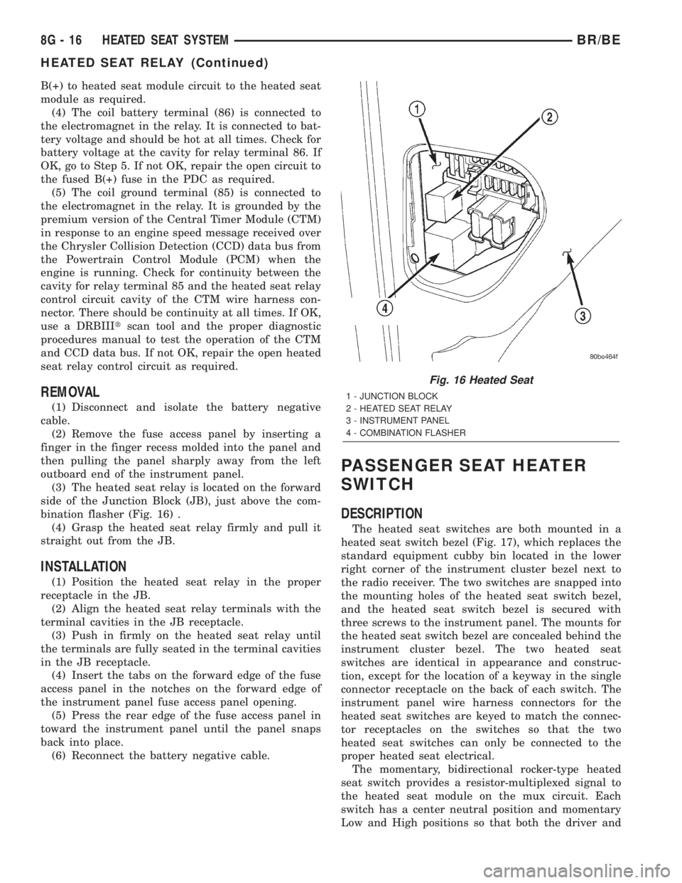
(3) The heated seat relay is located on the forward
side of the Junction Block (JB), just above the com-
bination flasher (Fig. 16) .
(4) Grasp the heated seat relay firmly and pull it
straight out from the JB.
INSTALLATION
(1) Position the heated seat relay in the proper
receptacle in the JB.
(2) Align the heated seat relay terminals with the
terminal cavities in the JB receptacle.
(3) Push in firmly on the heated seat relay until
the terminals are fully seated in the terminal cavities
in the JB receptacle.
(4) Insert the tabs on the forward edge of the fuse
access panel in the notches on the forward edge of
the instrument panel fuse access panel opening.
(5) Press the rear edge of the fuse access panel in
toward the instrument panel until the panel snaps
back into place.
(6) Reconnect the battery negative cable.
PASSENGER SEAT HEATER
SWITCH
DESCRIPTION
The heated seat switches are both mounted in a
heated seat switch bezel (Fig. 17), which replaces the
standard equipment cubby bin located in the lower
right corner of the instrument cluster bezel next to
the radio receiver. The two switches are snapped into
the mounting holes of the heated seat switch bezel,
and the heated seat switch bezel is secured with
three screws to the instrument panel. The mounts for
the heated seat switch bezel are concealed behind the
instrument cluster bezel. The two heated seat
switches are identical in appearance and construc-
tion, except for the location of a keyway in the single
connector receptacle on the back of each switch. The
instrument panel wire harness connectors for the
heated seat switches are keyed to match the connec-
tor receptacles on the switches so that the two
heated seat switches can only be connected to the
proper heated seat electrical.
The momentary, bidirectional rocker-type heated
seat switch provides a resistor-multiplexed signal to
the heated seat module on the mux circuit. Each
switch has a center neutral position and momentary
Low and High positions so that both the driver and
Fig. 16 Heated Seat
1 - JUNCTION BLOCK
2 - HEATED SEAT RELAY
3 - INSTRUMENT PANEL
4 - COMBINATION FLASHER
8G - 16 HEATED SEAT SYSTEMBR/BE
HEATED SEAT RELAY (Continued)
Page 458 of 2255
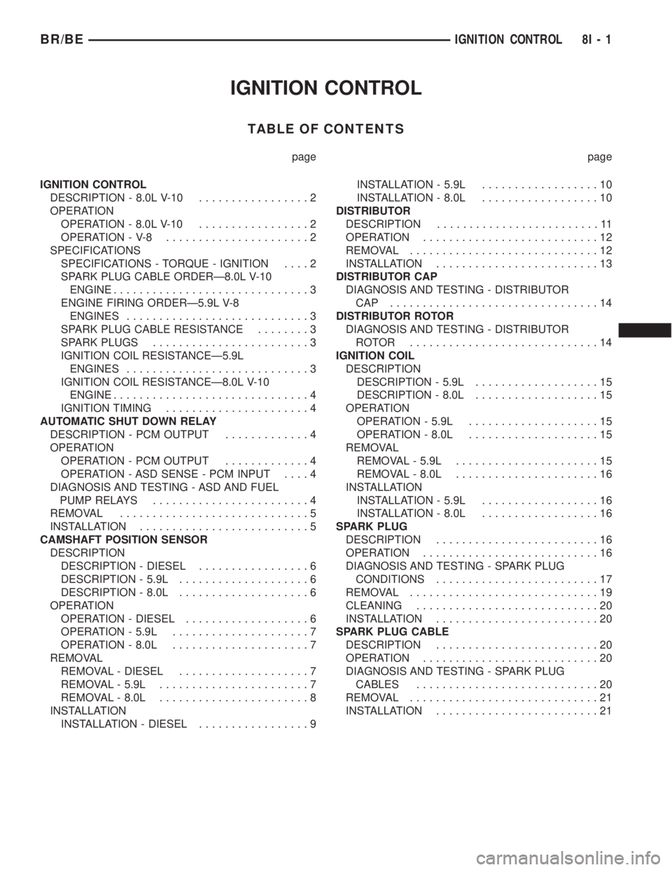
IGNITION CONTROL
TABLE OF CONTENTS
page page
IGNITION CONTROL
DESCRIPTION - 8.0L V-10.................2
OPERATION
OPERATION - 8.0L V-10.................2
OPERATION - V-8......................2
SPECIFICATIONS
SPECIFICATIONS - TORQUE - IGNITION....2
SPARK PLUG CABLE ORDERÐ8.0L V-10
ENGINE..............................3
ENGINE FIRING ORDERÐ5.9L V-8
ENGINES............................3
SPARK PLUG CABLE RESISTANCE........3
SPARK PLUGS........................3
IGNITION COIL RESISTANCEÐ5.9L
ENGINES............................3
IGNITION COIL RESISTANCEÐ8.0L V-10
ENGINE..............................4
IGNITION TIMING......................4
AUTOMATIC SHUT DOWN RELAY
DESCRIPTION - PCM OUTPUT.............4
OPERATION
OPERATION - PCM OUTPUT.............4
OPERATION - ASD SENSE - PCM INPUT....4
DIAGNOSIS AND TESTING - ASD AND FUEL
PUMP RELAYS........................4
REMOVAL.............................5
INSTALLATION..........................5
CAMSHAFT POSITION SENSOR
DESCRIPTION
DESCRIPTION - DIESEL.................6
DESCRIPTION - 5.9L....................6
DESCRIPTION - 8.0L....................6
OPERATION
OPERATION - DIESEL...................6
OPERATION - 5.9L.....................7
OPERATION - 8.0L.....................7
REMOVAL
REMOVAL - DIESEL....................7
REMOVAL - 5.9L.......................7
REMOVAL - 8.0L.......................8
INSTALLATION
INSTALLATION - DIESEL.................9INSTALLATION - 5.9L..................10
INSTALLATION - 8.0L..................10
DISTRIBUTOR
DESCRIPTION.........................11
OPERATION...........................12
REMOVAL.............................12
INSTALLATION.........................13
DISTRIBUTOR CAP
DIAGNOSIS AND TESTING - DISTRIBUTOR
CAP ................................14
DISTRIBUTOR ROTOR
DIAGNOSIS AND TESTING - DISTRIBUTOR
ROTOR .............................14
IGNITION COIL
DESCRIPTION
DESCRIPTION - 5.9L...................15
DESCRIPTION - 8.0L...................15
OPERATION
OPERATION - 5.9L....................15
OPERATION - 8.0L....................15
REMOVAL
REMOVAL - 5.9L......................15
REMOVAL - 8.0L......................16
INSTALLATION
INSTALLATION - 5.9L..................16
INSTALLATION - 8.0L..................16
SPARK PLUG
DESCRIPTION.........................16
OPERATION...........................16
DIAGNOSIS AND TESTING - SPARK PLUG
CONDITIONS.........................17
REMOVAL.............................19
CLEANING............................20
INSTALLATION.........................20
SPARK PLUG CABLE
DESCRIPTION.........................20
OPERATION...........................20
DIAGNOSIS AND TESTING - SPARK PLUG
CABLES............................20
REMOVAL.............................21
INSTALLATION.........................21
BR/BEIGNITION CONTROL 8I - 1
Page 459 of 2255
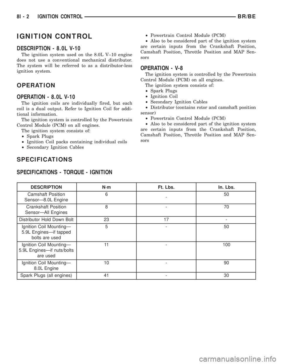
IGNITION CONTROL
DESCRIPTION - 8.0L V-10
The ignition system used on the 8.0L V±10 engine
does not use a conventional mechanical distributor.
The system will be referred to as a distributor-less
ignition system.
OPERATION
OPERATION - 8.0L V-10
The ignition coils are individually fired, but each
coil is a dual output. Refer to Ignition Coil for addi-
tional information.
The ignition system is controlled by the Powertrain
Control Module (PCM) on all engines.
The ignition system consists of:
²Spark Plugs
²Ignition Coil packs containing individual coils
²Secondary Ignition Cables²Powertrain Control Module (PCM)
²Also to be considered part of the ignition system
are certain inputs from the Crankshaft Position,
Camshaft Position, Throttle Position and MAP Sen-
sors
OPERATION - V-8
The ignition system is controlled by the Powertrain
Control Module (PCM) on all engines.
The ignition system consists of:
²Spark Plugs
²Ignition Coil
²Secondary Ignition Cables
²Distributor (contains rotor and camshaft position
sensor)
²Powertrain Control Module (PCM)
²Also to be considered part of the ignition system
are certain inputs from the Crankshaft Position,
Camshaft Position, Throttle Position and MAP Sen-
sors
SPECIFICATIONS
SPECIFICATIONS - TORQUE - IGNITION
DESCRIPTION N´m Ft. Lbs. In. Lbs.
Camshaft Position
SensorÐ8.0L Engine6
-50
Crankshaft Position
SensorÐAll Engines8-70
Distributor Hold Down Bolt 23 17 -
Ignition Coil MountingÐ
5.9L EnginesÐif tapped
bolts are used5-50
Ignition Coil MountingÐ
5.9L EnginesÐif nuts/bolts
are used11 - 100
Ignition Coil MountingÐ
8.0L Engine10 - 90
Spark Plugs (all engines) 41 - 30
8I - 2 IGNITION CONTROLBR/BE