PCM DODGE RAM 2002 Service Manual PDF
[x] Cancel search | Manufacturer: DODGE, Model Year: 2002, Model line: RAM, Model: DODGE RAM 2002Pages: 2255, PDF Size: 62.07 MB
Page 629 of 2255
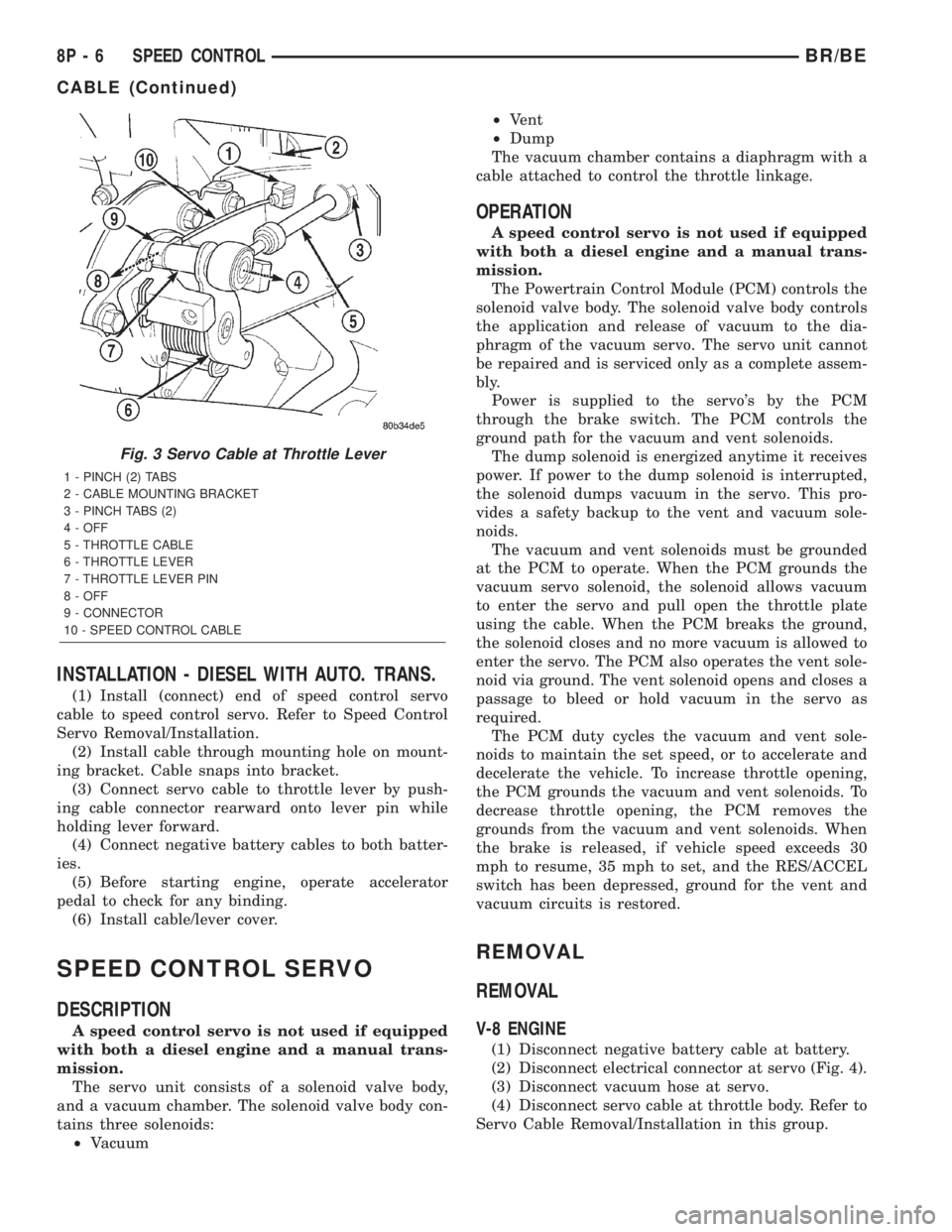
INSTALLATION - DIESEL WITH AUTO. TRANS.
(1) Install (connect) end of speed control servo
cable to speed control servo. Refer to Speed Control
Servo Removal/Installation.
(2) Install cable through mounting hole on mount-
ing bracket. Cable snaps into bracket.
(3) Connect servo cable to throttle lever by push-
ing cable connector rearward onto lever pin while
holding lever forward.
(4) Connect negative battery cables to both batter-
ies.
(5) Before starting engine, operate accelerator
pedal to check for any binding.
(6) Install cable/lever cover.
SPEED CONTROL SERVO
DESCRIPTION
A speed control servo is not used if equipped
with both a diesel engine and a manual trans-
mission.
The servo unit consists of a solenoid valve body,
and a vacuum chamber. The solenoid valve body con-
tains three solenoids:
²Vacuum²Vent
²Dump
The vacuum chamber contains a diaphragm with a
cable attached to control the throttle linkage.
OPERATION
A speed control servo is not used if equipped
with both a diesel engine and a manual trans-
mission.
The Powertrain Control Module (PCM) controls the
solenoid valve body. The solenoid valve body controls
the application and release of vacuum to the dia-
phragm of the vacuum servo. The servo unit cannot
be repaired and is serviced only as a complete assem-
bly.
Power is supplied to the servo's by the PCM
through the brake switch. The PCM controls the
ground path for the vacuum and vent solenoids.
The dump solenoid is energized anytime it receives
power. If power to the dump solenoid is interrupted,
the solenoid dumps vacuum in the servo. This pro-
vides a safety backup to the vent and vacuum sole-
noids.
The vacuum and vent solenoids must be grounded
at the PCM to operate. When the PCM grounds the
vacuum servo solenoid, the solenoid allows vacuum
to enter the servo and pull open the throttle plate
using the cable. When the PCM breaks the ground,
the solenoid closes and no more vacuum is allowed to
enter the servo. The PCM also operates the vent sole-
noid via ground. The vent solenoid opens and closes a
passage to bleed or hold vacuum in the servo as
required.
The PCM duty cycles the vacuum and vent sole-
noids to maintain the set speed, or to accelerate and
decelerate the vehicle. To increase throttle opening,
the PCM grounds the vacuum and vent solenoids. To
decrease throttle opening, the PCM removes the
grounds from the vacuum and vent solenoids. When
the brake is released, if vehicle speed exceeds 30
mph to resume, 35 mph to set, and the RES/ACCEL
switch has been depressed, ground for the vent and
vacuum circuits is restored.
REMOVAL
REMOVAL
V-8 ENGINE
(1) Disconnect negative battery cable at battery.
(2) Disconnect electrical connector at servo (Fig. 4).
(3) Disconnect vacuum hose at servo.
(4) Disconnect servo cable at throttle body. Refer to
Servo Cable Removal/Installation in this group.
Fig. 3 Servo Cable at Throttle Lever
1 - PINCH (2) TABS
2 - CABLE MOUNTING BRACKET
3 - PINCH TABS (2)
4 - OFF
5 - THROTTLE CABLE
6 - THROTTLE LEVER
7 - THROTTLE LEVER PIN
8 - OFF
9 - CONNECTOR
10 - SPEED CONTROL CABLE
8P - 6 SPEED CONTROLBR/BE
CABLE (Continued)
Page 635 of 2255
(4) Insert servo studs through holes in servo cable
sleeve.
(5) Install servo mounting nuts and tighten to 8.5
N´m (75 in. lbs.) torque.
(6) Connect vacuum line to servo.
(7) Connect electrical connector to servo terminals.
(8) Connect servo cable to throttle body. Refer to
Servo Cable Removal/Installation in this group.
(9) Install battery tray. Tighten all battery tray
mounting hardware to 16 N´m (140 in. lbs.) torque.
(10) Position battery into battery tray.
(11) If equipped, install battery heat shield.
(12) Install battery holddown clamp. Tighten bolt
to 4 N´m (35 in. lbs.) torque.
(13) Connect positive battery cable to battery.
(14) Connect negative battery cable to battery.
(15) Before starting engine, operate accelerator
pedal to check for any binding.
INSTALLATION - DIESEL WITH AUTO. TRANS.
(1) Position servo to mounting bracket.
(2) Align hole in cable connector with hole in servo
pin. Install cable-to-servo retaining clip.
(3) Insert servo studs through holes in servo
mounting bracket.
(4) Insert servo studs through holes in servo cable
sleeve.
(5) Install servo mounting nuts and tighten to 8.5
N´m (75 in. lbs.) torque.
(6) Connect vacuum line to servo.
(7) Connect electrical connector to servo terminals.
(8) Connect servo cable to throttle lever by push-
ing cable connector rearward onto lever pin while
holding lever forward.
(9) Install battery tray. Tighten all battery tray
mounting hardware to 16 N´m (140 in. lbs.) torque.
(10) Position battery into battery tray.
(11) If equipped, install battery heat shield.
(12) Install battery holddown clamp. Tighten bolt
to 4 N´m (35 in. lbs.) torque.
(13) Connect positive battery cable to battery.
(14) Connect negative battery cables to both bat-
teries.
(15) Before starting engine, operate accelerator
pedal to check for any binding.
(16) Install cable/lever cover.
SWITCH
DESCRIPTION
Gas Engines and Diesel With Auto. Trans.
There are two separate switch pods that operate
the speed control system. The steering-wheel-
mounted switches use multiplexed circuits to provideinputs to the Powertrain Control Module (PCM) for
ON, OFF, RESUME, ACCELERATE, SET, DECEL
and CANCEL modes. Refer to the owner's manual for
more information on speed control switch functions
and setting procedures.
The individual switches cannot be repaired. If one
switch fails, the entire switch module must be
replaced.
Diesel With Manual Trans.
There are two separate switch pods that operate
the speed control system. The steering-wheel-
mounted switches use multiplexed circuits to provide
inputs to the Engine Control Module (ECM) for ON,
OFF, RESUME, ACCELERATE, SET, DECEL and
CANCEL modes. Refer to the owner's manual for
more information on speed control switch functions
and setting procedures.
The individual switches cannot be repaired. If one
switch fails, the entire switch module must be
replaced.
OPERATION
Gas Engines and Diesel With Auto. Trans.
When speed control is selected by depressing the
ON, OFF switch, the Powertrain Control Module
(PCM) allows a set speed to be stored in its RAM for
speed control. To store a set speed, depress the SET
switch while the vehicle is moving at a speed
between approximately 35 and 85 mph. In order for
the speed control to engage, the brakes cannot be
applied, nor can the gear selector be indicating the
transmission is in Park or Neutral.
The speed control can be disengaged manually by:
²Stepping on the brake pedal.
²Depressing the OFF switch.
²Depressing the CANCEL switch.
The speed control can be disengaged also by any of
the following conditions:
²An indication of Park or Neutral.
²The vehicle speed signal increases at a rate of
10 mph per second (indicates that the co-efficient of
friction between the road surface and tires is
extremely low).
²Depressing the clutch pedal.
²Excessive engine rpm (indicates that the trans-
mission may be in a low gear).
²The vehicle speed signal decreases at a rate of
10 mph per second (indicates that the vehicle may
have decelerated at an extremely high rate).
²If the actual speed is not within 20 mph of the
set speed.
The previous disengagement conditions are pro-
grammed for added safety.
8P - 12 SPEED CONTROLBR/BE
SPEED CONTROL SERVO (Continued)
Page 636 of 2255
Once the speed control has been disengaged,
depressing the ACCEL switch restores the vehicle to
the target speed that was stored in the PCM's RAM.
NOTE: Depressing the OFF switch will erase the set
speed stored in the PCM's RAM.
If, while the speed control is engaged, the driver
wishes to increase vehicle speed, the PCM is pro-
grammed for an acceleration feature. With the
ACCEL switch held closed, the vehicle accelerates
slowly to the desired speed. The new target speed is
stored in the PCM's RAM when the ACCEL switch is
released. The PCM also has a9tap-up9feature in
which vehicle speed increases at a rate of approxi-
mately 2 mph for each momentary switch activation
of the ACCEL switch.
The PCM also provides a means to decelerate with-
out disengaging speed control. To decelerate from an
existing recorded target speed, depress and hold the
COAST switch until the desired speed is reached.
Then release the switch. The ON, OFF switch oper-
ates two components: the PCM's ON, OFF input, and
the battery voltage to the brake switch, which powers
the speed control servo.
Diesel With Manual Trans.
When speed control is selected by depressing the
ON, OFF switch, the Engine Control Module (ECM)
allows a set speed to be stored in its RAM for speed
control. To store a set speed, depress the SET switch
while the vehicle is moving at a speed between
approximately 35 and 85 mph. In order for the speed
control to engage, the brakes cannot be applied.
The speed control can be disengaged manually by:
²Stepping on the brake pedal.
²Depressing the OFF switch.
²Depressing the CANCEL switch.
The speed control can be disengaged also by any of
the following conditions:
²The vehicle speed signal increases at a rate of
10 mph per second (indicates that the co-efficient of
friction between the road surface and tires is
extremely low).
²Depressing the clutch pedal.
²Excessive engine rpm (indicates that the trans-
mission may be in a low gear).
²The vehicle speed signal decreases at a rate of
10 mph per second (indicates that the vehicle may
have decelerated at an extremely high rate).
²If the actual speed is not within 20 mph of the
set speed.The previous disengagement conditions are pro-
grammed for added safety.
Once the speed control has been disengaged,
depressing the ACCEL switch restores the vehicle to
the target speed that was stored in the ECM's RAM.
NOTE: Depressing the OFF switch will erase the set
speed stored in the ECM's RAM.
If, while the speed control is engaged, the driver
wishes to increase vehicle speed, the ECM is pro-
grammed for an acceleration feature. With the
ACCEL switch held closed, the vehicle accelerates
slowly to the desired speed. The new target speed is
stored in the ECM's RAM when the ACCEL switch is
released. The ECM also has a9tap-up9feature in
which vehicle speed increases at a rate of approxi-
mately 2 mph for each momentary switch activation
of the ACCEL switch.
The ECM also provides a means to decelerate with-
out disengaging speed control. To decelerate from an
existing recorded target speed, depress and hold the
COAST switch until the desired speed is reached.
Then release the switch. The ON, OFF switch oper-
ates two components: the ECM's ON, OFF input, and
the battery voltage to the brake switch, which powers
the speed control servo.
REMOVAL
WARNING: BEFORE BEGINNING ANY AIRBAG SYS-
TEM COMPONENT REMOVAL OR INSTALLATION,
REMOVE AND ISOLATE THE NEGATIVE (-)
CABLE(S) FROM THE BATTERY. THIS IS THE ONLY
SURE WAY TO DISABLE THE AIRBAG SYSTEM.
THEN WAIT TWO MINUTES FOR SYSTEM CAPACI-
TOR TO DISCHARGE BEFORE FURTHER SYSTEM
SERVICE. FAILURE TO DO THIS COULD RESULT IN
ACCIDENTAL AIRBAG DEPLOYMENT AND POSSI-
BLE INJURY.
(1) Disconnect and isolate negative battery
cable(s).
(2) Remove airbag module. Refer to 8, Restraint
Systems for procedures.
(3) Remove switch-to-steering wheel mounting
screws (Fig. 20).
(4) Remove switch.
(5) Remove electrical connector at switch.
BR/BESPEED CONTROL 8P - 13
SWITCH (Continued)
Page 640 of 2255
VEHICLE THEFT SECURITY
TABLE OF CONTENTS
page page
VEHICLE THEFT SECURITY
DESCRIPTION..........................1
OPERATION............................2
DIAGNOSIS AND TESTING - VEHICLE THEFT
SECURITY SYSTEM....................3VTSS INDICATOR
DESCRIPTION..........................3
OPERATION............................3
DIAGNOSIS AND TESTING - VTSS
INDICATOR...........................4
VEHICLE THEFT SECURITY
DESCRIPTION
The Vehicle Theft Security System (VTSS) is an
available factory-installed option on this model when
it is also equipped with the high-line or premium
Central Timer Module (CTM). The VTSS is designed
to provide perimeter protection against unauthorized
use or tampering by monitoring the vehicle doors and
the ignition system. If unauthorized vehicle use or
tampering is detected, the system responds by puls-
ing the horn, flashing the headlamps, and preventing
the engine from operating.
The VTSS includes the following major compo-
nents, which are described in further detail else-
where in this service manual:
²Central Timer Module- The high-line or pre-
mium Central Timer Module (CTM) is located under
the driver side end of the instrument panel, inboard
of the instrument panel steering column opening.
The high-line or premium CTM contains a micropro-
cessor and software that allow it to provide many
electronic functions and features not available with
base version of the CTM, including the VTSS. The
CTM provides all of the proper VTSS features and
outputs based upon the monitored inputs. The CTM
circuitry monitors hard wired switch inputs, as well
as message inputs received from other vehicle elec-
tronic modules over the Chrysler Collision Detection
(CCD) data bus network. (Refer to 8 - ELECTRICAL/
ELECTRONIC CONTROL MODULES/BODY CON-
TROL/CENTRAL TIMER MODULE -
DESCRIPTION).
²Door Ajar Switch- A door ajar switch is
located on the hinge pillar of each front door in the
vehicle. These switches provide an input to the VTSS
indicating whether the door is opened or closed.
(Refer to 8 - ELECTRICAL/LAMPS/LIGHTING -
INTERIOR/DOOR AJAR SWITCH - DESCRIPTION).
²Door Cylinder Lock Switch- A door cylinder
lock switch is located on the back of each front door
lock cylinder. This switch provides an input to theVTSS indicating whether the system should remain
armed or be disarmed. (Refer to 8 - ELECTRICAL/
POWER LOCKS/DOOR CYLINDER LOCK SWITCH
- DESCRIPTION).
²Horn Relay- The horn relay is located in the
Power Distribution Center (PDC) in the engine com-
partment near the battery. The horn relay is nor-
mally activated by the horn switch to control the
sounding of the vehicle horn or horns. However, it
can also be activated by an output of the Central
Timer Module (CTM) to provide an audible indication
that unauthorized vehicle use or tampering has been
detected. (Refer to 8 - ELECTRICAL/HORN/HORN
RELAY - DESCRIPTION).
²Headlamp Relay- The headlamp relay (also
known as the security relay) is located in the Power
Distribution Center (PDC) in the engine compart-
ment near the battery. The headlamp relay is nor-
mally activated by the Central Timer Module (CTM)
based upon inputs from the Remote Keyless Entry
(RKE) panic mode feature. However, it can also be
activated by an output of the CTM to flash the head-
lamp low beams to provide a highly visible indication
that unauthorized vehicle use or tampering has been
detected. (Refer to 8 - ELECTRICAL/LAMPS/LIGHT-
ING - EXTERIOR/HEADLAMP RELAY - DESCRIP-
TION).
²VTSS Indicator- A red Light Emitting Diode
(LED) located on the lower surface of the overhead
console near the windshield is illuminated by an out-
put of the Central Timer Module (CTM) to indicate
the status of the VTSS. This LED is integral to the
electronic circuit board for the Compass Mini-Trip
Computer (CMTC). (Refer to 8 - ELECTRICAL/
OVERHEAD CONSOLE/COMPASS/MINI-TRIP
COMPUTER - DESCRIPTION).
The engine no-run feature of the VTSS relies upon
communication between the high-line or premium
CTM and the Powertrain Control Module (PCM) over
the Chrysler Collision Detection (CCD) data bus net-
work.
BR/BEVEHICLE THEFT SECURITY 8Q - 1
Page 641 of 2255
Hard wired circuitry connects many of the VTSS
components to each other through the electrical sys-
tem of the vehicle. These hard wired circuits are
integral to several wire harnesses, which are routed
throughout the vehicle and retained by many differ-
ent methods. These circuits may be connected to each
other, to the vehicle electrical system and to the
VTSS components through the use of a combination
of soldered splices, splice block connectors, and many
different types of wire harness terminal connectors
and insulators. Refer to the appropriate wiring infor-
mation. The wiring information includes wiring dia-
grams, proper wire and connector repair procedures,
further details on wire harness routing and reten-
tion, as well as pin-out and location views for the
various wire harness connectors, splices and grounds.
OPERATION
A Central Timer Module (CTM) is used on this
model to control and integrate many of the electronic
functions and features included in the Vehicle Theft
Security System (VTSS). In the VTSS, the CTM
receives inputs indicating the status of the door ajar
switches, the door cylinder lock switch, and the igni-
tion switch. The programming in the CTM allows it
to process the information from all of these inputs
and send control outputs to energize or de-energize
the horn relay, the headlamp relay, and the VTSS
indicator. The control of these inputs and outputs are
what constitute all of the features of the VTSS. Fol-
lowing is information on the operation of each of the
VTSS features. Refer to the owner's manual in the
vehicle glove box for more information on the fea-
tures, use and operation of the VTSS.
ENABLING
The high-line or premium version of the CTM must
have the VTSS function electronically enabled in
order for the VTSS to perform as designed. The logic
in the CTM keeps its VTSS function dormant until it
is enabled using a DRBIIItscan tool. The VTSS
function of the high-line or premium CTM is enabled
on vehicles equipped with the VTSS option at the
factory, but a service replacement CTM must be
VTSS-enabled by the dealer using a DRBIIItscan
tool. Refer to the appropriate diagnostic information.
The VTSS engine no-run feature is disabled when
it is shipped from the factory. This is done by pro-
gramming within the Powertrain Control Module
(PCM). The logic in the PCM prevents the VTSS
engine no-run feature from arming until the engine
start counter within the PCM sees twenty enginestarts. The VTSS no-run feature must be enabled by
the dealer when the vehicle is received from the
assembly plant. Once the VTSS engine no-run fea-
ture has been enabled, it cannot be disabled unless
the PCM is replaced with a new unit. The same
VTSS engine no-run feature enable logic will apply
anytime the PCM is replaced with a new unit.
ARMING
Passive arming of the VTSS occurs when the vehi-
cle is exited with the key removed from the ignition
switch, the headlamps are turned off, and the doors
are locked while they are open using the power lock
switch, or locked after they are closed by turning
either front door lock cylinder to the lock position
using the key. The power lock switch will not func-
tion if the key is in the ignition switch or the head-
lamps are turned on with the driver side front door
open. The VTSS will not arm if the doors are locked
using the mechanical lock button. Active arming of
the VTSS occurs when the ªLockº button on the
Remote Keyless Entry (RKE) transmitter is
depressed to lock the vehicle. For active arming to
occur, the doors must be closed and the ignition
switch must be in the Off position when the RKE
transmitter ªLockº button is depressed. However,
once the VTSS arming process has been completed,
the ignition switch can be turned to the Accessory
position without triggering the alarm.
Once the VTSS begins passive or active arming,
the security indicator lamp in the overhead console
will flash rapidly for about fifteen seconds. This indi-
cates that the VTSS arming is in progress. Turning a
key in the ignition switch, opening a door, or unlock-
ing a door by any means during the fifteen second
arming process will cause the VTSS indicator to stop
flashing and the arming process to abort. Once the
fifteen second arming function is successfully com-
pleted, the indicator will flash at a slower rate, indi-
cating that the VTSS is armed.
DISARMING
Passive disarming of the VTSS occurs when the
vehicle is unlocked using the key to unlock either
front door. Active disarming of the VTSS occurs when
the vehicle is unlocked by depressing the ªUnlockº
button of the RKE transmitter. Once the alarm has
been activated (horn pulsing, headlamps flashing,
and the engine no-run feature), either disarming
method will also deactivate the alarm. Depressing
the ªPanicº button on the RKE transmitter willnot
disarm the VTSS.
8Q - 2 VEHICLE THEFT SECURITYBR/BE
VEHICLE THEFT SECURITY (Continued)
Page 642 of 2255
POWER-UP MODE
When the armed VTSS senses that the battery has
been disconnected and reconnected, it enters its pow-
er-up mode. In the power-up mode the alarm system
remains armed following a battery failure or discon-
nect. If the VTSS was armed prior to a battery dis-
connect or failure, the technician or vehicle operator
will have to actively or passively disarm the alarm
system after the battery is reconnected. The pow-
er-up mode will also apply if the battery goes dead
while the system is armed, and battery jump-starting
is attempted. The engine no-run feature will prevent
the engine from starting until the alarm system has
been actively or passively disarmed. The VTSS will
be armed until the technician or vehicle operator has
actively or passively disarmed the alarm system. If
the VTSS is in the disarmed mode prior to a battery
disconnect or failure, it will remain disarmed after
the battery is reconnected or replaced, or if jump-
starting is attempted.
TAMPER ALERT
The VTSS tamper alert feature will sound the horn
three times upon disarming, if the alarm was trig-
gered and has since timed-out (about fifteen min-
utes). This feature alerts the vehicle operator that
the VTSS alarm was activated while the vehicle was
unattended.
DIAGNOSIS AND TESTING - VEHICLE THEFT
SECURITY SYSTEM
The VTSS-related hard wired inputs to and out-
puts from the high-line or premium Central Timer
Module (CTM) may be diagnosed and tested using
conventional diagnostic tools and procedures. Refer
to the appropriate wiring information. The wiring
information includes wiring diagrams, proper wire
and connector repair procedures, further details on
wire harness routing and retention, as well as pin-
out and location views for the various wire harness
connectors, splices and grounds.
However, conventional diagnostic methods may not
prove conclusive in the diagnosis of the CTM, the
Powertrain Control Module (PCM), or the Chrysler
Collision Detection (CCD) data bus network. In order
to obtain conclusive testing of the VTSS, the CTM,
the PCM, and the CCD data bus network must also
be checked. The most reliable, efficient, and accurate
means to diagnose the VTSS requires the use of a
DRBIIItscan tool. Refer to the appropriate diagnos-
tic information. The DRBIIItscan tool can provide
confirmation that the CCD data bus network is func-
tional, that all of the electronic modules are sending
and receiving the proper messages over the CCD
data bus, and that these modules are receiving the
proper hard wired inputs and responding with theproper hard wired outputs needed to perform their
functions. See the ªVehicle Theft Security Systemº
menu item on the DRBIIItscan tool.
WARNING: ON VEHICLES EQUIPPED WITH AIR-
BAGS, DISABLE THE AIRBAG SYSTEM BEFORE
ATTEMPTING ANY STEERING WHEEL, STEERING
COLUMN, OR INSTRUMENT PANEL COMPONENT
DIAGNOSIS OR SERVICE. DISCONNECT AND ISO-
LATE THE BATTERY NEGATIVE (GROUND) CABLE,
THEN WAIT TWO MINUTES FOR THE AIRBAG SYS-
TEM CAPACITOR TO DISCHARGE BEFORE PER-
FORMING FURTHER DIAGNOSIS OR SERVICE. THIS
IS THE ONLY SURE WAY TO DISABLE THE AIRBAG
SYSTEM. FAILURE TO TAKE THE PROPER PRE-
CAUTIONS COULD RESULT IN ACCIDENTAL AIR-
BAG DEPLOYMENT AND POSSIBLE PERSONAL
INJURY.
VTSS INDICATOR
DESCRIPTION
The Vehicle Theft Security System (VTSS) indica-
tor consists of a red Light-Emitting Diode (LED)
located on the electronic circuit board of the Compass
Mini-Trip Computer (CMTC) within the overhead
console. The LED extends through a hole in the
CMTC lens located near the forward end of the over-
head console housing near the windshield.
The VTSS indicator cannot be adjusted or repaired
and, if faulty or damaged, the entire CMTC unit
must be replaced. (Refer to 8 - ELECTRICAL/OVER-
HEAD CONSOLE/COMPASS/MINI-TRIP COM-
PUTER - DESCRIPTION).
OPERATION
The Vehicle Theft Security System (VTSS) indica-
tor gives a visible indication of the VTSS arming sta-
tus. One side of Light-Emitting Diode (LED) in the
VTSS indicator is connected to battery current
through a fused B(+) circuit and a fuse in the Junc-
tion Block (JB), so the indicator remains functional
regardless of the ignition switch position. The other
side of the LED is hard wired to the Central Timer
Module (CTM), which controls the operation of the
VTSS indicator by pulling this side of the LED cir-
cuit to ground. When the VTSS arming is in
progress, the CTM will flash the LED rapidly on and
off for about fifteen seconds. When the VTSS has
been successfully armed, the CTM will flash the LED
on and off continually at a much slower rate until
the VTSS has been disarmed. The VTSS indicator
can be diagnosed using conventional diagnostic tools
and methods.
BR/BEVEHICLE THEFT SECURITY 8Q - 3
VEHICLE THEFT SECURITY (Continued)
Page 646 of 2255
activates the washer pump/motor, which dispenses
washer fluid onto the windshield glass through the
washer nozzles.
When the ignition switch is in the Accessory or On
positions, battery current from a fuse in the Junction
Block (JB) is provided through a fused ignition
switch output (run-acc) circuit to the wiper motor
park switch, the wiper relay, and the multi-function
switch. The internal circuitry of the multi-function
switch provides a direct hard wired battery current
output to the low speed or high speed brushes of the
wiper motor when the Lo or Hi switch setting is
selected, which causes the wipers to cycle at the
selected speed. The intermittent wipe, and wipe-af-
ter-wash features of the wiper and washer system
are provided by the electronic intermittent wipe logic
circuit within the Central Timer Module (CTM). In
order to provide the intermittent wipe feature, the
CTM monitors the wiper switch state and the wiper
motor park switch state. In order to provide the
wipe-after-wash feature, the CTM monitors both the
washer switch state and the wiper motor park switch
state. When a Delay position is selected with the
multi-function switch control knob, the CTM logic cir-
cuit responds by calculating the correct delay inter-
val. The CTM then energizes the wiper relay by
pulling the relay control coil to ground. The ener-
gized wiper relay directs battery current through the
normally open contact of the relay back through the
internal circuitry of the multi-function switch to the
low speed brush of the wiper motor. The CTM moni-
tors the wiper motor operation through the wiper
park switch sense circuit, which allows the CTM to
determine the proper timing to begin the next wiper
blade sweep. The normal delay intervals are driver
adjustable from about one-half second to about eigh-
teen seconds.
The high-line and premium CTM also provides a
speed sensitive intermittent wipe feature. By moni-
toring vehicle speed messages received from the Pow-
ertrain Control Module (PCM) over the Chrysler
Collision Detection (CCD) data bus network, the
high-line or premium CTM is able to adjust the delay
intervals to compensate for vehicle speed. Above
about sixteen kilometers-per-hour (ten miles-per-
hour) the delay is driver adjustable from about one-
half second to about eighteen seconds. Below about
sixteen kilometers-per-hour (ten miles-per-hour) the
delay times are doubled by the CTM, from about one
second to about thirty-six seconds.
When the Off position of the multi-function switch
wiper control knob is selected, one of two events is
possible. The event that will occur depends upon the
position of the wiper blades on the windshield at the
moment that the Off position is selected. If the wiper
blades are in the down position on the windshieldwhen the Off position is selected, the park switch
that is integral to the wiper motor is closed to ground
and the wiper motor ceases to operate. If the wiper
blades are not in the down position on the windshield
at the moment the Off position is selected, the park
switch is closed to battery current through a fused
ignition switch output (run-acc) circuit. The park
switch sense circuit directs this battery current to
the low speed brush of the wiper motor through the
normally closed contact of the wiper relay and the
internal Off position circuitry of the multi-function
switch. This causes the wiper motor to continue run-
ning until the wiper blades are in the down position
on the windshield and the park switch is again
closed to ground.
When the Wash position of the multi-function
switch is selected, the Wash position circuitry within
the switch directs battery current to the washer
pump/motor. The CTM monitors the washer switch
state through a washer switch sense input. When the
washer switch is closed with the wiper system turned
Off, the CTM operates the wiper motor through the
wiper relay in the same manner as it does to provide
the Delay mode operation. After the state of the
washer switch changes to open, the CTM monitors
the wiper motor through the wiper park switch sense
circuit, which allows the CTM to monitor the number
of wiper blade sweeps.
Proper testing of the CTM, the PCM, or the CCD
data bus vehicle speed messages requires a DRBIIIt
scan tool. Refer to the appropriate diagnostic infor-
mation. Refer to the owner's manual in the vehicle
glove box for more information on the features and
operation of the wiper and washer system.
DIAGNOSIS AND TESTING - WIPER &
WASHER SYSTEM
WIPER SYSTEM
The diagnosis found here addresses an electrically
inoperative wiper system. If the wiper motor oper-
ates, but the wipers do not move on the windshield,
replace the faulty wiper module. If the wipers oper-
ate, but chatter, lift, or do not clear the glass, clean
and inspect the wiper system components as
required. (Refer to 8 - ELECTRICAL/WIPERS/
WASHERS - INSPECTION) and (Refer to 8 - ELEC-
TRICAL/WIPERS/WASHERS - CLEANING). Refer to
the appropriate wiring information. The wiring infor-
mation includes wiring diagrams, proper wire and
connector repair procedures, details of wire harness
routing and retention, connector pin-out information
and location views for the various wire harness con-
nectors, splices and grounds.
The following tests will help to diagnose the hard
wired components and circuits of the wiper system.
BR/BEWIPERS/WASHERS 8R - 3
WIPERS/WASHERS (Continued)
Page 972 of 2255
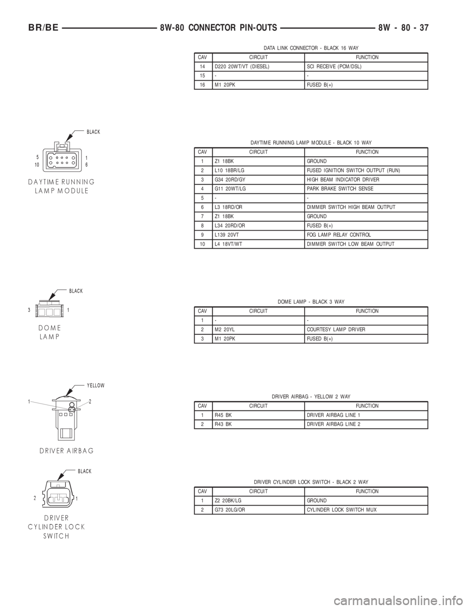
DATA LINK CONNECTOR - BLACK 16 WAY
CAV CIRCUIT FUNCTION
14 D220 20WT/VT (DIESEL) SCI RECEIVE (PCM/DSL)
15 - -
16 M1 20PK FUSED B(+)
DAYTIME RUNNING LAMP MODULE - BLACK 10 WAY
CAV CIRCUIT FUNCTION
1 Z1 18BK GROUND
2 L10 18BR/LG FUSED IGNITION SWITCH OUTPUT (RUN)
3 G34 20RD/GY HIGH BEAM INDICATOR DRIVER
4 G11 20WT/LG PARK BRAKE SWITCH SENSE
5- -
6 L3 18RD/OR DIMMER SWITCH HIGH BEAM OUTPUT
7 Z1 18BK GROUND
8 L34 20RD/OR FUSED B(+)
9 L139 20VT FOG LAMP RELAY CONTROL
10 L4 18VT/WT DIMMER SWITCH LOW BEAM OUTPUT
DOME LAMP - BLACK 3 WAY
CAV CIRCUIT FUNCTION
1- -
2 M2 20YL COURTESY LAMP DRIVER
3 M1 20PK FUSED B(+)
DRIVER AIRBAG - YELLOW 2 WAY
CAV CIRCUIT FUNCTION
1 R45 BK DRIVER AIRBAG LINE 1
2 R43 BK DRIVER AIRBAG LINE 2
DRIVER CYLINDER LOCK SWITCH - BLACK 2 WAY
CAV CIRCUIT FUNCTION
1 Z2 20BK/LG GROUND
2 G73 20LG/OR CYLINDER LOCK SWITCH MUX
BR/BE8W-80 CONNECTOR PIN-OUTS 8W - 80 - 37
Page 1302 of 2255
(4) Connect the 0-414 kPa (0-60 psi) fuel pressure
test gauge (from Gauge Set 5069) to the test port on
the appropriate Adaptor Tool.The DRBtIII Scan
Tool along with the PEP module, the 500 psi
pressure transducer, and the transducer-to-test
port adapter may also be used in place of the
fuel pressure gauge.
The fittings on both tools must be in good
condition and free from any small leaks before
performing the proceeding test.
(5) Start engine and bring to normal operating
temperature.
(6) Observe test gauge. Normal operating pressure
should be 339 kPa +/±34 kPa (49.2 psi +/±5 psi).
(7) Shut engine off.
(8) Pressure should not fall below30 psi for five
minutes.
(9) If pressure falls below 30 psi, it must be deter-
mined if a fuel injector, the check valve within the
fuel pump module, or a fuel tube/line is leaking.
(10) Again, start engine and bring to normal oper-
ating temperature.
(11) Shut engine off.
(12)Testing for fuel injector or fuel rail leak-
age:Clamp off the rubber hose portion of Adaptor
Tool between the fuel rail and the test port ªTº on
Adapter Tool. If pressure now holds at or above 30
psi, a fuel injector or the fuel rail is leaking.
(13)Testing for fuel pump check valve, filter/
regulator check valve or fuel tube/line leakage:
Clamp off the rubber hose portion of Adaptor Tool
between the vehicle fuel line and test port ªTº on
Adapter Tool. If pressure now holds at or above 30
psi, a leak may be found at a fuel tube/line. If no
leaks are found at fuel tubes or lines, one of the
check valves in either the electric fuel pump or filter/
regulator may be leaking.
Note: A quick loss of pressure usually indicates a
defective check valve in the filter/regulator. A slow
loss of pressure usually indicates a defective check
valve in the electric fuel pump.
The electric fuel pump is not serviced separately.
Replace the fuel pump module assembly. The filter/
regulator may be replaced separately on certain
applications. Refer to Fuel Filter/Fuel Pressure Reg-
ulator Removal/Installation for additional informa-
tion.
STANDARD PROCEDURE - FUEL SYSTEM
PRESSURE RELEASE
Use following procedure if the fuel injector
rail is, or is not equipped with a fuel pressure
test port.
(1) Remove fuel fill cap.(2) Remove fuel pump relay from Power Distribu-
tion Center (PDC). For location of relay, refer to label
on underside of PDC cover.
(3) Start and run engine until it stalls.
(4) Attempt restarting engine until it will no
longer run.
(5) Turn ignition key to OFF position.
CAUTION: Steps 1, 2, 3 and 4 must be performed to
relieve high pressure fuel from within fuel rail. Do
not attempt to use following steps to relieve this
pressure as excessive fuel will be forced into a cyl-
inder chamber.
(6) Unplug connector from any fuel injector.
(7) Attach one end of a jumper wire with alligator
clips (18 gauge or smaller) to either injector terminal.
(8) Connect other end of jumper wire to positive
side of battery.
(9) Connect one end of a second jumper wire to
remaining injector terminal.
CAUTION: Powering an injector for more than a few
seconds will permanently damage the injector.
(10) Momentarily touch other end of jumper wire
to negative terminal of battery for no more than a
few seconds.
(11) Place a rag or towel below fuel line quick-con-
nect fitting at fuel rail.
(12) Disconnect quick-connect fitting at fuel rail.
Refer to Quick-Connect Fittings.
(13) Return fuel pump relay to PDC.
(14) One or more Diagnostic Trouble Codes (DTC's)
may have been stored in PCM memory due to fuel
pump relay removal. The DRBtscan tool must be
used to erase a DTC.
SPECIFICATIONS
SPECIFICATIONS - FUEL SYSTEM PRESSURE -
GAS ENGINES
All Gasoline Powered Engines:339 kPa 34
kPa (49.2 psi 5 psi)
BR/BEFUEL DELIVERY - GASOLINE 14 - 3
FUEL DELIVERY - GASOLINE (Continued)
Page 1304 of 2255
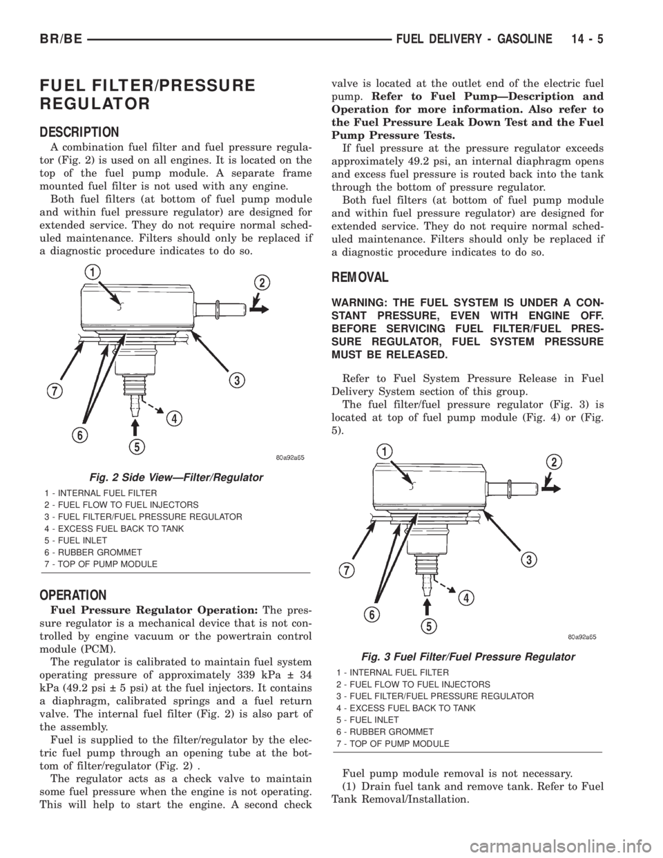
FUEL FILTER/PRESSURE
REGULATOR
DESCRIPTION
A combination fuel filter and fuel pressure regula-
tor (Fig. 2) is used on all engines. It is located on the
top of the fuel pump module. A separate frame
mounted fuel filter is not used with any engine.
Both fuel filters (at bottom of fuel pump module
and within fuel pressure regulator) are designed for
extended service. They do not require normal sched-
uled maintenance. Filters should only be replaced if
a diagnostic procedure indicates to do so.
OPERATION
Fuel Pressure Regulator Operation:The pres-
sure regulator is a mechanical device that is not con-
trolled by engine vacuum or the powertrain control
module (PCM).
The regulator is calibrated to maintain fuel system
operating pressure of approximately 339 kPa 34
kPa (49.2 psi 5 psi) at the fuel injectors. It contains
a diaphragm, calibrated springs and a fuel return
valve. The internal fuel filter (Fig. 2) is also part of
the assembly.
Fuel is supplied to the filter/regulator by the elec-
tric fuel pump through an opening tube at the bot-
tom of filter/regulator (Fig. 2) .
The regulator acts as a check valve to maintain
some fuel pressure when the engine is not operating.
This will help to start the engine. A second checkvalve is located at the outlet end of the electric fuel
pump.Refer to Fuel PumpÐDescription and
Operation for more information. Also refer to
the Fuel Pressure Leak Down Test and the Fuel
Pump Pressure Tests.
If fuel pressure at the pressure regulator exceeds
approximately 49.2 psi, an internal diaphragm opens
and excess fuel pressure is routed back into the tank
through the bottom of pressure regulator.
Both fuel filters (at bottom of fuel pump module
and within fuel pressure regulator) are designed for
extended service. They do not require normal sched-
uled maintenance. Filters should only be replaced if
a diagnostic procedure indicates to do so.
REMOVAL
WARNING: THE FUEL SYSTEM IS UNDER A CON-
STANT PRESSURE, EVEN WITH ENGINE OFF.
BEFORE SERVICING FUEL FILTER/FUEL PRES-
SURE REGULATOR, FUEL SYSTEM PRESSURE
MUST BE RELEASED.
Refer to Fuel System Pressure Release in Fuel
Delivery System section of this group.
The fuel filter/fuel pressure regulator (Fig. 3) is
located at top of fuel pump module (Fig. 4) or (Fig.
5).
Fuel pump module removal is not necessary.
(1) Drain fuel tank and remove tank. Refer to Fuel
Tank Removal/Installation.
Fig. 2 Side ViewÐFilter/Regulator
1 - INTERNAL FUEL FILTER
2 - FUEL FLOW TO FUEL INJECTORS
3 - FUEL FILTER/FUEL PRESSURE REGULATOR
4 - EXCESS FUEL BACK TO TANK
5 - FUEL INLET
6 - RUBBER GROMMET
7 - TOP OF PUMP MODULE
Fig. 3 Fuel Filter/Fuel Pressure Regulator
1 - INTERNAL FUEL FILTER
2 - FUEL FLOW TO FUEL INJECTORS
3 - FUEL FILTER/FUEL PRESSURE REGULATOR
4 - EXCESS FUEL BACK TO TANK
5 - FUEL INLET
6 - RUBBER GROMMET
7 - TOP OF PUMP MODULE
BR/BEFUEL DELIVERY - GASOLINE 14 - 5