PCM DODGE RAM 2002 Service Workshop Manual
[x] Cancel search | Manufacturer: DODGE, Model Year: 2002, Model line: RAM, Model: DODGE RAM 2002Pages: 2255, PDF Size: 62.07 MB
Page 509 of 2255
illumination lighting with the exterior lamps turned
On, the white graphics appear blue-green, while the
red graphics still appear red. The orange gauge nee-
dle is internally illuminated. Gauge illumination is
provided by replaceable incandescent bulb and bulb
holder units located on the instrument cluster elec-
tronic circuit board. The speedometer is serviced as a
unit with the instrument cluster.
OPERATION
The speedometer gives an indication to the vehicle
operator of the vehicle road speed. This gauge is con-
trolled by the instrument cluster circuit board based
upon the cluster programming and electronic mes-
sages received by the cluster from the Powertrain
Control Module (PCM) over the Chrysler Collision
Detection (CCD) data bus. The speedometer is an air
core magnetic unit that receives battery current on
the instrument cluster electronic circuit board
through the fused ignition switch output (st-run) cir-
cuit whenever the ignition switch is in the On or
Start positions. The cluster is programmed to move
the gauge needle back to the low end of the scale
after the ignition switch is turned to the Off position.
The instrument cluster circuitry controls the gauge
needle position and provides the following features:
²Message Failure- If the cluster fails to receive
a speedometer message, it will hold the gauge needle
at the last indication for about four seconds, or until
the ignition switch is turned to the Off position,
whichever occurs first. If a new speedometer message
is not received after about four seconds, the gauge
needle will return to the far left (low) end of the
scale.
²Actuator Test- Each time the cluster is put
through the actuator test, the gauge needle will be
swept to several calibration points on the gauge scale
in a prescribed sequence in order to confirm the func-
tionality of the gauge and the cluster control cir-
cuitry.
The PCM continually monitors the vehicle speed
sensor to determine the vehicle road speed, then
sends the proper vehicle speed messages to the
instrument cluster. For further diagnosis of the
speedometer or the instrument cluster circuitry that
controls the gauge, (Refer to 8 - ELECTRICAL/IN-
STRUMENT CLUSTER - DIAGNOSIS AND TEST-
ING). For proper diagnosis of the vehicle speed
sensor, the PCM, the CCD data bus, or the message
inputs to the instrument cluster that control the
speedometer, a DRBIIItscan tool is required. Refer
to the appropriate diagnostic information.
TACHOMETER
DESCRIPTION
A tachometer is standard equipment on all instru-
ment clusters. The tachometer is located just to the
left of the speedometer near the center of the instru-
ment cluster. The tachometer consists of a movable
gauge needle or pointer controlled by the instrument
cluster circuitry and a fixed 210 degree scale on the
gauge dial face that reads left-to-right either from 0
to 6 for gasoline engines, or from 0 to 4 for diesel
engines. The text ªRPM X 1000º imprinted on the
cluster overlay directly below the hub of the tachom-
eter needle identifies that each number on the
tachometer scale is to be multiplied times 1000 rpm.
The gauge scale of the gasoline engine tachometer is
red lined at 5000 rpm, while the diesel engine
tachometer is red lined at 3375 rpm. The diesel
engine tachometer also includes text that specifies
ªDIESEL FUEL ONLYº located just above the hub of
the tachometer needle. The tachometer graphics are
white and red against a black field, making them
clearly visible within the instrument cluster in day-
light. When illuminated from behind by the panel
lamps dimmer controlled cluster illumination lighting
with the exterior lamps turned On, the white graph-
ics appear blue-green, while the red graphics still
appear red. The orange gauge needle is internally
illuminated. Gauge illumination is provided by
replaceable incandescent bulb and bulb holder units
located on the instrument cluster electronic circuit
board. The tachometer is serviced as a unit with the
instrument cluster.
OPERATION
The tachometer gives an indication to the vehicle
operator of the engine speed. This gauge is controlled
by the instrument cluster circuit board based upon
the cluster programming and electronic messages
received by the cluster from the Powertrain Control
Module (PCM) over the Chrysler Collision Detection
(CCD) data bus. The tachometer is an air core mag-
netic unit that receives battery current on the instru-
ment cluster electronic circuit board through the
fused ignition switch output (st-run) circuit whenever
the ignition switch is in the On or Start positions.
The cluster is programmed to move the gauge needle
back to the low end of the scale after the ignition
switch is turned to the Off position. The instrument
cluster circuitry controls the gauge needle position
and provides the following features:
²Message Failure- If the cluster fails to receive
an engine speed message, it will hold the gauge nee-
dle at the last indication for about four seconds, or
until the ignition switch is turned to the Off position,
whichever occurs first. If a new engine speed mes-
8J - 30 INSTRUMENT CLUSTERBR/BE
SPEEDOMETER (Continued)
Page 510 of 2255
sage is not received after about four seconds, the
gauge needle will return to the far left (low) end of
the scale.
²Actuator Test- Each time the cluster is put
through the actuator test, the gauge needle will be
swept to several calibration points on the gauge scale
in a prescribed sequence in order to confirm the func-
tionality of the gauge and the cluster control cir-
cuitry.
The PCM continually monitors the crankshaft posi-
tion sensor to determine the engine speed, then
sends the proper engine speed messages to the
instrument cluster. For further diagnosis of the
tachometer or the instrument cluster circuitry that
controls the gauge, (Refer to 8 - ELECTRICAL/IN-
STRUMENT CLUSTER - DIAGNOSIS AND TEST-
ING). For proper diagnosis of the crankshaft position
sensor, the PCM, the CCD data bus, or the message
inputs to the instrument cluster that control the
tachometer, a DRBIIItscan tool is required. Refer to
the appropriate diagnostic information.
TRANS OVERTEMP
INDICATOR
DESCRIPTION
A transmission over-temperature indicator lamp is
standard equipment on all instrument clusters. How-
ever, on vehicles not equipped with the optional auto-
matic transmission, this indicator is electronically
disabled. The transmission over-temperature indica-
tor is located near the lower edge of the instrument
cluster overlay, to the left of center. The transmission
over-temperature indicator consists of a stencilled
cutout of the words ªTRANS TEMPº in the opaque
layer of the instrument cluster overlay. The dark
outer layer of the overlay prevents the indicator from
being clearly visible when it is not illuminated. A red
lens behind the cutout in the opaque layer of the
overlay causes the ªTRANS TEMPº text to appear in
red through the translucent outer layer of the over-
lay when the indicator is illuminated from behind by
a Light Emitting Diode (LED) soldered onto the
instrument cluster electronic circuit board. The
transmission over-temperature indicator is serviced
as a unit with the instrument cluster.
OPERATION
The transmission over-temperature indicator gives
an indication to the vehicle operator when the trans-
mission fluid temperature is excessive, which may
lead to accelerated transmission component wear or
failure. This indicator is controlled by a transistor on
the instrument cluster circuit board based upon the
cluster programming and electronic messagesreceived by the cluster from the Powertrain Control
Module (PCM) over the Chrysler Collision Detection
(CCD) data bus. The transmission over-temperature
indicator Light Emitting Diode (LED) receives bat-
tery current on the instrument cluster electronic cir-
cuit board through the fused ignition switch output
(st-run) circuit whenever the ignition switch is in the
On or Start positions; therefore, the LED will always
be off when the ignition switch is in any position
except On or Start. The LED only illuminates when
it is provided a path to ground by the instrument
cluster transistor. The instrument cluster will turn
on the transmission over-temperature indicator for
the following reasons:
²Bulb Test- Each time the ignition switch is
turned to the On position the transmission over-tem-
perature indicator is illuminated for about two sec-
onds as a bulb test.
²Trans Over-Temp Lamp-On Message- Each
time the cluster receives a trans over-temp lamp-on
message from the PCM indicating that the transmis-
sion fluid temperature is 135É C (275É F) or higher,
the indicator will be illuminated and a single chime
tone is sounded. The lamp remains illuminated until
the cluster receives a trans over-temp lamp-off mes-
sage from the PCM, or until the ignition switch is
turned to the Off position, whichever occurs first.
The chime tone feature will only repeat during the
same ignition cycle if the transmission over-tempera-
ture indicator is cycled off and then on again by the
appropriate trans over-temp messages from the PCM.
²Actuator Test- Each time the cluster is put
through the actuator test, the indicator will be
turned on during the bulb check portion of the test to
confirm the functionality of the LED and the cluster
control circuitry.
The PCM continually monitors the transmission
temperature sensor to determine the transmission
operating condition, then sends the proper messages
to the instrument cluster. If the instrument cluster
turns on the transmission over-temperature indicator
due to a high transmission oil temperature condition,
it may indicate that the transmission and/or the
transmission cooling system are being overloaded or
that they require service. For further diagnosis of the
transmission over-temperature indicator or the
instrument cluster circuitry that controls the LED,
(Refer to 8 - ELECTRICAL/INSTRUMENT CLUS-
TER - DIAGNOSIS AND TESTING). For proper
diagnosis of the transmission temperature sensor, the
PCM, the CCD data bus, or the message inputs to
the instrument cluster that control the transmission
over-temperature indicator, a DRBIIItscan tool is
required. Refer to the appropriate diagnostic infor-
mation.
BR/BEINSTRUMENT CLUSTER 8J - 31
TACHOMETER (Continued)
Page 512 of 2255
OPERATION
The upshift indicator gives an indication to the
vehicle operator when the transmission should be
shifted to the next highest gear in order to achieve
the best fuel economy. This indicator is controlled by
a transistor on the instrument cluster circuit board
based upon the cluster programming and electronic
messages received by the cluster from the Powertrain
Control Module (PCM) over the Chrysler Collision
Detection (CCD) data bus. The upshift indicator bulb
receives battery current on the instrument cluster
electronic circuit board through the fused ignition
switch output (st-run) circuit whenever the ignition
switch is in the On or Start positions; therefore, the
lamp will always be off when the ignition switch is in
any position except On or Start. The bulb only illu-
minates when it is provided a path to ground by the
instrument cluster transistor. On models not
equipped with a manual transmission, the incandes-
cent bulb and bulb holder unit are not installed at
the factory when the vehicle is built. The instrument
cluster will turn on the upshift indicator for the fol-
lowing reasons:
²Upshift Lamp-On Message- Each time the
cluster receives an upshift lamp-on message from the
PCM indicating the engine speed and load conditions
are right for a transmission upshift to occur, the
upshift indicator is illuminated. The indicator
remains illuminated until the cluster receives an
upshift lamp-off message from the PCM or until the
ignition switch is turned to the Off position, which-
ever occurs first. The PCM will normally send an
upshift lamp-off message three to five seconds after a
lamp-on message, if an upshift is not performed. The
indicator will then remain off until the vehicle stops
accelerating and is brought back into the range of
indicator operation, or until the transmission is
shifted into another gear.
²Actuator Test- Each time the cluster is put
through the actuator test, the indicator will be
turned on during the bulb check portion of the test to
confirm the functionality of the indicator and the
cluster control circuitry.
The PCM continually monitors the engine speed
and load conditions to determine the proper fuel and
ignition requirements. The PCM then sends the
proper messages to the instrument cluster. If the
upshift indicator fails to light during normal vehicle
operation, replace the bulb with a known good unit.
For further diagnosis of the upshift indicator or the
instrument cluster circuitry that controls the indica-
tor, (Refer to 8 - ELECTRICAL/INSTRUMENT
CLUSTER - DIAGNOSIS AND TESTING). For
proper diagnosis of the PCM, the CCD data bus, or
the message inputs to the instrument cluster that
control the upshift indicator, a DRBIIItscan tool isrequired. Refer to the appropriate diagnostic infor-
mation.
VOLTAGE GAUGE
DESCRIPTION
A voltage gauge is standard equipment on all
instrument clusters. The voltage gauge is located in
the upper left quadrant of the instrument cluster,
above the temperature gauge. The voltage gauge con-
sists of a movable gauge needle or pointer controlled
by the instrument cluster circuitry and a fixed 90
degree scale on the cluster overlay that reads left-to-
right from 8 volts to 18 volts. An International Con-
trol and Display Symbol icon for ªBattery Charging
Conditionº is located directly below the lowest grad-
uation of the gauge scale. The voltage gauge graphics
are white against a black field except for a single red
graduation at each end of the gauge scale, making
them clearly visible within the instrument cluster in
daylight. When illuminated from behind by the panel
lamps dimmer controlled cluster illumination lighting
with the exterior lamps turned On, the white graph-
ics appear blue-green and the red graphics appear
red. The orange gauge needle is internally illumi-
nated. Gauge illumination is provided by replaceable
incandescent bulb and bulb holder units located on
the instrument cluster electronic circuit board. The
voltage gauge is serviced as a unit with the instru-
ment cluster.
OPERATION
The voltage gauge gives an indication to the vehi-
cle operator of the electrical system voltage. This
gauge is controlled by the instrument cluster circuit
board based upon the cluster programming and elec-
tronic messages received by the cluster from the
Powertrain Control Module (PCM) over the Chrysler
Collision Detection (CCD) data bus. The voltage
gauge is an air core magnetic unit that receives bat-
tery current on the instrument cluster electronic cir-
cuit board through the fused ignition switch output
(st-run) circuit whenever the ignition switch is in the
On or Start positions. The cluster is programmed to
move the gauge needle back to the low end of the
scale after the ignition switch is turned to the Off
position. The instrument cluster circuitry controls
the gauge needle position and provides the following
features:
²Charge Fail Message- Each time the cluster
receives a message from the PCM indicating a charge
fail condition (system voltage is 10.8 volts or lower),
the gauge needle is moved to the 8 volt graduation
on the gauge scale and the check gauges indicator is
illuminated. The gauge needle remains on the 8 volt
BR/BEINSTRUMENT CLUSTER 8J - 33
UPSHIFT INDICATOR (Continued)
Page 513 of 2255
graduation and the check gauges indicator remains
illuminated until the cluster receives a message from
the PCM indicating there is no charge fail condition
(system voltage is 10.9 volts or higher, but lower
than 16.7 volts), or until the ignition switch is turned
to the Off position, whichever occurs first. On models
equipped with the optional diesel engine, the instru-
ment cluster is programmed to support the voltmeter
gauge needle above the low end of normal graduation
and suppress the check gauges indicator operation
until ten seconds after the engine intake manifold air
heater has completed its cycle.
²Voltage High Message- Each time the cluster
receives a message from the PCM indicating a volt-
age high condition (system voltage is 16.7 volts or
higher), the gauge needle is moved to the 18 volt
graduation on the gauge scale and the check gauges
indicator is illuminated. The gauge needle remains
on the 18 volt graduation and the check gauges indi-
cator remains illuminated until the cluster receives a
message from the PCM indicating there is no voltage
high condition (system voltage is 16.6 volts or lower,
but higher than 10.9 volts), or until the ignition
switch is turned to the Off position, whichever occurs
first.
²Message Failure- If the cluster fails to receive
a system voltage message, it will hold the gauge nee-
dle at the last indication until a new message is
received, or until the ignition switch is turned to the
Off position, whichever occurs first.
²Actuator Test- Each time the cluster is put
through the actuator test, the gauge needle will be
swept to several calibration points on the gauge scale
in a prescribed sequence in order to confirm the func-
tionality of the gauge and the cluster control cir-
cuitry.
The PCM continually monitors the system voltage
to control the generator output. The PCM then sends
the proper system voltage messages to the instru-
ment cluster. For further diagnosis of the voltage
gauge or the instrument cluster circuitry that con-
trols the gauge, (Refer to 8 - ELECTRICAL/INSTRU-
MENT CLUSTER - DIAGNOSIS AND TESTING). If
the instrument cluster turns on the check gauges
indicator due to a charge fail or voltage high condi-
tion, it may indicate that the charging system
requires service. For proper diagnosis of the charging
system, the CCD data bus, or the message inputs to
the instrument cluster that control the voltage
gauge, a DRBIIItscan tool is required. Refer to the
appropriate diagnostic information.WAIT-TO-START INDICATOR
DESCRIPTION
A wait-to-start indicator is standard equipment on
all instrument clusters, but is only functional in vehi-
cles equipped with an optional diesel engine. The
wait-to-start indicator is located near the lower edge
of the instrument cluster overlay, to the right of cen-
ter. The wait-to-start indicator consists of a stenciled
cutout of the text ªWAIT TO STARTº in the opaque
layer of the cluster overlay. The dark outer layer of
the overlay prevents the indicator from being clearly
visible when it is not illuminated. A red lens located
behind the cutout causes the ªWAIT TO STARTº text
to appear in red through the translucent outer layer
of the overlay when the indicator is illuminated from
behind by a Light Emitting Diode (LED) that is sol-
dered onto the instrument cluster electronic circuit
board. The wait-to-start indicator is serviced as a
unit with the instrument cluster.
OPERATION
The wait-to-start indicator gives an indication to
the vehicle operator when the diesel engine intake
air heater is energized in its preheat operating mode.
This indicator is controlled by a hard wired input to
the instrument cluster from the Engine Control Mod-
ule (ECM). The wait-to-start indicator Light Emitting
Diode (LED) receives battery current on the instru-
ment cluster electronic circuit board through the
fused ignition switch output (st-run) circuit whenever
the ignition switch is in the On or Start positions;
therefore, the lamp will always be off when the igni-
tion switch is in any position except On or Start. The
indicator LED only illuminates when it is switched to
ground by the input from the ECM. The ECM will
turn on the wait-to-start indicator by pulling the
wait-to-start indicator driver circuit to ground each
time the ignition switch is turned to the On or Start
positions. The indicator then remains illuminated
until the ECM detects that the air within the intake
manifold is the proper temperature to ensure reliable
and efficient engine starting, until the ECM detects
that the engine is running, or until the ignition
switch is turned to the Off position, whichever occurs
first.
The ECM continually monitors the intake manifold
air temperature sensor, the Manifold Absolute Pres-
sure (MAP) sensor, and many other vehicle condi-
tions to determine when the wait-to-start indicator
should be illuminated. For proper diagnosis of the
wait-to-start indicator, the ECM, or the inputs the
ECM uses to control the wait-to-start indicator oper-
ation, a DRBIIItscan tool is required. Refer to the
appropriate diagnostic information.
8J - 34 INSTRUMENT CLUSTERBR/BE
VOLTAGE GAUGE (Continued)
Page 519 of 2255
(9) Disconnect the instrument panel wire harness
connector for the multi-function switch from the
switch connector receptacle. Check for continuity
between the hazard flasher signal circuit cavities in
the JB receptacle for the combination flasher and the
instrument panel wire harness connector for the
multi-function switch. There should be continuity. If
OK, go to Step 10. If not OK, repair the open hazard
flasher signal circuit between the JB and the multi-
function switch as required.
(10) Check for continuity between the flasher out-
put circuit cavities of the JB receptacle for the com-
bination flasher and in the instrument panel wire
harness connector for the multi-function switch.
There should be continuity. If OK, test the multi-
function switch. (Refer to 8 - ELECTRICAL/LAMPS/
LIGHTING - EXTERIOR/MULTI-FUNCTION
SWITCH - DIAGNOSIS AND TESTING). If not OK,
repair the open flasher output circuit between the JB
and the multi-function switch as required.
SPECIFICATIONS
EXTERIOR LAMPS
LAMP BULB
Back-up 3157
Cargo 921
Center High Mounted
Stop921
Clearance Roof Mounted 168
Fog Lamps 896
Headlamp - SLT 9004LL
Headlamp - Sport Low
Beam9007
Headlamp - Sport High
Beam9004LL
License Plate w/o
Bumper1155
License Plate -Step
Bumper168
Park/Turn Signal 3157NA
Snow Plow Control 161
Tail/Brake/Turn Signal 3157
Tail/Brake/Cab - Chassis 1157
Underhood 105
SPECIAL TOOLS
HEADLAMP ALIGNMENT
BRAKE LAMP SWITCH
DESCRIPTION
The plunger type brake lamp switch is mounted on
a bracket attached to the brake pedal support under
the instrument panel.
CAUTION: The switch can only be adjusted during
initial installation. If the switch is not adjusted prop-
erly a new switch must be installed.
OPERATION
The brake lamp switch is used for the brake lamp,
speed control brake sensor circuits and electronic
brake distribution (EBD). The brake lamp circuit is
open until the plunger is depressed. The speed con-
trol and brake sensor circuits are closed until the
plunger is depressed.
When the brake light switch is activated, the Pow-
ertrain Control Module (PCM) receives an input indi-
cating that the brakes are being applied. After
receiving this input, the PCM maintains idle speed to
a scheduled rpm through control of the Idle Air Con-
trol (IAC) motor. The brake switch input is also used
to disable vent and vacuum solenoid output signals
to the speed control servo.
Vehicles equipped with the speed control option use
a dual function brake lamp switch. The PCM moni-
tors the state of the dual function brake lamp switch.
Refer to the Brake section for more information on
brake lamp switch service and adjustment proce-
dures.
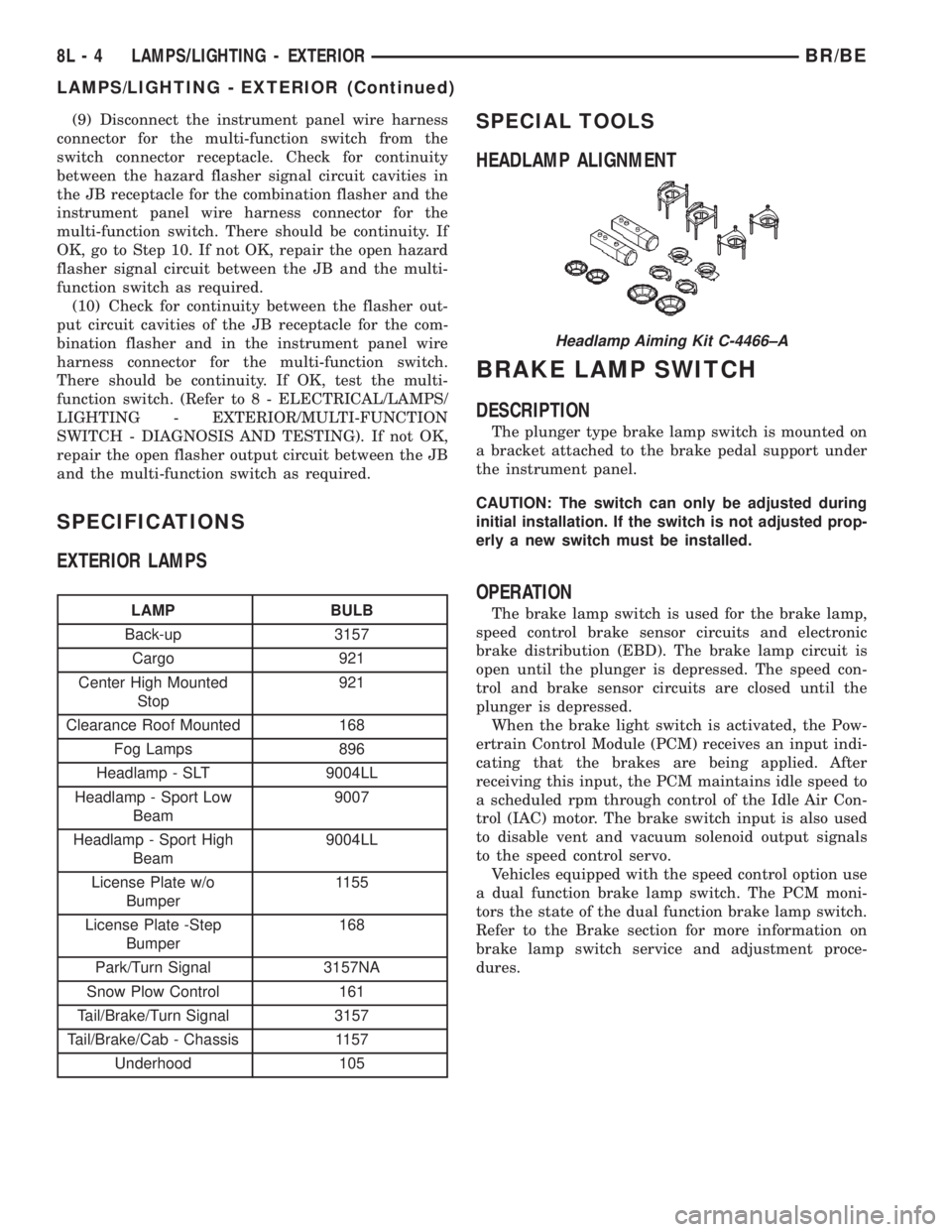
Headlamp Aiming Kit C-4466±A
8L - 4 LAMPS/LIGHTING - EXTERIORBR/BE
LAMPS/LIGHTING - EXTERIOR (Continued)
Page 520 of 2255
The brake switch is equipped with three sets of
contacts, one normally open and the other two nor-
mally closed (brakes disengaged). The PCM sends a
12 volt signal to one of the normally closed contacts
in the brake switch, which is returned to the PCM as
a brake switch state signal. With the contacts closed,
the 12 volt signal is pulled to ground causing the sig-
nal to go low. The low voltage signal, monitored by
the PCM, indicates that the brakes are not applied.
When the brakes are applied, the contacts open,
causing the PCM's output brake signal to go high,
disengaging the speed control, cutting off PCM power
to the speed control solenoids.
The second set of normally closed contacts supplies
12 volts from the PCM any time speed control is
turned on. Through the brake switch, current is
routed to the speed control servo solenoids. The
speed control solenoids (vacuum, vent and dump) are
provided this current any time the speed control is
ON and the brakes are disengaged.
When the driver applies the brakes, the contacts
open and current is interrupted to the solenoids. The
normally open contacts are fed battery voltage. When
the brakes are applied, battery voltage is supplied to
the brake lamps.
DIAGNOSIS AND TESTING - BRAKE LAMP
SWITCH
The brake lamp switch can be tested with an ohm-
meter. The ohmmeter is used to check continuity
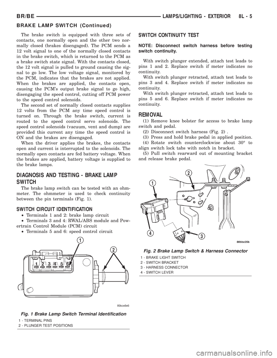
between the pin terminals (Fig. 1).
SWITCH CIRCUIT IDENTIFICATION
²Terminals 1 and 2: brake lamp circuit
²Terminals 3 and 4: RWAL/ABS module and Pow-
ertrain Control Module (PCM) circuit
²Terminals 5 and 6: speed control circuit
SWITCH CONTINUITY TEST
NOTE: Disconnect switch harness before testing
switch continuity.
With switch plunger extended, attach test leads to
pins 1 and 2. Replace switch if meter indicates no
continuity.
With switch plunger retracted, attach test leads to
pins 3 and 4. Replace switch if meter indicates no
continuity.
With switch plunger retracted, attach test leads to
pins 5 and 6. Replace switch if meter indicates no
continuity.
REMOVAL
(1) Remove knee bolster for access to brake lamp
switch and pedal.
(2) Disconnect switch harness (Fig. 2) .
(3) Press and hold brake pedal in applied position.
(4) Rotate switch counterclockwise about 30É to
align switch lock tabs with notch in bracket.
(5) Pull switch rearward out of mounting bracket
and release brake pedal.
Fig. 1 Brake Lamp Switch Terminal Identification
1 - TERMINAL PINS
2 - PLUNGER TEST POSITIONS
Fig. 2 Brake Lamp Switch & Harness Connector
1 - BRAKE LIGHT SWITCH
2 - SWITCH BRACKET
3 - HARNESS CONNECTOR
4 - SWITCH LEVER
BR/BELAMPS/LIGHTING - EXTERIOR 8L - 5
BRAKE LAMP SWITCH (Continued)
Page 570 of 2255
optional horn chirp durations (twenty or forty milli-
seconds) can also be selected.
²Illuminated Entry- This feature turns on the
courtesy lamps in the vehicle for a timed interval
(about thirty seconds) each time a valid Unlock sig-
nal has been received from the RKE transmitter.
²Panic Mode- This feature allows the vehicle
operator to cause the vehicle horn to pulse, the head-
lights to flash, and the courtesy lamps to illuminate
for about three minutes by depressing a Panic button
on the RKE transmitter. Pressing the Panic button a
second time will cancel the Panic mode. A vehicle
speed of about 24 kilometers-per-hour (15 miles-per-
hour) will also cancel the panic mode.
OPERATION
OPERATION - POWER LOCKS
All versions of the power lock system allow both
doors to be locked or unlocked electrically by operat-
ing the power lock switch on either front door trim
panel. On vehicles that are also equipped with the
optional Remote Keyless Entry (RKE) system, both
doors may also be locked or unlocked using a key in
either front door lock cylinder, or by using the RKE
transmitter. On vehicles with the RKE system, if cer-
tain features have been electronically enabled, the
locks may also be operated automatically by the
high-line or premium Central Timer Module (CTM)
based upon various other inputs. Those features and
their inputs are:
²Automatic Door Lock- If enabled, the high-
line/premium CTM will automatically lock the doors
when it receives a message from the Powertrain Con-
trol Module (PCM) indicating that the vehicle speed
is about 24 kilometers-per-hour (15 miles-per-hour)
or greater. The CTM also monitors the door ajar
switches, and will not activate the automatic door
lock feature until both doors have been closed for at
least five seconds. If this feature is enabled and a
door is opened after the vehicle is moving, the CTM
will also lock the doors five seconds after both doors
are closed.
²Central Locking- Vehicles equipped with a
high-line/premium CTM also have a resistor-multi-
plexed door cylinder lock switch mounted to the back
of the door lock cylinder within each front door. The
CTM continually monitors the input from these
switches to provide the central locking/unlocking fea-
ture. The CTM will automatically lock or unlock both
front doors when either front door is locked or
unlocked using a key.
²Door Lock Inhibit- The high-line/premium
CTM receives inputs from the key-in ignition switch,the headlamp switch, and the door ajar switches. The
logic within the CTM allows it to monitor these
inputs to provide a door lock inhibit feature. The
door lock inhibit feature prevents the power lock sys-
tem from being energized with a power lock switch
input if the driver door is open with the headlamps
on or the key still in the ignition switch. However,
the locks can still be operated with the manual door
lock button or with a key in the door lock cylinder,
and the power locks will still operate using the RKE
transmitter while the driver door is open with the
headlamps on or a key in the ignition.
²Enhanced Accident Response- If enabled,
the high-line/premium CTM provides an enhanced
accident response feature. This feature uses elec-
tronic message inputs received by the CTM from the
Airbag Control Module (ACM) to determine when an
airbag has been deployed. The CTM also monitors
the state of the power lock system and the vehicle
speed messages from the PCM in order to provide
this feature. If the airbag has been deployed and the
vehicle has stopped moving, the CTM will automati-
cally unlock the doors, prevent the doors from being
locked, and turn on the courtesy lamps inside the
vehicle. Of course, these responses are dependent
upon a functional battery and electrical circuitry fol-
lowing the impact.
All versions of the power lock system operate on
battery current received through a fused B(+) circuit
from a fuse in the Junction Block (JB) so that the
system remains functional, regardless of the ignition
switch position. Also, in both versions of the power
lock system, each power lock switch receives battery
current independent of the other. In vehicles with the
base version of the power lock system, the driver side
power lock switch receives ground through the body
wire harness. A single wire take out of the body wire
harness with an eyelet terminal connector is secured
by a ground screw to the lower left B-pillar (regular
cab, extended cab) or lower left quarter inner panel
(quad cab). The passenger side power lock switch
receives ground through the driver side power lock
switch in the base version of the power lock system.
The base version power lock switches direct the
appropriate battery current and ground feeds to the
power lock motors. In the power lock system for vehi-
cles with the RKE system, the power lock switches
direct a battery current Lock or Unlock request sig-
nal to the high-line or premium CTM, and the CTM
energizes internal relays to direct the appropriate
battery current and ground feeds to the power lock
motors.
BR/BEPOWER LOCKS 8N - 3
POWER LOCKS (Continued)
Page 571 of 2255
OPERATION - REMOTE KEYLESS ENTRY
SYSTEM
On vehicles with the Remote Keyless Entry (RKE)
system, the power locks can be operated remotely
using the RKE transmitter. If the vehicle is so
equipped, the RKE transmitter also arms and dis-
arms the factory-installed Vehicle Theft Security Sys-
tem (VTSS). Three small, recessed buttons on the
outside of the transmitter case labelled Lock, Unlock,
and Panic allow the user to choose the function that
is desired. The RKE transmitter then sends the
appropriate Radio Frequency (RF) signal. An RF
receiver that is integral to the high-line or premium
version of the Central Timer Module (CTM) receives
the transmitted signal, then uses its internal elec-
tronic programming to determine whether the
received signal is valid and what function has been
requested. If the signal is valid, the CTM provides
the programmed features.
Besides operating the power lock system and arm-
ing or disarming the VTSS, the RKE system also
controls the following features:
²Horn Chirp- If this feature is enabled, the
CTM provides a horn chirp by internally pulling the
control coil of the horn relay to ground through a
hard wired circuit output.
²Illuminated Entry- The CTM provides illumi-
nated entry by internally controlling the current flow
to the courtesy lamps in the vehicle through a hard
wired output circuit.
²Panic Mode- The CTM provides the horn pulse
and headlight flash by internally pulling the control
coils of the horn relay and headlamp relay to ground
through hard wired circuit outputs. The CTM con-
trols the current flow to the courtesy lamps in the
vehicle through a hard wired output circuit. The
CTM also monitors the vehicle speed through elec-
tronic messages it receives from the Powertrain Con-
trol Module (PCM) over the Chrysler Collision
Detection (CCD) data bus network.
The RKE system operates on battery current
received through a fused B(+) circuit from a fuse in
the Junction Block (JB) so that the system remains
functional, regardless of the ignition switch position.
The RKE system can retain the vehicle access codes
of up to four RKE transmitters. The transmitter
codes are retained in RKE system memory, even if
the battery is disconnected. If a transmitter is faulty
or is lost, new transmitter vehicle access codes can be
programmed into the system using a DRBIIItscan
tool. Refer to the appropriate diagnostic information.
Many of the electronic features in the vehicle con-
trolled or supported by the high-line or premium ver-
sions of the CTM are programmable using the
DRBIIItscan tool. In addition, the high-line/pre-
mium CTM software is Flash compatible, whichmeans it can be reprogrammed using Flash repro-
gramming procedures. However, if any of the CTM
hardware components are damaged or faulty, the
entire CTM unit must be replaced. The hard wired
inputs or outputs of the CTM can be diagnosed using
conventional diagnostic tools and methods; however,
for diagnosis of the high-line or premium versions of
the CTM or the CCD data bus, the use of a DRBIIIt
scan tool is required. Refer to the appropriate diag-
nostic information.
DIAGNOSIS AND TESTING
DIAGNOSIS AND TESTING - POWER LOCKS
The following tests provide a preliminary diagnosis
for the power lock system usedonlyon vehicles
equipped with a base version of the Central Timer
Module (CTM). These testsdo notapply to the diag-
nosis of the power lock system used on vehicles
equipped with the optional Remote Keyless Entry
(RKE) system, which includes a high-line or premium
CTM. (Refer to 8 - ELECTRICAL/POWER LOCKS -
DIAGNOSIS AND TESTING - POWER LOCK &
REMOTE KEYLESS ENTRY SYSTEM). Refer to the
appropriate wiring information. The wiring informa-
tion includes wiring diagrams, proper wire and con-
nector repair procedures, details of wire harness
routing and retention, connector pin-out information
and location views for the various wire harness con-
nectors, splices and grounds.
PRELIMINARY TESTS
To begin this test, note the system operation while
you actuate both the Lock and Unlock functions with
the power lock switches. Then, proceed as follows:
²If the entire power lock system fails to function
with both of the power lock switches, check the fused
B(+) fuse in the Junction Block (JB). If the fuse is
OK, check the ground circuit between the driver side
power lock switch and ground (G301). If the ground
circuit is OK, proceed to the diagnosis of the power
lock motors. (Refer to 8 - ELECTRICAL/POWER
LOCKS/POWER LOCK MOTOR - DIAGNOSIS AND
TESTING).
²If the entire power lock system fails to function
with only one of the power lock switches, proceed to
diagnosis of the power lock switches. (Refer to 8 -
ELECTRICAL/POWER LOCKS/POWER LOCK
SWITCH - DIAGNOSIS AND TESTING).
²If only one power lock motor fails to operate
with both power lock switches, proceed to diagnosis
of the power lock motor. (Refer to 8 - ELECTRICAL/
POWER LOCKS/POWER LOCK MOTOR - DIAGNO-
SIS AND TESTING).
8N - 4 POWER LOCKSBR/BE
POWER LOCKS (Continued)
Page 624 of 2255
SPEED CONTROL
TABLE OF CONTENTS
page page
SPEED CONTROL
DESCRIPTION
DESCRIPTION - SPEED CONTROL SYSTEM . 1
DESCRIPTION - VEHICLE SPEED INPUT....2
OPERATION - SPEED CONTROL SYSTEM....2
DIAGNOSIS AND TESTING
DIAGNOSIS AND TESTING - VACUUM
SUPPLY TEST.........................3
DIAGNOSIS AND TESTING - ROAD TEST....4
SPECIFICATIONS
TORQUE - SPEED CONTROL SYSTEM.....4
CABLE
DESCRIPTION..........................4
OPERATION............................4
REMOVAL
REMOVAL - GAS ENGINES...............4
REMOVAL - DIESEL WITH AUTO. TRANS. . . . 5
INSTALLATION
INSTALLATION - GAS ENGINES...........5
INSTALLATION - DIESEL WITH AUTO.
TRANS...............................6SPEED CONTROL SERVO
DESCRIPTION..........................6
OPERATION............................6
REMOVAL
REMOVAL............................6
REMOVAL - DIESEL WITH AUTO. TRANS. . . . 9
INSTALLATION
INSTALLATION.......................11
INSTALLATION - DIESEL WITH AUTO.
TRANS..............................12
SWITCH
DESCRIPTION.........................12
OPERATION...........................12
REMOVAL.............................13
INSTALLATION.........................14
VACUUM RESERVOIR
DESCRIPTION.........................14
REMOVAL.............................14
INSTALLATION.........................15
SPEED CONTROL
DESCRIPTION
DESCRIPTION - SPEED CONTROL SYSTEM
Gas Engines and/or Diesel With Automatic Trans.
The speed control system is operated by the use of
a cable and a vacuum controlled servo. Electronic
control of the speed control system is integrated into
the Powertrain Control Module (PCM). The controls
consist of two steering wheel mounted switches. The
switches are labeled: ON/OFF, RES/ACCEL, SET,
COAST, and CANCEL.
The system is designed to operate at speeds above
30 mph (50 km/h).
WARNING: THE USE OF SPEED CONTROL IS NOT
RECOMMENDED WHEN DRIVING CONDITIONS DO
NOT PERMIT MAINTAINING A CONSTANT SPEED,
SUCH AS IN HEAVY TRAFFIC OR ON ROADS THATARE WINDING, ICY, SNOW COVERED, OR SLIP-
PERY.
Diesel With Manual Trans.
The speed control system is fully electronically con-
trolled by the Engine Control Module (ECM).A
cable and a vacuum controlled servo are not
used if the vehicle is equipped with a manual
transmission and a diesel engine. This is a ser-
vo-less system.The controls consist of two steering
wheel mounted switches. The switches are labeled:
ON/OFF, RES/ACCEL, SET, COAST, and CANCEL.
The system is designed to operate at speeds above
30 mph (50 km/h).
WARNING: THE USE OF SPEED CONTROL IS NOT
RECOMMENDED WHEN DRIVING CONDITIONS DO
NOT PERMIT MAINTAINING A CONSTANT SPEED,
SUCH AS IN HEAVY TRAFFIC OR ON ROADS THAT
ARE WINDING, ICY, SNOW COVERED, OR SLIP-
PERY.
BR/BESPEED CONTROL 8P - 1
Page 625 of 2255
DESCRIPTION - VEHICLE SPEED INPUT
Gas Engines and/or Diesel With Automatic Trans.
The Vehicle Speed Sensor (VSS) is no longer used
for any Dodge Truck.
Vehicle speed and distance covered are measured
by the Rear Wheel Speed Sensor. The sensor is
mounted to the rear axle. A signal is sent from this
sensor to the Controller Antilock Brake (CAB) com-
puter. A signal is then sent from the CAB to the Pow-
ertrain Control Module (PCM) to determine vehicle
speed and distance covered. The PCM will then
determine strategies for speed control system opera-
tion.
Diesel With Manual Trans.
The Vehicle Speed Sensor (VSS) is no longer used
for any Dodge Truck.
Vehicle speed and distance covered are measured
by the Rear Wheel Speed Sensor. The sensor is
mounted to the rear axle. A signal is sent from this
sensor to the Controller Antilock Brake (CAB) com-
puter. A signal is then sent from the CAB to the
Engine Control Module (ECM) to determine vehicle
speed and distance covered. The ECM will then
determine strategies for speed control system opera-
tion.
OPERATION - SPEED CONTROL SYSTEM
Gas Engines and/or Diesel With Automatic Trans.
When speed control is selected by depressing the
ON switch, the PCM allows a set speed to be stored
in PCM RAM for speed control. To store a set speed,
depress the SET switch while the vehicle is moving
at a speed between 35 and 85 mph. In order for the
speed control to engage, the brakes cannot be
applied, nor can the gear selector be indicating the
transmission is in Park or Neutral.
The speed control can be disengaged manually by:
²Stepping on the brake pedal.
²Depressing the OFF switch.
²Depressing the CANCEL switch.
²Depressing the clutch pedal (if equipped).
NOTE: Depressing the OFF switch or turning off the
ignition switch will erase the set speed stored in
the PCM.
For added safety, the speed control system is pro-
grammed to disengage for any of the following condi-
tions:
²An indication of Park or Neutral.
²A rapid increase of rpm (indication that the
clutch has been disengaged).²Excessive engine rpm (indicates that the trans-
mission may be in a low gear).
²The speed signal increases at a rate of 10 mph
per second (indicates that the coefficient of friction
between the road surface and tires is extremely low).
²The speed signal decreases at a rate of 10 mph
per second (indicates that the vehicle may have
decelerated at an extremely high rate).
Once the speed control has been disengaged,
depressing the RES/ACCEL switch (when speed is
greater than 30 mph) restores the vehicle to the tar-
get speed that was stored in the PCM.
While the speed control is engaged, the driver can
increase the vehicle speed by depressing the RES/AC-
CEL switch. The new target speed is stored in the
PCM when the RES/ACCEL is released. The PCM
also has a9tap-up9feature in which vehicle speed
increases at a rate of approximately 2 mph for each
momentary switch activation of the RES/ACCEL
switch.
A ªtap downº feature is used to decelerate without
disengaging the speed control system. To decelerate
from an existing recorded target speed, momentarily
depress the COAST switch. For each switch activa-
tion, speed will be lowered approximately 1 mph.
Diesel With Manual Trans.
When speed control is selected by depressing the
ON switch, the Engine Control Module (ECM) allows
a set speed to be stored in ECM RAM for speed con-
trol. To store a set speed, depress the SET switch
while the vehicle is moving at a speed between 35
and 85 mph. In order for the speed control to engage,
the brakes cannot be applied.The speed control can
be disengaged manually by:
²Stepping on the brake pedal.
²Depressing the OFF switch.
²Depressing the CANCEL switch.
²Depressing the clutch pedal.
NOTE: Depressing the OFF switch or turning off the
ignition switch will erase the set speed stored in
the ECM.
For added safety, the speed control system is pro-
grammed to disengage for any of the following condi-
tions:
²A rapid increase of rpm (indication that the
clutch has been disengaged).
²Excessive engine rpm (indicates that the trans-
mission may be in a low gear).
²The speed signal increases at a rate of 10 mph
per second (indicates that the coefficient of friction
between the road surface and tires is extremely low).
²The speed signal decreases at a rate of 10 mph
per second (indicates that the vehicle may have
decelerated at an extremely high rate).
8P - 2 SPEED CONTROLBR/BE
SPEED CONTROL (Continued)