PCM DODGE RAM 2002 Service Owner's Guide
[x] Cancel search | Manufacturer: DODGE, Model Year: 2002, Model line: RAM, Model: DODGE RAM 2002Pages: 2255, PDF Size: 62.07 MB
Page 461 of 2255
IGNITION COIL RESISTANCEÐ8.0L V-10
ENGINE
Primary Resistance: 0.53-0.65 Ohms. Test across the
primary connector. Refer to text for test procedures.
Secondary Resistance: 10.9-14.7K Ohms. Test
across the individual coil towers. Refer to text for test
procedures.
IGNITION TIMING
Ignition timing is not adjustable on any engine.
AUTOMATIC SHUT DOWN
RELAY
DESCRIPTION - PCM OUTPUT
The 5±pin, 12±volt, Automatic Shutdown (ASD)
relay is located in the Power Distribution Center
(PDC). Refer to label on PDC cover for relay location.
OPERATION
OPERATION - PCM OUTPUT
The ASD relay supplies battery voltage (12+ volts)
to the fuel injectors and ignition coil(s). With certain
emissions packages it also supplies 12±volts to the
oxygen sensor heating elements.
The ground circuit for the coil within the ASD
relay is controlled by the Powertrain Control Module
(PCM). The PCM operates the ASD relay by switch-
ing its ground circuit on and off.
The ASD relay will be shut±down, meaning the
12±volt power supply to the ASD relay will be de-ac-
tivated by the PCM if:
²the ignition key is left in the ON position. This
is if the engine has not been running for approxi-
mately 1.8 seconds.
²there is a crankshaft position sensor signal to
the PCM that is lower than pre-determined values.
OPERATION - ASD SENSE - PCM INPUT
A 12 volt signal at this input indicates to the PCM
that the ASD has been activated. The relay is used to
connect the oxygen sensor heater element, ignition
coil and fuel injectors to 12 volt + power supply.
This input is used only to sense that the ASD relay
is energized. If the Powertrain Control Module
(PCM) does not see 12 volts at this input when the
ASD should be activated, it will set a Diagnostic
Trouble Code (DTC).
DIAGNOSIS AND TESTING - ASD AND FUEL
PUMP RELAYS
The following description of operation and
tests apply only to the Automatic Shutdown
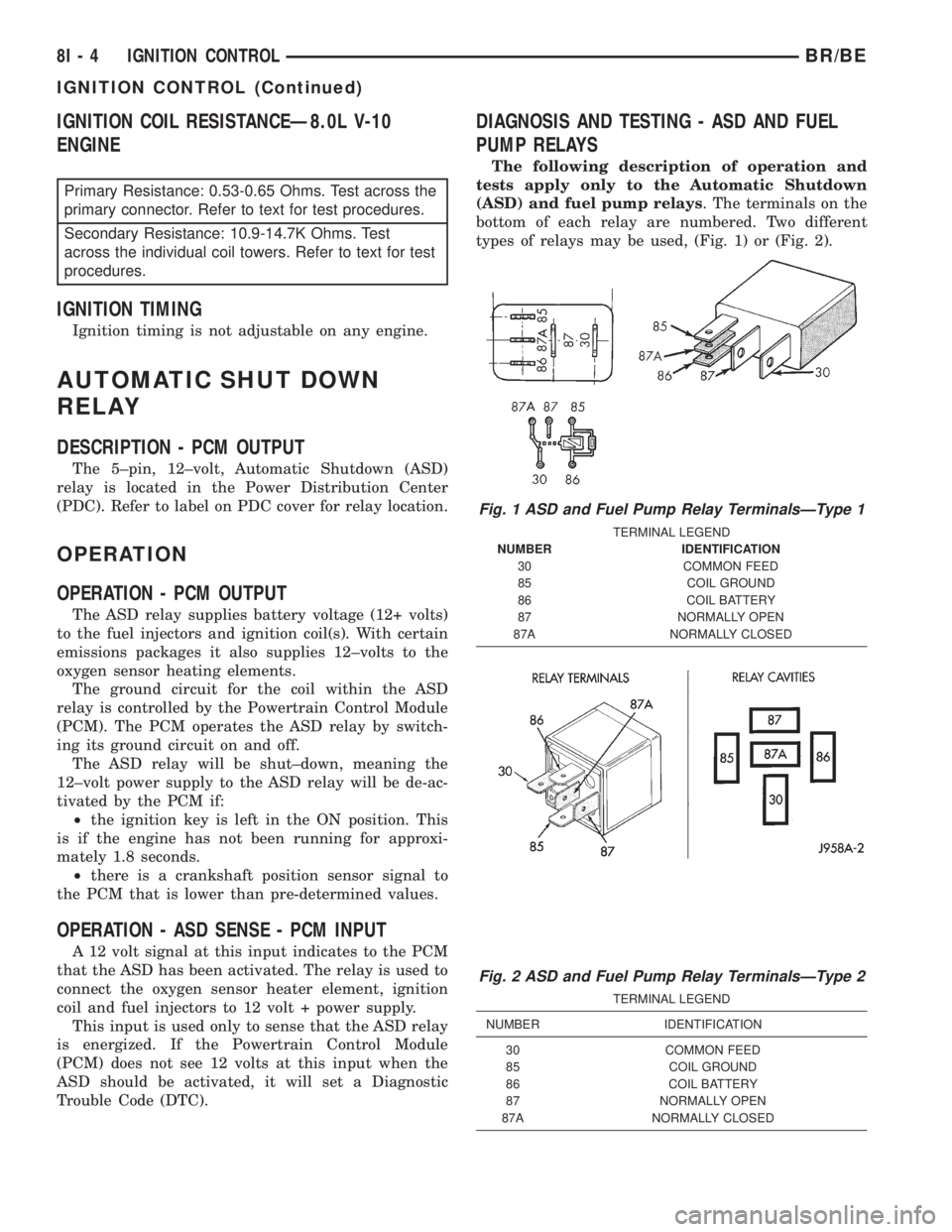
(ASD) and fuel pump relays. The terminals on the
bottom of each relay are numbered. Two different
types of relays may be used, (Fig. 1) or (Fig. 2).
Fig. 1 ASD and Fuel Pump Relay TerminalsÐType 1
TERMINAL LEGEND
NUMBER IDENTIFICATION
30 COMMON FEED
85 COIL GROUND
86 COIL BATTERY
87 NORMALLY OPEN
87A NORMALLY CLOSED
Fig. 2 ASD and Fuel Pump Relay TerminalsÐType 2
TERMINAL LEGEND
NUMBER IDENTIFICATION
30 COMMON FEED
85 COIL GROUND
86 COIL BATTERY
87 NORMALLY OPEN
87A NORMALLY CLOSED
8I - 4 IGNITION CONTROLBR/BE
IGNITION CONTROL (Continued)
Page 462 of 2255
²Terminal number 30 is connected to battery volt-
age. For both the ASD and fuel pump relays, termi-
nal 30 is connected to battery voltage at all times.
²The PCM grounds the coil side of the relay
through terminal number 85.
²Terminal number 86 supplies voltage to the coil
side of the relay.
²When the PCM de-energizes the ASD and fuel
pump relays, terminal number 87A connects to termi-
nal 30. This is the Off position. In the off position,
voltage is not supplied to the rest of the circuit. Ter-
minal 87A is the center terminal on the relay.
²When the PCM energizes the ASD and fuel
pump relays, terminal 87 connects to terminal 30.
This is the On position. Terminal 87 supplies voltage
to the rest of the circuit.
The following procedure applies to the ASD and
fuel pump relays.
(1) Remove relay from connector before testing.
(2) With the relay removed from the vehicle, use
an ohmmeter to check the resistance between termi-
nals 85 and 86. The resistance should be 75 ohms +/-
5 ohms.
(3) Connect the ohmmeter between terminals 30
and 87A. The ohmmeter should show continuity
between terminals 30 and 87A.
(4) Connect the ohmmeter between terminals 87
and 30. The ohmmeter should not show continuity at
this time.
(5) Connect one end of a jumper wire (16 gauge or
smaller) to relay terminal 85. Connect the other end
of the jumper wire to the ground side of a 12 volt
power source.
(6) Connect one end of another jumper wire (16
gauge or smaller) to the power side of the 12 volt
power source.Do not attach the other end of the
jumper wire to the relay at this time.
WARNING: DO NOT ALLOW OHMMETER TO CON-
TACT TERMINALS 85 OR 86 DURING THIS TEST.
DAMAGE TO OHMMETER MAY RESULT.
(7) Attach the other end of the jumper wire to
relay terminal 86. This activates the relay. The ohm-
meter should now show continuity between relay ter-
minals 87 and 30. The ohmmeter should not show
continuity between relay terminals 87A and 30.
(8) Disconnect jumper wires.(9) Replace the relay if it did not pass the continu-
ity and resistance tests. If the relay passed the tests,
it operates properly. Check the remainder of the ASD
and fuel pump relay circuits. Refer to 8, Wiring Dia-
grams.
REMOVAL
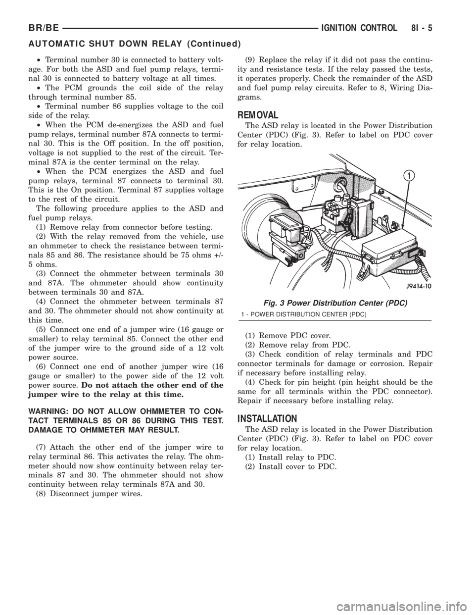
The ASD relay is located in the Power Distribution
Center (PDC) (Fig. 3). Refer to label on PDC cover
for relay location.
(1) Remove PDC cover.
(2) Remove relay from PDC.
(3) Check condition of relay terminals and PDC
connector terminals for damage or corrosion. Repair
if necessary before installing relay.
(4) Check for pin height (pin height should be the
same for all terminals within the PDC connector).
Repair if necessary before installing relay.
INSTALLATION
The ASD relay is located in the Power Distribution
Center (PDC) (Fig. 3). Refer to label on PDC cover
for relay location.
(1) Install relay to PDC.
(2) Install cover to PDC.
Fig. 3 Power Distribution Center (PDC)
1 - POWER DISTRIBUTION CENTER (PDC)
BR/BEIGNITION CONTROL 8I - 5
AUTOMATIC SHUT DOWN RELAY (Continued)
Page 464 of 2255
the ECM relating engine speed and crankshaft posi-
tion.
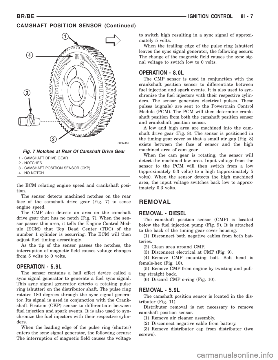
The sensor detects machined notches on the rear
face of the camshaft drive gear (Fig. 7) to sense
engine speed.
The CMP also detects an area on the camshaft
drive gear that has no notch (Fig. 7). When the sen-
sor passes this area, it tells the Engine Control Mod-
ule (ECM) that Top Dead Center (TDC) of the
number 1 cylinder is occurring. The ECM will then
adjust fuel timing accordingly.
As the tip of the sensor passes the notches, the
interruption of magnetic field causes voltage changes
from 5 volts to 0 volts.
OPERATION - 5.9L
The sensor contains a hall effect device called a
sync signal generator to generate a fuel sync signal.
This sync signal generator detects a rotating pulse
ring (shutter) on the distributor shaft. The pulse ring
rotates 180 degrees through the sync signal genera-
tor. Its signal is used in conjunction with the Crank-
shaft Position (CKP) sensor to differentiate between
fuel injection and spark events. It is also used to syn-
chronize the fuel injectors with their respective cylin-
ders.
When the leading edge of the pulse ring (shutter)
enters the sync signal generator, the following occurs:
The interruption of magnetic field causes the voltageto switch high resulting in a sync signal of approxi-
mately 5 volts.
When the trailing edge of the pulse ring (shutter)
leaves the sync signal generator, the following occurs:
The change of the magnetic field causes the sync sig-
nal voltage to switch low to 0 volts.
OPERATION - 8.0L
The CMP sensor is used in conjunction with the
crankshaft position sensor to differentiate between
fuel injection and spark events. It is also used to syn-
chronize the fuel injectors with their respective cylin-
ders. The sensor generates electrical pulses. These
pulses (signals) are sent to the Powertrain Control
Module (PCM). The PCM will then determine crank-
shaft position from both the camshaft position sensor
and crankshaft position sensor.
A low and high area are machined into the cam-
shaft drive gear (Fig. 8). The sensor is positioned in
the timing gear cover so that a small air gap (Fig. 8)
exists between the face of sensor and the high
machined area of cam gear.
When the cam gear is rotating, the sensor will
detect the machined low area. Input voltage from the
sensor to the PCM will then switch from a low
(approximately 0.3 volts) to a high (approximately 5
volts). When the sensor detects the high machined
area, the input voltage switches back low to approx-
imately 0.3 volts.
REMOVAL
REMOVAL - DIESEL
The camshaft position sensor (CMP) is located
below the fuel injection pump (Fig. 9). It is attached
to the back of the timing gear cover housing.
(1) Disconnect both negative cables from both bat-
teries.
(2) Clean area around CMP.
(3) Disconnect electrical at CMP (Fig. 9).
(4) Remove CMP mounting bolt. Bolt head is
female-hex (Fig. 10).
(5) Remove CMP from engine by twisting and pull-
ing straight back.
(6) Discard CMP o-ring (Fig. 10).
REMOVAL - 5.9L
The camshaft position sensor is located in the dis-
tributor (Fig. 11).
Distributor removal is not necessary to remove
camshaft position sensor.
(1) Remove air cleaner assembly.
(2) Disconnect negative cable from battery.
(3) Remove distributor cap from distributor (two
screws).
Fig. 7 Notches at Rear Of Camshaft Drive Gear
1 - CAMSHAFT DRIVE GEAR
2 - NOTCHES
3 - CAMSHAFT POSITION SENSOR (CKP)
4 - NO NOTCH
BR/BEIGNITION CONTROL 8I - 7
CAMSHAFT POSITION SENSOR (Continued)
Page 469 of 2255
OPERATION
The camshaft position sensor provides fuel injec-
tion synchronization and cylinder identification.
The distributor does not have built in centrifugal
or vacuum assisted advance. Base ignition timing
and all timing advance is controlled by the Power-
train Control Module (PCM). Because ignition timing
is controlled by the PCM,base ignition timing is
not adjustable.
The distributor is held to the engine in the conven-
tional method using a holddown clamp and bolt.
Although the distributor can be rotated, it will
have no effect on ignition timing.
All distributors contain an internal oil seal that
prevents oil from entering the distributor housing.
The seal is not serviceable.
REMOVAL
CAUTION: Base ignition timing is not adjustable on
any engine. Distributors do not have built in centrif-
ugal or vacuum assisted advance. Base ignition
timing and timing advance are controlled by the
Powertrain Control Module (PCM). Because a con-
ventional timing light can not be used to adjust dis-
tributor position after installation, note position of
distributor before removal.
(1) Remove air cleaner assembly.
(2) Disconnect negative cable from battery.
(3) Remove distributor cap from distributor (two
screws).
(4) Mark the position of distributor housing in
relationship to engine or dash panel. This is done to
aid in installation.
(5) Before distributor is removed, the number one
cylinder must be brought to the Top Dead Center
(TDC) firing position.
(6) Attach a socket to the Crankshaft Vibration
Damper mounting bolt.
(7) Slowly rotate engine clockwise, as viewed from
front, until indicating mark on crankshaft vibration
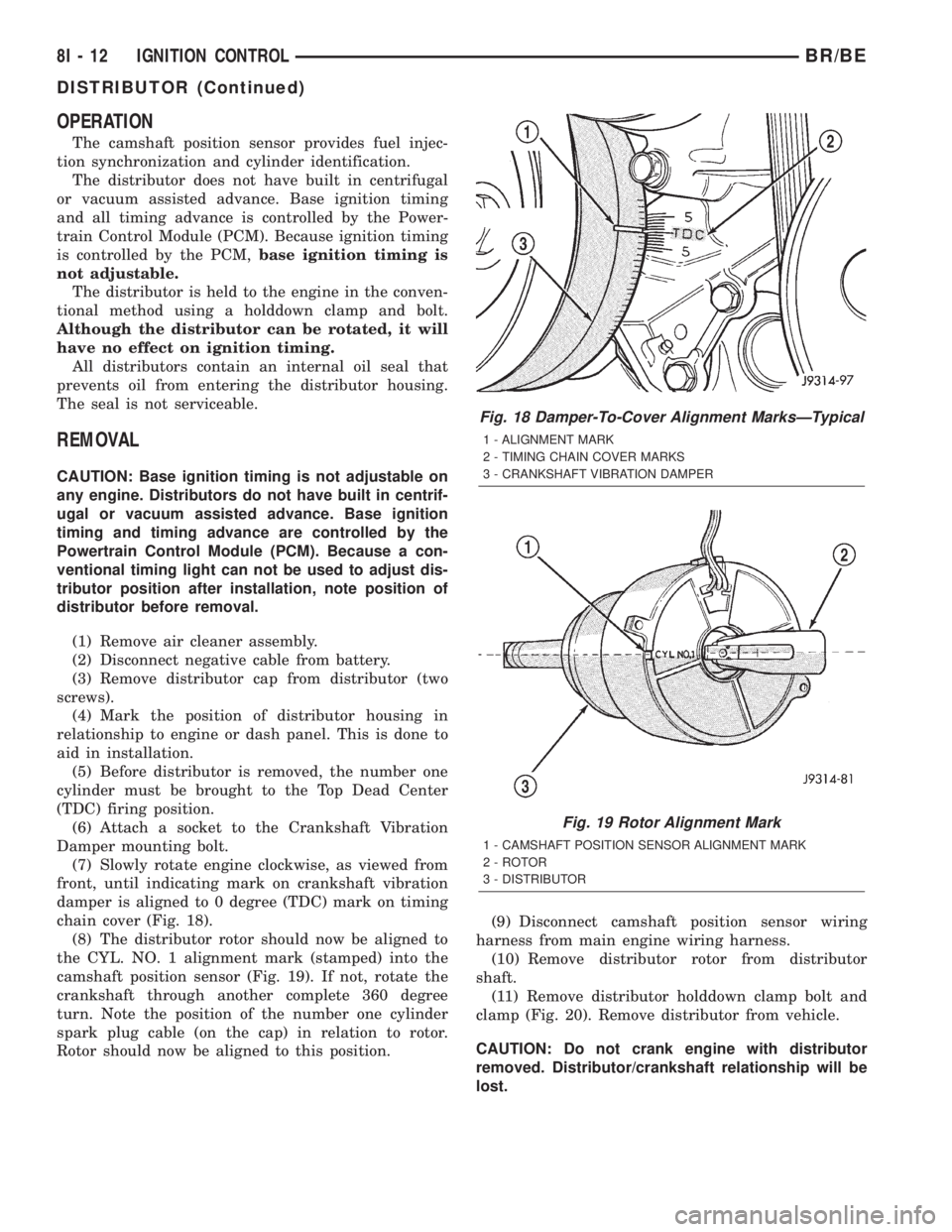
damper is aligned to 0 degree (TDC) mark on timing
chain cover (Fig. 18).
(8) The distributor rotor should now be aligned to
the CYL. NO. 1 alignment mark (stamped) into the
camshaft position sensor (Fig. 19). If not, rotate the
crankshaft through another complete 360 degree
turn. Note the position of the number one cylinder
spark plug cable (on the cap) in relation to rotor.
Rotor should now be aligned to this position.(9) Disconnect camshaft position sensor wiring
harness from main engine wiring harness.
(10) Remove distributor rotor from distributor
shaft.
(11) Remove distributor holddown clamp bolt and
clamp (Fig. 20). Remove distributor from vehicle.
CAUTION: Do not crank engine with distributor
removed. Distributor/crankshaft relationship will be
lost.
Fig. 18 Damper-To-Cover Alignment MarksÐTypical
1 - ALIGNMENT MARK
2 - TIMING CHAIN COVER MARKS
3 - CRANKSHAFT VIBRATION DAMPER
Fig. 19 Rotor Alignment Mark
1 - CAMSHAFT POSITION SENSOR ALIGNMENT MARK
2 - ROTOR
3 - DISTRIBUTOR
8I - 12 IGNITION CONTROLBR/BE
DISTRIBUTOR (Continued)
Page 470 of 2255
INSTALLATION
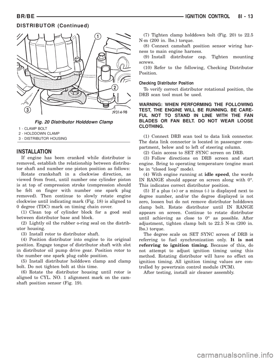
If engine has been cranked while distributor is
removed, establish the relationship between distribu-
tor shaft and number one piston position as follows:
Rotate crankshaft in a clockwise direction, as
viewed from front, until number one cylinder piston
is at top of compression stroke (compression should
be felt on finger with number one spark plug
removed). Then continue to slowly rotate engine
clockwise until indicating mark (Fig. 18) is aligned to
0 degree (TDC) mark on timing chain cover.
(1) Clean top of cylinder block for a good seal
between distributor base and block.
(2) Lightly oil the rubber o-ring seal on the distrib-
utor housing.
(3) Install rotor to distributor shaft.
(4) Position distributor into engine to its original
position. Engage tongue of distributor shaft with slot
in distributor oil pump drive gear. Position rotor to
the number one spark plug cable position.
(5) Install distributor holddown clamp and clamp
bolt. Do not tighten bolt at this time.
(6) Rotate the distributor housing until rotor is
aligned to CYL. NO. 1 alignment mark on the cam-
shaft position sensor (Fig. 19).(7) Tighten clamp holddown bolt (Fig. 20) to 22.5
N´m (200 in. lbs.) torque.
(8) Connect camshaft position sensor wiring har-
ness to main engine harness.
(9) Install distributor cap. Tighten mounting
screws.
(10) Refer to the following, Checking Distributor
Position.
Checking Distributor Position
To verify correct distributor rotational position, the
DRB scan tool must be used.
WARNING: WHEN PERFORMING THE FOLLOWING
TEST, THE ENGINE WILL BE RUNNING. BE CARE-
FUL NOT TO STAND IN LINE WITH THE FAN
BLADES OR FAN BELT. DO NOT WEAR LOOSE
CLOTHING.
(1) Connect DRB scan tool to data link connector.
The data link connector is located in passenger com-
partment, below and to left of steering column.
(2) Gain access to SET SYNC screen on DRB.
(3) Follow directions on DRB screen and start
engine. Bring to operating temperature (engine must
be in ªclosed loopº mode).
(4) With engine running atidle speed, the words
IN RANGE should appear on screen along with 0É.
This indicates correct distributor position.
(5) If a plus (+) or a minus (-) is displayed next to
degree number, and/or the degree displayed is not
zero, loosen but do not remove distributor holddown
clamp bolt. Rotate distributor until IN RANGE
appears on screen. Continue to rotate distributor
until achieving as close to 0É as possible. After
adjustment, tighten clamp bolt to 22.5 N´m (200 in.
lbs.) torque.
The degree scale on SET SYNC screen of DRB is
referring to fuel synchronization only.It is not
referring to ignition timing.Because of this, do
not attempt to adjust ignition timing using this
method. Rotating distributor will have no effect on
ignition timing. All ignition timing values are con-
trolled by powertrain control module (PCM).
After testing, install air cleaner assembly.
Fig. 20 Distributor Holddown Clamp
1 - CLAMP BOLT
2 - HOLDDOWN CLAMP
3 - DISTRIBUTOR HOUSING
BR/BEIGNITION CONTROL 8I - 13
DISTRIBUTOR (Continued)
Page 472 of 2255
IGNITION COIL
DESCRIPTION
DESCRIPTION - 5.9L
A single ignition coil is used. The coil is not oil
filled. The coil windings are embedded in an epoxy
compound. This provides heat and vibration resis-
tance that allows the coil to be mounted on the
engine.
DESCRIPTION - 8.0L
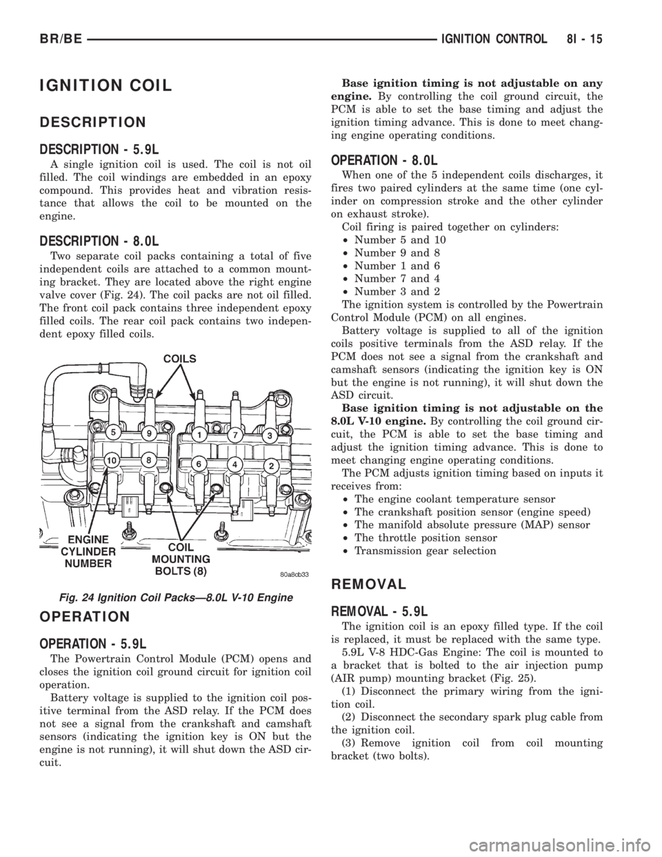
Two separate coil packs containing a total of five
independent coils are attached to a common mount-
ing bracket. They are located above the right engine
valve cover (Fig. 24). The coil packs are not oil filled.
The front coil pack contains three independent epoxy
filled coils. The rear coil pack contains two indepen-
dent epoxy filled coils.
OPERATION
OPERATION - 5.9L
The Powertrain Control Module (PCM) opens and
closes the ignition coil ground circuit for ignition coil
operation.
Battery voltage is supplied to the ignition coil pos-
itive terminal from the ASD relay. If the PCM does
not see a signal from the crankshaft and camshaft
sensors (indicating the ignition key is ON but the
engine is not running), it will shut down the ASD cir-
cuit.Base ignition timing is not adjustable on any
engine.By controlling the coil ground circuit, the
PCM is able to set the base timing and adjust the
ignition timing advance. This is done to meet chang-
ing engine operating conditions.
OPERATION - 8.0L
When one of the 5 independent coils discharges, it
fires two paired cylinders at the same time (one cyl-
inder on compression stroke and the other cylinder
on exhaust stroke).
Coil firing is paired together on cylinders:
²Number 5 and 10
²Number 9 and 8
²Number 1 and 6
²Number 7 and 4
²Number 3 and 2
The ignition system is controlled by the Powertrain
Control Module (PCM) on all engines.
Battery voltage is supplied to all of the ignition
coils positive terminals from the ASD relay. If the
PCM does not see a signal from the crankshaft and
camshaft sensors (indicating the ignition key is ON
but the engine is not running), it will shut down the
ASD circuit.
Base ignition timing is not adjustable on the
8.0L V-10 engine.By controlling the coil ground cir-
cuit, the PCM is able to set the base timing and
adjust the ignition timing advance. This is done to
meet changing engine operating conditions.
The PCM adjusts ignition timing based on inputs it
receives from:
²The engine coolant temperature sensor
²The crankshaft position sensor (engine speed)
²The manifold absolute pressure (MAP) sensor
²The throttle position sensor
²Transmission gear selection
REMOVAL
REMOVAL - 5.9L
The ignition coil is an epoxy filled type. If the coil
is replaced, it must be replaced with the same type.
5.9L V-8 HDC-Gas Engine: The coil is mounted to
a bracket that is bolted to the air injection pump
(AIR pump) mounting bracket (Fig. 25).
(1) Disconnect the primary wiring from the igni-
tion coil.
(2) Disconnect the secondary spark plug cable from
the ignition coil.
(3) Remove ignition coil from coil mounting
bracket (two bolts).
Fig. 24 Ignition Coil PacksÐ8.0L V-10 Engine
BR/BEIGNITION CONTROL 8I - 15
Page 484 of 2255
trol some of the VFD functions requires the use of a
DRBIIItscan tool. Refer to the appropriate diagnos-
tic information. Specific operation details for the
odometer and trip odometer functions of the VFD
may be found elsewhere in this service manual.
INDICATORS
Indicators are located in various positions within
the EMIC and are all connected to the EMIC circuit
board. The four-wheel drive indicator, high beam
indicator, washer fluid indicator, turn signal indica-
tors, and wait-to-start indicator are hard wired. The
brake indicator is controlled by CCD data bus mes-
sages from the Controller Anti-lock Brake (CAB) and
the hard wired park brake switch input to the EMIC.
The seatbelt indicator is controlled by the EMIC pro-
gramming, CCD data bus messages from the Airbag
Control Module (ACM), and the hard wired seat belt
switch input to the EMIC. The Malfunction Indicator
Lamp (MIL) is normally controlled by CCD data bus
messages from the Powertrain Control Module
(PCM); however, if the EMIC loses CCD data bus
communications, the EMIC circuitry will automati-
cally turn the MIL on, and flash the odometer VFD
on and off repeatedly until CCD data bus communi-
cation is restored. The EMIC uses CCD data bus
messages from the Powertrain Control Module
(PCM), the diesel engine only Engine Control Module
(ECM), the ACM, and the CAB to control all of the
remaining indicators. Different indicators are con-
trolled by different strategies; some receive fused
ignition switch output from the EMIC circuitry clus-
ter and have a switched ground, while others are
grounded through the EMIC circuitry and have a
switched battery feed.
In addition, certain indicators in this instrument
cluster are programmable or configurable. This fea-
ture allows the programmable indicators to be acti-
vated or deactivated with a DRBIIItscan tool, while
the configurable indicators will be automatically
enabled or disabled by the EMIC circuitry for com-
patibility with certain optional equipment. The only
programmable indicator for this model is the upshift
indicator. The cruise indicator, four-wheel drive indi-
cator, overdrive-off indicator, service reminder indica-
tor, and the transmission overtemp indicator are
automatically configured, either electronically or
mechanically.
The hard wired indicators are diagnosed using con-
ventional diagnostic methods. The EMIC and CCD
bus message controlled indicator lamps are diagnosed
using the EMIC self-diagnostic actuator test. (Refer
to 8 - ELECTRICAL/INSTRUMENT CLUSTER -
DIAGNOSIS AND TESTING). Proper testing of the
CCD data bus and the data bus message inputs to
the EMIC that control each indicator lamp requirethe use of a DRBIIItscan tool. Refer to the appro-
priate diagnostic information. Specific operation
details for each indicator may be found elsewhere in
this service manual.
CLUSTER ILLUMINATION
The EMIC has several illumination lamps that are
illuminated when the exterior lighting is turned on
with the headlamp switch. The illumination bright-
ness of these lamps is adjusted by the panel lamps
dimmer rheostat when the headlamp switch thumb-
wheel is rotated (down to dim, up to brighten). The
illumination lamps receive battery current through
the panel lamps dimmer rheostat and a fuse in the
JB on a fused panel lamps dimmer switch signal cir-
cuit. The illumination lamps are grounded at all
times.
In addition, an analog/digital (A/D) converter in
the EMIC converts the analog panel lamps dimmer
rheostat input from the headlamp switch to a digital
dimming level signal for controlling the lighting level
of the VFD. The EMIC also broadcasts this digital
dimming information as a message over the CCD
data bus for use by the Compass Mini-Trip Computer
(CMTC) in synchronizing the lighting level of its
VFD with that of the EMIC. The headlamp switch
thumbwheel also has a Parade position to provide a
parade mode. The EMIC monitors the request for
this mode through a hard wired day brightness sense
circuit input from the headlamp switch. In this mode,
the EMIC will override the selected panel dimmer
switch signal and send a message over the CCD data
bus to illuminate all vacuum fluorescent displays at
full brightness for easier visibility when driving in
daylight with the exterior lighting turned on. The
parade mode has no effect on the incandescent bulb
illumination intensity.
The hard wired cluster illumination lamps are
diagnosed using conventional diagnostic methods.
Proper testing of the VFD dimming level and the
CCD data bus dimming level message functions
requires the use of a DRBIIItscan tool. Refer to the
appropriate diagnostic information.
CHIME WARNING REQUESTS
The EMIC is programmed to request chime service
from the Central Timer Module (CTM) when certain
indicator lamps are illuminated. When the pro-
grammed conditions are met, the EMIC generates a
chime request signal and sends it over a hard wired
tone request circuit to the CTM. Upon receiving the
proper chime request, the CTM activates an integral
chime tone generator to provide the audible chime
tone to the vehicle operator. (Refer to 8 - ELECTRI-
CAL/CHIME/BUZZER - OPERATION). Proper test-
ing of the CTM and the EMIC chime requests
BR/BEINSTRUMENT CLUSTER 8J - 5
INSTRUMENT CLUSTER (Continued)
Page 486 of 2255
(10) Disconnect and isolate the battery negative
cable. Remove the instrument cluster. Check for con-
tinuity between the ground circuit (Z2) cavity of the
instrument panel wire harness connector (Connector
C1) and a good ground. There should be continuity. If
OK, refer to ACTUATOR TEST . If not OK, repair
the open ground circuit to ground (G200) as required.
ACTUATOR TEST
WARNING: ON VEHICLES EQUIPPED WITH AIR-
BAGS, DISABLE THE AIRBAG SYSTEM BEFORE
ATTEMPTING ANY STEERING WHEEL, STEERING
COLUMN, OR INSTRUMENT PANEL COMPONENT
DIAGNOSIS OR SERVICE. DISCONNECT AND ISO-
LATE THE BATTERY NEGATIVE (GROUND) CABLE,
THEN WAIT TWO MINUTES FOR THE AIRBAG SYS-
TEM CAPACITOR TO DISCHARGE BEFORE PER-
FORMING FURTHER DIAGNOSIS OR SERVICE. THIS
IS THE ONLY SURE WAY TO DISABLE THE AIRBAG
SYSTEM. FAILURE TO TAKE THE PROPER PRE-
CAUTIONS COULD RESULT IN ACCIDENTAL AIR-
BAG DEPLOYMENT AND POSSIBLE PERSONAL
INJURY.
The instrument cluster actuator test will put the
instrument cluster into its self-diagnostic mode. In
this mode the instrument cluster can perform a self-
diagnostic test that will confirm that the instrument
cluster circuitry, the gauges, and the CCD data bus
message-controlled indicators are capable of operat-
ing as designed. During the actuator test the instru-
ment cluster circuitry position each of the gaugeneedles at various calibration points, illuminate each
of the segments in the Vacuum-Fluorescent Display
(VFD), and turn all of the CCD data bus message-
controlled indicators on and off.
Successful completion of the actuator test will con-
firm that the instrument cluster is operational. How-
ever, there may still be a problem with the CCD data
bus, the Powertrain Control Module (PCM), the
Engine Control Module (ECM), the Airbag Control
Module (ACM), the Controller Anti-lock Brake (CAB),
or the inputs to one of these electronic control mod-
ules. Use a DRBIIItscan tool to diagnose these com-
ponents. Refer to the appropriate diagnostic
information.
(1) Begin the test with the ignition switch in the
Off position.
(2) Depress the odometer/trip odometer switch but-
ton.
(3) While still holding the odometer/trip odometer
switch button depressed, turn the ignition switch to
the On position, but do not start the engine.
(4) Keep the odometer/trip odometer switch button
depressed for about ten seconds, untilCHEC
appears in the odometer display, then release the
odometer/trip odometer switch button.
(5) A series of three-digit numeric failure messages
may appear in the odometer display, depending upon
the failure mode. If a failure message appears, refer
to the Instrument Cluster Failure Message chart for
the description and proper correction. If no failure
message appears, the actuator test will proceed as
described in Step 6.
INSTRUMENT CLUSTER FAILURE MESSAGE
Message Description Correction
110 A failure has been identified in the cluster
CPU, RAM, or EEPROM.1. Replace the faulty cluster.
900 The CCD data bus is not operational. 1. Check the CCD data bus connections at the
cluster.
2. Check the cluster fuses.
3. Check the CCD data bus bias.
4. Check the CCD data bus voltage.
5. Check the CCD data bus terminations.
920 The cluster is not receiving a vehicle speed
message from the PCM.1. Check the PCM software level and reflash if
required.
2. Use a DRBIIITscan tool to verify that the
vehicle speed message is being sent by the
PCM.
921 The cluster is not receiving a distance pulse
message from the PCM.1. Check the PCM software level and reflash if
required.
2. Use a DRBIIITscan tool to verify that the
distance pulse message is being sent by the
PCM.
BR/BEINSTRUMENT CLUSTER 8J - 7
INSTRUMENT CLUSTER (Continued)
Page 487 of 2255
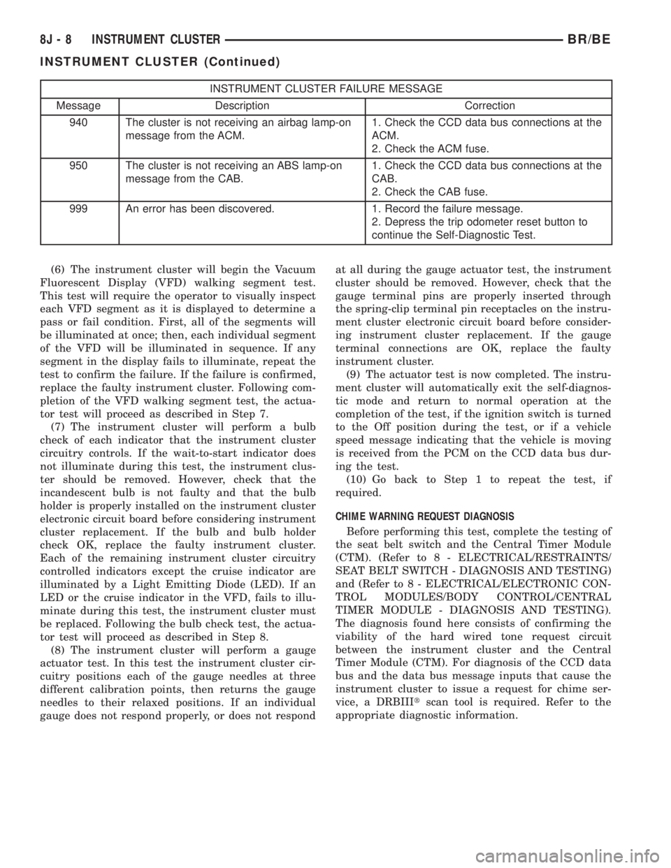
INSTRUMENT CLUSTER FAILURE MESSAGE
Message Description Correction
940 The cluster is not receiving an airbag lamp-on
message from the ACM.1. Check the CCD data bus connections at the
ACM.
2. Check the ACM fuse.
950 The cluster is not receiving an ABS lamp-on
message from the CAB.1. Check the CCD data bus connections at the
CAB.
2. Check the CAB fuse.
999 An error has been discovered. 1. Record the failure message.
2. Depress the trip odometer reset button to
continue the Self-Diagnostic Test.
(6) The instrument cluster will begin the Vacuum
Fluorescent Display (VFD) walking segment test.
This test will require the operator to visually inspect
each VFD segment as it is displayed to determine a
pass or fail condition. First, all of the segments will
be illuminated at once; then, each individual segment
of the VFD will be illuminated in sequence. If any
segment in the display fails to illuminate, repeat the
test to confirm the failure. If the failure is confirmed,
replace the faulty instrument cluster. Following com-
pletion of the VFD walking segment test, the actua-
tor test will proceed as described in Step 7.
(7) The instrument cluster will perform a bulb
check of each indicator that the instrument cluster
circuitry controls. If the wait-to-start indicator does
not illuminate during this test, the instrument clus-
ter should be removed. However, check that the
incandescent bulb is not faulty and that the bulb
holder is properly installed on the instrument cluster
electronic circuit board before considering instrument
cluster replacement. If the bulb and bulb holder
check OK, replace the faulty instrument cluster.
Each of the remaining instrument cluster circuitry
controlled indicators except the cruise indicator are
illuminated by a Light Emitting Diode (LED). If an
LED or the cruise indicator in the VFD, fails to illu-
minate during this test, the instrument cluster must
be replaced. Following the bulb check test, the actua-
tor test will proceed as described in Step 8.
(8) The instrument cluster will perform a gauge
actuator test. In this test the instrument cluster cir-
cuitry positions each of the gauge needles at three
different calibration points, then returns the gauge
needles to their relaxed positions. If an individual
gauge does not respond properly, or does not respondat all during the gauge actuator test, the instrument
cluster should be removed. However, check that the
gauge terminal pins are properly inserted through
the spring-clip terminal pin receptacles on the instru-
ment cluster electronic circuit board before consider-
ing instrument cluster replacement. If the gauge
terminal connections are OK, replace the faulty
instrument cluster.
(9) The actuator test is now completed. The instru-
ment cluster will automatically exit the self-diagnos-
tic mode and return to normal operation at the
completion of the test, if the ignition switch is turned
to the Off position during the test, or if a vehicle
speed message indicating that the vehicle is moving
is received from the PCM on the CCD data bus dur-
ing the test.
(10) Go back to Step 1 to repeat the test, if
required.
CHIME WARNING REQUEST DIAGNOSIS
Before performing this test, complete the testing of
the seat belt switch and the Central Timer Module
(CTM). (Refer to 8 - ELECTRICAL/RESTRAINTS/
SEAT BELT SWITCH - DIAGNOSIS AND TESTING)
and (Refer to 8 - ELECTRICAL/ELECTRONIC CON-
TROL MODULES/BODY CONTROL/CENTRAL
TIMER MODULE - DIAGNOSIS AND TESTING).
The diagnosis found here consists of confirming the
viability of the hard wired tone request circuit
between the instrument cluster and the Central
Timer Module (CTM). For diagnosis of the CCD data
bus and the data bus message inputs that cause the
instrument cluster to issue a request for chime ser-
vice, a DRBIIItscan tool is required. Refer to the
appropriate diagnostic information.
8J - 8 INSTRUMENT CLUSTERBR/BE
INSTRUMENT CLUSTER (Continued)
Page 496 of 2255

brake switch sense circuit between the park brake
switch and the instrument cluster as required.
(3) Check for continuity between the park brake
switch sense circuit cavities of the instrument panel
wire harness connector for the park brake switch and
the instrument panel wire harness connector (Con-
nector C1) for the instrument cluster. There should
be continuity. If OK, proceed with diagnosis of the
instrument cluster. (Refer to 8 - ELECTRICAL/IN-
STRUMENT CLUSTER - DIAGNOSIS AND TEST-
ING). If not OK, repair the open park brake switch
sense circuit between the park brake switch and the
instrument cluster as required.
CHECK GAUGES INDICATOR
DESCRIPTION
A check gauges indicator is standard equipment on
all instrument clusters. The check gauges indicator is
located on the lower edge of the instrument cluster
overlay, to the right of center. The check gauges indi-
cator consists of a stenciled cutout of the words
ªCHECK GAGESº in the opaque layer of the instru-
ment cluster overlay. The dark outer layer of the
overlay prevents the indicator from being clearly vis-
ible when it is not illuminated. A red lens behind the
cutout in the opaque layer of the overlay causes the
ªCHECK GAGESº text to appear in red through the
translucent outer layer of the overlay when the indi-
cator is illuminated from behind by a Light Emitting
Diode (LED) soldered onto the instrument cluster
electronic circuit board. The check gauges indicator is
serviced as a unit with the instrument cluster.
OPERATION
The check gauges indicator gives an indication to
the vehicle operator when certain instrument cluster
gauge readings reflect a condition requiring immedi-
ate attention. This indicator is controlled by a tran-
sistor on the instrument cluster circuit board based
upon the cluster programming and electronic mes-
sages received by the cluster from the Powertrain
Control Module (PCM) over the Chrysler Collision
Detection (CCD) data bus. The check gauges indica-
tor Light Emitting Diode (LED) receives battery cur-
rent on the instrument cluster electronic circuit
board through the fused ignition switch output (st-
run) circuit whenever the ignition switch is in the On
or Start positions; therefore, the LED will always be
off when the ignition switch is in any position except
On or Start. The LED only illuminates when it is
provided a path to ground by the instrument cluster
transistor. The instrument cluster will turn on the
check gauges indicator for the following reasons:²Bulb Test- Each time the ignition switch is
turned to the On position the check gauges indicator
is illuminated for about two seconds as a bulb test.
²Engine Temperature High Message- Each
time the cluster receives a message from the PCM
indicating the engine coolant temperature of a gaso-
line engine is about 122É C (253É F) or higher, or a
diesel engine is about 112É C (233É F) or higher, the
check gauges indicator will be illuminated. The indi-
cator remains illuminated until the cluster receives a
message from the PCM indicating that the tempera-
ture of a gasoline engine is about 119É C (246É F) or
lower, a diesel engine is about 109É C (226É F) or
lower, or until the ignition switch is turned to the Off
position, whichever occurs first.
²Engine Oil Pressure Low Message- Each
time the cluster receives a message from the PCM
indicating the engine oil pressure of a gasoline
engine is about 3.45 kPa (0.5 psi) or lower, or a diesel
engine is about 51.71 kPa (7.5 psi) or lower, the
check gauges indicator will be illuminated. The indi-
cator remains illuminated until the cluster receives a
message from the PCM indicating that the engine oil
pressure of a gasoline engine is above 3.45 kPa (0.5
psi), a diesel engine is above 51.71 kPa (7.5 psi), or
until the ignition switch is turned to the Off position,
whichever occurs first. The cluster will only turn the
indicator on in response to an engine oil pressure low
message if the engine speed is greater than zero.
²System Voltage Low Message- Each time the
cluster receives a message from the PCM indicating
the electrical system voltage is less than 11.5 volts,
the check gauges indicator will be illuminated. The
indicator remains illuminated until the cluster
receives a message from the PCM indicating the elec-
trical system voltage is greater than 12.0 volts (but
less than 16.6 volts), or until the ignition switch is
turned to the Off position, whichever occurs first.
²System Voltage High Message- Each time
the cluster receives a message from the PCM indicat-
ing the electrical system voltage is greater than 16.6
volts, the check gauges indicator will be illuminated.
The indicator remains illuminated until the cluster
receives a message from the PCM indicating the elec-
trical system voltage is less than 16.1 volts (but
greater than 11.5 volts), or until the ignition switch
is turned to the Off position, whichever occurs first.
²Actuator Test- Each time the cluster is put
through the actuator test, the indicator will be
turned on during the bulb check portion of the test to
confirm the functionality of the LED and the cluster
control circuitry.
The PCM continually monitors the engine temper-
ature, oil pressure, and electrical system voltage,
then sends the proper messages to the instrument
cluster. For further diagnosis of the check gauges
BR/BEINSTRUMENT CLUSTER 8J - 17
BRAKE/PARK BRAKE INDICATOR (Continued)