DODGE RAM 2002 Service Repair Manual
Manufacturer: DODGE, Model Year: 2002, Model line: RAM, Model: DODGE RAM 2002Pages: 2255, PDF Size: 62.07 MB
Page 451 of 2255

Page 452 of 2255
HORN
TABLE OF CONTENTS
page page
HORN
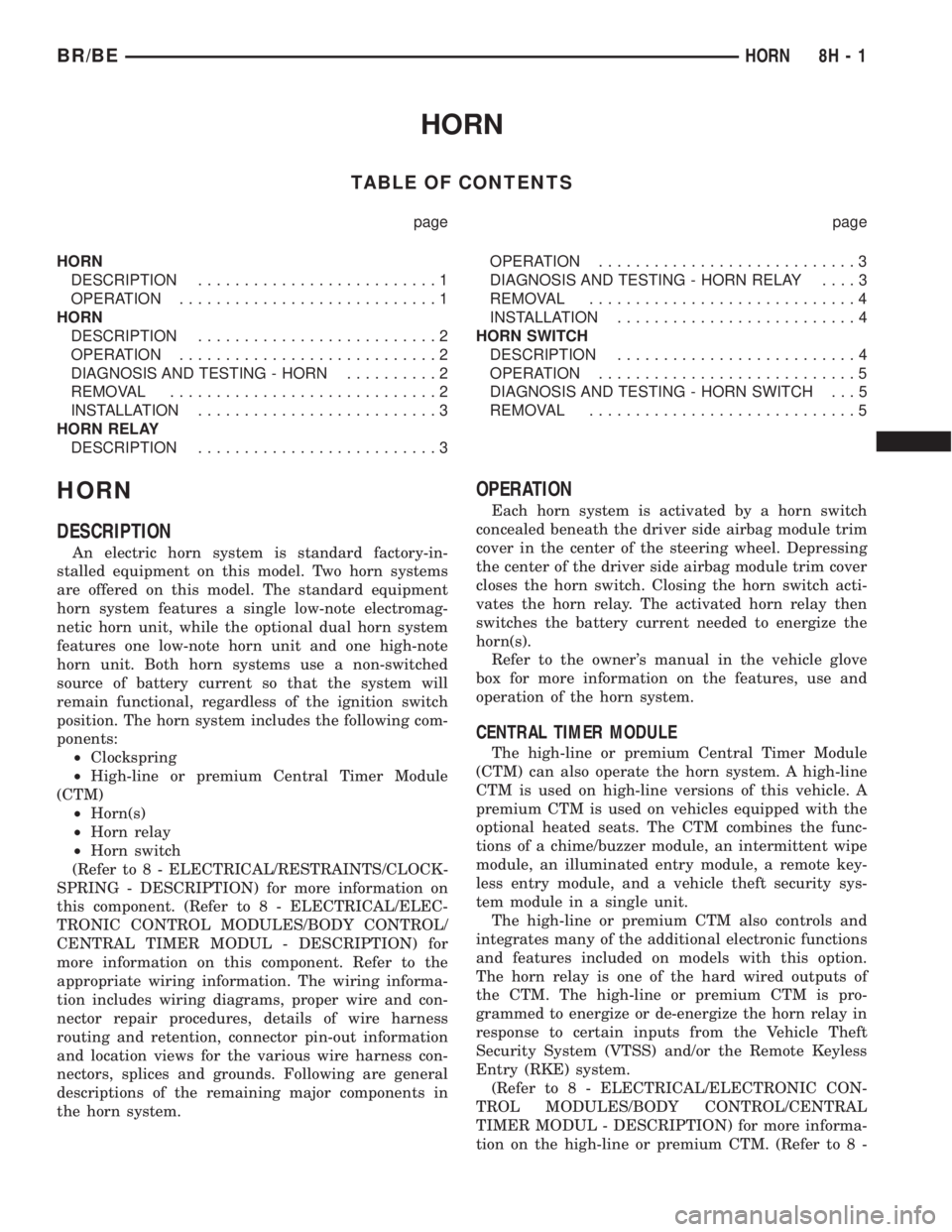
DESCRIPTION..........................1
OPERATION............................1
HORN
DESCRIPTION..........................2
OPERATION............................2
DIAGNOSIS AND TESTING - HORN..........2
REMOVAL.............................2
INSTALLATION..........................3
HORN RELAY
DESCRIPTION..........................3OPERATION............................3
DIAGNOSIS AND TESTING - HORN RELAY....3
REMOVAL.............................4
INSTALLATION..........................4
HORN SWITCH
DESCRIPTION..........................4
OPERATION............................5
DIAGNOSIS AND TESTING - HORN SWITCH . . . 5
REMOVAL.............................5
HORN
DESCRIPTION
An electric horn system is standard factory-in-
stalled equipment on this model. Two horn systems
are offered on this model. The standard equipment
horn system features a single low-note electromag-
netic horn unit, while the optional dual horn system
features one low-note horn unit and one high-note
horn unit. Both horn systems use a non-switched
source of battery current so that the system will
remain functional, regardless of the ignition switch
position. The horn system includes the following com-
ponents:
²Clockspring
²High-line or premium Central Timer Module
(CTM)
²Horn(s)
²Horn relay
²Horn switch
(Refer to 8 - ELECTRICAL/RESTRAINTS/CLOCK-
SPRING - DESCRIPTION) for more information on
this component. (Refer to 8 - ELECTRICAL/ELEC-
TRONIC CONTROL MODULES/BODY CONTROL/
CENTRAL TIMER MODUL - DESCRIPTION) for
more information on this component. Refer to the
appropriate wiring information. The wiring informa-
tion includes wiring diagrams, proper wire and con-
nector repair procedures, details of wire harness
routing and retention, connector pin-out information
and location views for the various wire harness con-
nectors, splices and grounds. Following are general
descriptions of the remaining major components in
the horn system.
OPERATION
Each horn system is activated by a horn switch
concealed beneath the driver side airbag module trim
cover in the center of the steering wheel. Depressing
the center of the driver side airbag module trim cover
closes the horn switch. Closing the horn switch acti-
vates the horn relay. The activated horn relay then
switches the battery current needed to energize the
horn(s).
Refer to the owner's manual in the vehicle glove
box for more information on the features, use and
operation of the horn system.
CENTRAL TIMER MODULE
The high-line or premium Central Timer Module
(CTM) can also operate the horn system. A high-line
CTM is used on high-line versions of this vehicle. A
premium CTM is used on vehicles equipped with the
optional heated seats. The CTM combines the func-
tions of a chime/buzzer module, an intermittent wipe
module, an illuminated entry module, a remote key-
less entry module, and a vehicle theft security sys-
tem module in a single unit.
The high-line or premium CTM also controls and
integrates many of the additional electronic functions
and features included on models with this option.
The horn relay is one of the hard wired outputs of
the CTM. The high-line or premium CTM is pro-
grammed to energize or de-energize the horn relay in
response to certain inputs from the Vehicle Theft
Security System (VTSS) and/or the Remote Keyless
Entry (RKE) system.
(Refer to 8 - ELECTRICAL/ELECTRONIC CON-
TROL MODULES/BODY CONTROL/CENTRAL
TIMER MODUL - DESCRIPTION) for more informa-
tion on the high-line or premium CTM. (Refer to 8 -
BR/BEHORN 8H - 1
Page 453 of 2255
ELECTRICAL/VEHICLE THEFT SECURITY - GEN-
ERAL INFORMATION) for more information on the
VTSS. (Refer to 8 - ELECTRICAL/POWER LOCKS -
GENERAL INFORMATION) for more information on
the RKE system.
HORN
DESCRIPTION
The standard single, low-note, electromagnetic dia-
phragm-type horn is secured with a bracket to the
right front fender wheel house extension in the
engine compartment. The high-note horn for the
optional dual-note horn system is connected in paral-
lel with and secured with a bracket just forward of
the low-note horn. Each horn is grounded through its
wire harness connector and circuit to a ground splice
joint connector, and receives battery feed through the
closed contacts of the horn relay.
The horns cannot be repaired or adjusted and, if
faulty or damaged, they must be individually
replaced.
OPERATION
Within the two halves of the molded plastic horn
housing are a flexible diaphragm, a plunger, an elec-
tromagnetic coil and a set of contact points. The dia-
phragm is secured in suspension around its
perimeter by the mating surfaces of the horn hous-
ing. The plunger is secured to the center of the dia-
phragm and extends into the center of the
electromagnet. The contact points control the current
flow through the electromagnet.
When the horn is energized, electrical current
flows through the closed contact points to the electro-
magnet. The resulting electromagnetic field draws
the plunger and diaphragm toward it until that
movement mechanically opens the contact points.
When the contact points open, the electromagnetic
field collapses allowing the plunger and diaphragm to
return to their relaxed positions and closing the con-
tact points again. This cycle continues repeating at a
very rapid rate producing the vibration and move-
ment of air that creates the sound that is directed
through the horn outlet.
DIAGNOSIS AND TESTING - HORN
For complete circuit diagrams, refer to the appro-
priate wiring information. The wiring information
includes wiring diagrams, proper wire and connector
repair procedures, details of wire harness routing
and retention, connector pin-out information and
location views for the various wire harness connec-
tors, splices and grounds.(1) Disconnect the wire harness connector(s) from
the horn connector receptacle(s). Measure the resis-
tance between the ground circuit cavity of the horn(s)
wire harness connector(s) and a good ground. There
should be no measurable resistance. If OK, go to Step
2. If not OK, repair the open ground circuit to ground
as required.
(2) Check for battery voltage at the horn relay out-
put circuit cavity of the horn(s) wire harness connec-
tor(s). There should be zero volts. If OK, go to Step 3.
If not OK, repair the shorted horn relay output cir-
cuit or replace the faulty horn relay as required.
(3) Depress the horn switch. There should now be
battery voltage at the horn relay output circuit cavity
of the horn(s) wire harness connector(s). If OK,
replace the faulty horn(s). If not OK, repair the open
horn relay output circuit to the horn relay as
required.
REMOVAL
(1) Disconnect and isolate the battery negative
cable.
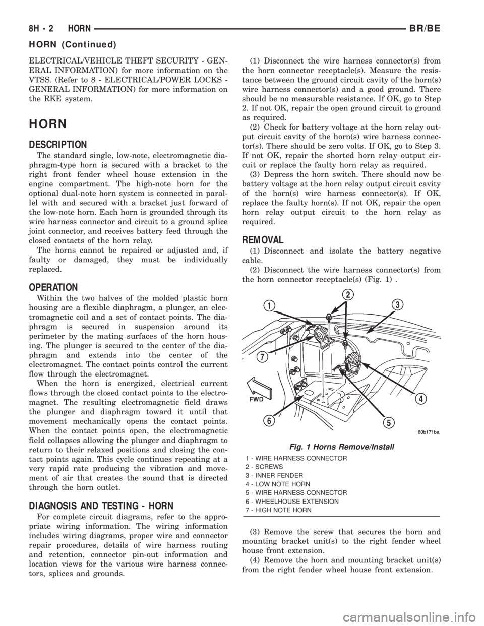
(2) Disconnect the wire harness connector(s) from
the horn connector receptacle(s) (Fig. 1) .
(3) Remove the screw that secures the horn and
mounting bracket unit(s) to the right fender wheel
house front extension.
(4) Remove the horn and mounting bracket unit(s)
from the right fender wheel house front extension.
Fig. 1 Horns Remove/Install
1 - WIRE HARNESS CONNECTOR
2 - SCREWS
3 - INNER FENDER
4 - LOW NOTE HORN
5 - WIRE HARNESS CONNECTOR
6 - WHEELHOUSE EXTENSION
7 - HIGH NOTE HORN
8H - 2 HORNBR/BE
HORN (Continued)
Page 454 of 2255
INSTALLATION
(1) Position the horn and mounting bracket unit(s)
onto the right fender wheel house front extension.
(2) Install and tighten the screw that secures the
horn and mounting bracket unit(s) to the right
fender wheel house front extension. Tighten the
screw to 11 N´m (95 in. lbs.).
(3) Reconnect the wire harness connector(s) to the
horn connector receptacle(s).
(4) Reconnect the battery negative cable.
HORN RELAY
DESCRIPTION
The horn relay is a electromechanical device that
switches battery current to the horn when the horn
switch grounds the relay coil. The horn relay is
located in the Power Distribution Center (PDC) in
the engine compartment. If a problem is encountered
with a continuously sounding horn, it can usually be
quickly resolved by removing the horn relay from the
PDC until further diagnosis is completed. See the
fuse and relay layout label affixed to the inside sur-
face of the PDC cover for horn relay identification
and location.
The horn relay is a International Standards Orga-
nization (ISO) micro-relay. Relays conforming to the
ISO specifications have common physical dimensions,
current capacities, terminal patterns, and terminal
functions. The ISO micro-relay terminal functions
are the same as a conventional ISO relay. However,
the ISO micro-relay terminal pattern (or footprint) is
different, the current capacity is lower, and the phys-
ical dimensions are smaller than those of the conven-
tional ISO relay.
The horn relay cannot be repaired or adjusted and,
if faulty or damaged, it must be replaced.
OPERATION
The ISO relay consists of an electromagnetic coil, a
resistor or diode, and three (two fixed and one mov-
able) electrical contacts. The movable (common feed)
relay contact is held against one of the fixed contacts
(normally closed) by spring pressure. When the elec-
tromagnetic coil is energized, it draws the movable
contact away from the normally closed fixed contact,
and holds it against the other (normally open) fixed
contact.
When the electromagnetic coil is de-energized,
spring pressure returns the movable contact to the
normally closed position. The resistor or diode is con-
nected in parallel with the electromagnetic coil in the
relay, and helps to dissipate voltage spikes that are
produced when the coil is de-energized.
DIAGNOSIS AND TESTING - HORN RELAY
The horn relay (Fig. 2) is located in the Power Dis-
tribution Center (PDC) behind the battery on the
driver side of the engine compartment. If a problem
is encountered with a continuously sounding horn, it
can usually be quickly resolved by removing the horn
relay from the PDC until further diagnosis is com-
pleted. See the fuse and relay layout label affixed to
the inside surface of the PDC cover for horn relay
identification and location. For complete circuit dia-
grams, refer to the appropriate wiring information.
The wiring information includes wiring diagrams,
proper wire and connector repair procedures, details
of wire harness routing and retention, connector pin-
out information and location views for the various
wire harness connectors, splices and grounds.
WARNING: ON VEHICLES EQUIPPED WITH AIR-
BAGS, REFER TO ELECTRICAL, RESTRAINTS
BEFORE ATTEMPTING ANY STEERING WHEEL,
STEERING COLUMN, OR INSTRUMENT PANEL
COMPONENT DIAGNOSIS OR SERVICE. FAILURE
TO TAKE THE PROPER PRECAUTIONS COULD
RESULT IN ACCIDENTAL AIRBAG DEPLOYMENT
AND POSSIBLE PERSONAL INJURY.
(1) Remove the horn relay from the PDC. (Refer to
8 - ELECTRICAL/HORN/HORN RELAY -
REMOVAL) for the procedures.
(2) A relay in the de-energized position should
have continuity between terminals 87A and 30, and
no continuity between terminals 87 and 30. If OK, go
to Step 3. If not OK, replace the faulty relay.
(3) Resistance between terminals 85 and 86 (elec-
tromagnet) should be 75 5 ohms. If OK, go to Step
4. If not OK, replace the faulty relay.
(4) Connect a battery to terminals 85 and 86.
There should now be continuity between terminals
30 and 87, and no continuity between terminals 87A
and 30. If OK, perform the Relay Circuit Test that
follows. If not OK, replace the faulty relay.
RELAY CIRCUIT TEST
(1) The relay common feed terminal cavity (30) is
connected to battery voltage and should be hot at all
times. If OK, go to Step 2. If not OK, repair the open
circuit to the fuse in the PDC as required.
(2) The relay normally closed terminal (87A) is
connected to terminal 30 in the de-energized position,
but is not used for this application. Go to Step 3.
(3) The relay normally open terminal (87) is con-
nected to the common feed terminal (30) in the ener-
gized position. This terminal supplies battery voltage
to the horn(s). There should be continuity between
the cavity for relay terminal 87 and the horn relay
output circuit cavity of each horn wire harness con-
BR/BEHORN 8H - 3
HORN (Continued)
Page 455 of 2255
nector at all times. If OK, go to Step 4. If not OK,
repair the open circuit to the horn(s) as required.
(4) The coil battery terminal (86) is connected to
the electromagnet in the relay. It is connected to bat-
tery voltage and should be hot at all times. Check for
battery voltage at the cavity for relay terminal 86. If
OK, go to Step 5. If not OK, repair the open circuit to
the fuse in the PDC as required.
(5) The coil ground terminal (85) is connected to
the electromagnet in the relay. It is grounded
through the horn switch when the horn switch is
depressed. On vehicles equipped with the Vehicle
Theft Security System (VTSS), the horn relay coil
ground terminal can also be grounded by the Central
Timer Module (CTM) in response to certain inputs
related to the VTSS or Remote Keyless Entry (RKE)
system. Check for continuity to ground at the cavity
for relay terminal 85. There should be continuity
with the horn switch depressed, and no continuity
with the horn switch released. If not OK, (Refer to 8
- ELECTRICAL/HORN/HORN SWITCH - DIAGNO-
SIS AND TESTING).
REMOVAL
(1) Disconnect and isolate the battery negative
cable.
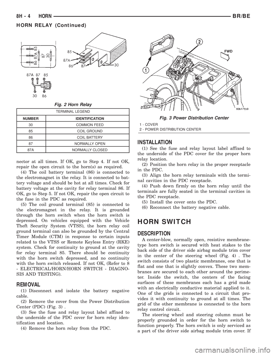
(2) Remove the cover from the Power Distribution
Center (PDC) (Fig. 3) .
(3) See the fuse and relay layout label affixed to
the underside of the PDC cover for horn relay iden-
tification and location.
(4) Remove the horn relay from the PDC.
INSTALLATION
(1) See the fuse and relay layout label affixed to
the underside of the PDC cover for the proper horn
relay location.
(2) Position the horn relay in the proper receptacle
in the PDC.
(3) Align the horn relay terminals with the termi-
nal cavities in the PDC receptacle.
(4) Push down firmly on the horn relay until the
terminals are fully seated in the terminal cavities in
the PDC receptacle.
(5) Install the cover onto the PDC.
(6) Reconnect the battery negative cable.
HORN SWITCH
DESCRIPTION
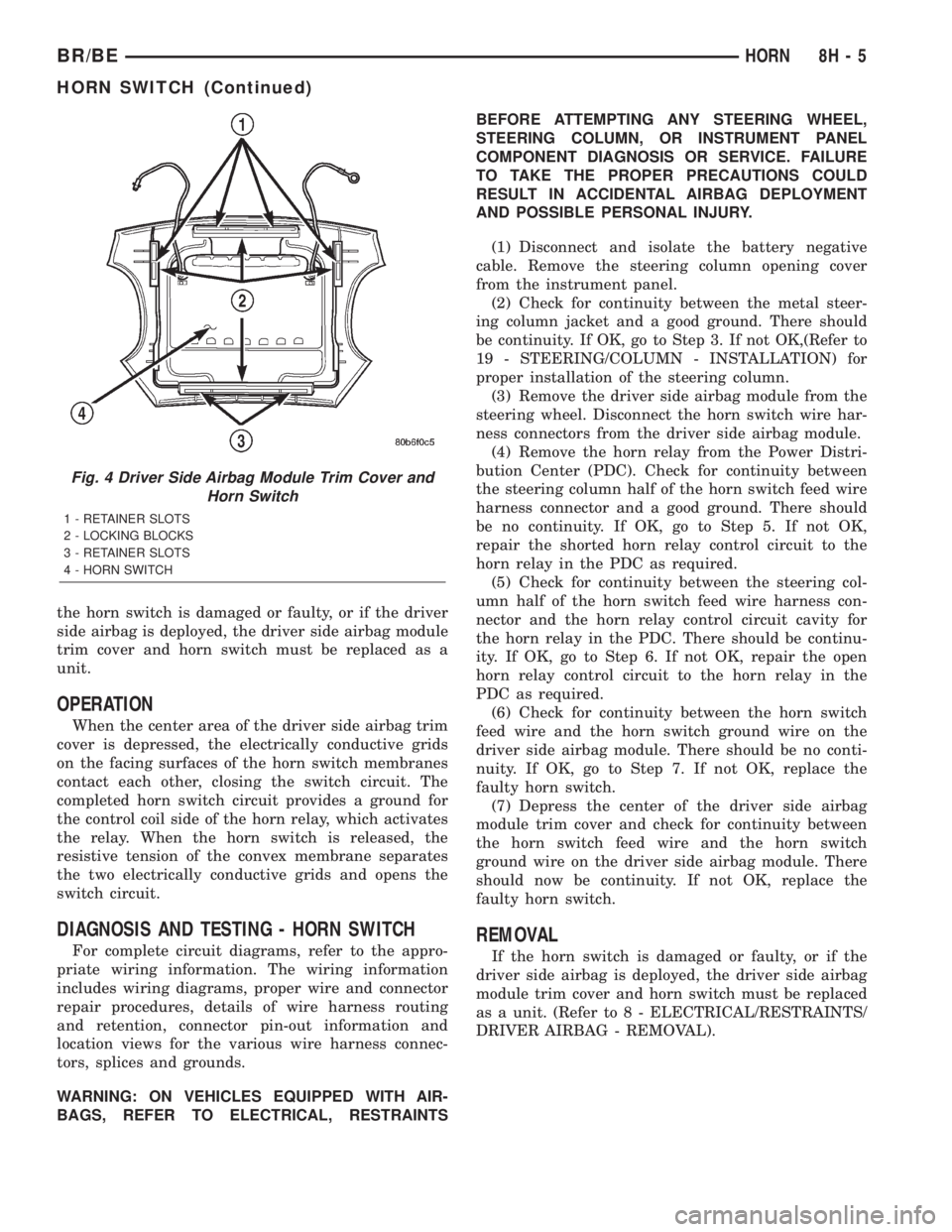
A center-blow, normally open, resistive membrane-
type horn switch is secured with heat stakes to the
back side of the driver side airbag module trim cover
in the center of the steering wheel (Fig. 4) . The
switch consists of two plastic membranes, one that is
flat and one that is slightly convex. These two mem-
branes are secured to each other around the perime-
ter. Inside the switch, the centers of the facing
surfaces of these membranes each has a grid made
with an electrically conductive material applied to it.
One of the grids is connected to a circuit that pro-
vides it with continuity to ground at all times. The
grid of the other membrane is connected to the horn
relay control circuit.
The steering wheel and steering column must be
properly grounded in order for the horn switch to
function properly. The horn switch is only serviced as
a part of the driver side airbag module trim cover. If
Fig. 2 Horn Relay
TERMINAL LEGEND
NUMBER IDENTIFICATION
30 COMMON FEED
85 COIL GROUND
86 COIL BATTERY
87 NORMALLY OPEN
87A NORMALLY CLOSED
Fig. 3 Power Distribution Center
1 - COVER
2 - POWER DISTRIBUTION CENTER
8H - 4 HORNBR/BE
HORN RELAY (Continued)
Page 456 of 2255
the horn switch is damaged or faulty, or if the driver
side airbag is deployed, the driver side airbag module
trim cover and horn switch must be replaced as a
unit.
OPERATION
When the center area of the driver side airbag trim
cover is depressed, the electrically conductive grids
on the facing surfaces of the horn switch membranes
contact each other, closing the switch circuit. The
completed horn switch circuit provides a ground for
the control coil side of the horn relay, which activates
the relay. When the horn switch is released, the
resistive tension of the convex membrane separates
the two electrically conductive grids and opens the
switch circuit.
DIAGNOSIS AND TESTING - HORN SWITCH
For complete circuit diagrams, refer to the appro-
priate wiring information. The wiring information
includes wiring diagrams, proper wire and connector
repair procedures, details of wire harness routing
and retention, connector pin-out information and
location views for the various wire harness connec-
tors, splices and grounds.
WARNING: ON VEHICLES EQUIPPED WITH AIR-
BAGS, REFER TO ELECTRICAL, RESTRAINTSBEFORE ATTEMPTING ANY STEERING WHEEL,
STEERING COLUMN, OR INSTRUMENT PANEL
COMPONENT DIAGNOSIS OR SERVICE. FAILURE
TO TAKE THE PROPER PRECAUTIONS COULD
RESULT IN ACCIDENTAL AIRBAG DEPLOYMENT
AND POSSIBLE PERSONAL INJURY.
(1) Disconnect and isolate the battery negative
cable. Remove the steering column opening cover
from the instrument panel.
(2) Check for continuity between the metal steer-
ing column jacket and a good ground. There should
be continuity. If OK, go to Step 3. If not OK,(Refer to
19 - STEERING/COLUMN - INSTALLATION) for
proper installation of the steering column.
(3) Remove the driver side airbag module from the
steering wheel. Disconnect the horn switch wire har-
ness connectors from the driver side airbag module.
(4) Remove the horn relay from the Power Distri-
bution Center (PDC). Check for continuity between
the steering column half of the horn switch feed wire
harness connector and a good ground. There should
be no continuity. If OK, go to Step 5. If not OK,
repair the shorted horn relay control circuit to the
horn relay in the PDC as required.
(5) Check for continuity between the steering col-
umn half of the horn switch feed wire harness con-
nector and the horn relay control circuit cavity for
the horn relay in the PDC. There should be continu-
ity. If OK, go to Step 6. If not OK, repair the open
horn relay control circuit to the horn relay in the
PDC as required.
(6) Check for continuity between the horn switch
feed wire and the horn switch ground wire on the
driver side airbag module. There should be no conti-
nuity. If OK, go to Step 7. If not OK, replace the
faulty horn switch.
(7) Depress the center of the driver side airbag
module trim cover and check for continuity between
the horn switch feed wire and the horn switch
ground wire on the driver side airbag module. There
should now be continuity. If not OK, replace the
faulty horn switch.REMOVAL
If the horn switch is damaged or faulty, or if the
driver side airbag is deployed, the driver side airbag
module trim cover and horn switch must be replaced
as a unit. (Refer to 8 - ELECTRICAL/RESTRAINTS/
DRIVER AIRBAG - REMOVAL).
Fig. 4 Driver Side Airbag Module Trim Cover and
Horn Switch
1 - RETAINER SLOTS
2 - LOCKING BLOCKS
3 - RETAINER SLOTS
4 - HORN SWITCH
BR/BEHORN 8H - 5
HORN SWITCH (Continued)
Page 457 of 2255

Page 458 of 2255
IGNITION CONTROL
TABLE OF CONTENTS
page page
IGNITION CONTROL
DESCRIPTION - 8.0L V-10.................2
OPERATION
OPERATION - 8.0L V-10.................2
OPERATION - V-8......................2
SPECIFICATIONS
SPECIFICATIONS - TORQUE - IGNITION....2
SPARK PLUG CABLE ORDERÐ8.0L V-10
ENGINE..............................3
ENGINE FIRING ORDERÐ5.9L V-8
ENGINES............................3
SPARK PLUG CABLE RESISTANCE........3
SPARK PLUGS........................3
IGNITION COIL RESISTANCEÐ5.9L
ENGINES............................3
IGNITION COIL RESISTANCEÐ8.0L V-10
ENGINE..............................4
IGNITION TIMING......................4
AUTOMATIC SHUT DOWN RELAY
DESCRIPTION - PCM OUTPUT.............4
OPERATION
OPERATION - PCM OUTPUT.............4
OPERATION - ASD SENSE - PCM INPUT....4
DIAGNOSIS AND TESTING - ASD AND FUEL
PUMP RELAYS........................4
REMOVAL.............................5
INSTALLATION..........................5
CAMSHAFT POSITION SENSOR
DESCRIPTION
DESCRIPTION - DIESEL.................6
DESCRIPTION - 5.9L....................6
DESCRIPTION - 8.0L....................6
OPERATION
OPERATION - DIESEL...................6
OPERATION - 5.9L.....................7
OPERATION - 8.0L.....................7
REMOVAL
REMOVAL - DIESEL....................7
REMOVAL - 5.9L.......................7
REMOVAL - 8.0L.......................8
INSTALLATION
INSTALLATION - DIESEL.................9INSTALLATION - 5.9L..................10
INSTALLATION - 8.0L..................10
DISTRIBUTOR
DESCRIPTION.........................11
OPERATION...........................12
REMOVAL.............................12
INSTALLATION.........................13
DISTRIBUTOR CAP
DIAGNOSIS AND TESTING - DISTRIBUTOR
CAP ................................14
DISTRIBUTOR ROTOR
DIAGNOSIS AND TESTING - DISTRIBUTOR
ROTOR .............................14
IGNITION COIL
DESCRIPTION
DESCRIPTION - 5.9L...................15
DESCRIPTION - 8.0L...................15
OPERATION
OPERATION - 5.9L....................15
OPERATION - 8.0L....................15
REMOVAL
REMOVAL - 5.9L......................15
REMOVAL - 8.0L......................16
INSTALLATION
INSTALLATION - 5.9L..................16
INSTALLATION - 8.0L..................16
SPARK PLUG
DESCRIPTION.........................16
OPERATION...........................16
DIAGNOSIS AND TESTING - SPARK PLUG
CONDITIONS.........................17
REMOVAL.............................19
CLEANING............................20
INSTALLATION.........................20
SPARK PLUG CABLE
DESCRIPTION.........................20
OPERATION...........................20
DIAGNOSIS AND TESTING - SPARK PLUG
CABLES............................20
REMOVAL.............................21
INSTALLATION.........................21
BR/BEIGNITION CONTROL 8I - 1
Page 459 of 2255
IGNITION CONTROL
DESCRIPTION - 8.0L V-10
The ignition system used on the 8.0L V±10 engine
does not use a conventional mechanical distributor.
The system will be referred to as a distributor-less
ignition system.
OPERATION
OPERATION - 8.0L V-10
The ignition coils are individually fired, but each
coil is a dual output. Refer to Ignition Coil for addi-
tional information.
The ignition system is controlled by the Powertrain
Control Module (PCM) on all engines.
The ignition system consists of:
²Spark Plugs
²Ignition Coil packs containing individual coils
²Secondary Ignition Cables²Powertrain Control Module (PCM)
²Also to be considered part of the ignition system
are certain inputs from the Crankshaft Position,
Camshaft Position, Throttle Position and MAP Sen-
sors
OPERATION - V-8
The ignition system is controlled by the Powertrain
Control Module (PCM) on all engines.
The ignition system consists of:
²Spark Plugs
²Ignition Coil
²Secondary Ignition Cables
²Distributor (contains rotor and camshaft position
sensor)
²Powertrain Control Module (PCM)
²Also to be considered part of the ignition system
are certain inputs from the Crankshaft Position,
Camshaft Position, Throttle Position and MAP Sen-
sors
SPECIFICATIONS
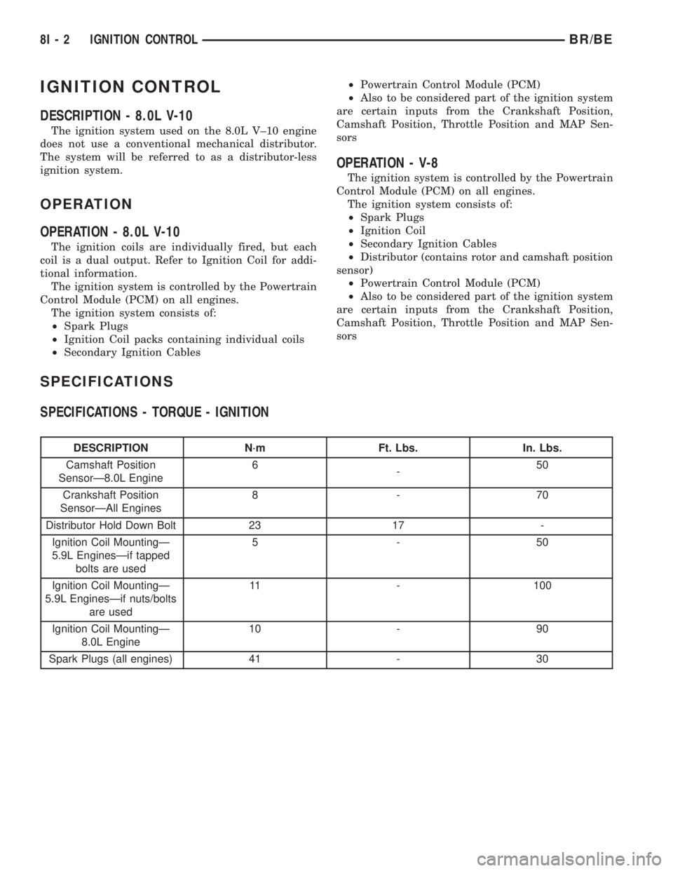
SPECIFICATIONS - TORQUE - IGNITION
DESCRIPTION N´m Ft. Lbs. In. Lbs.
Camshaft Position
SensorÐ8.0L Engine6
-50
Crankshaft Position
SensorÐAll Engines8-70
Distributor Hold Down Bolt 23 17 -
Ignition Coil MountingÐ
5.9L EnginesÐif tapped
bolts are used5-50
Ignition Coil MountingÐ
5.9L EnginesÐif nuts/bolts
are used11 - 100
Ignition Coil MountingÐ
8.0L Engine10 - 90
Spark Plugs (all engines) 41 - 30
8I - 2 IGNITION CONTROLBR/BE
Page 460 of 2255
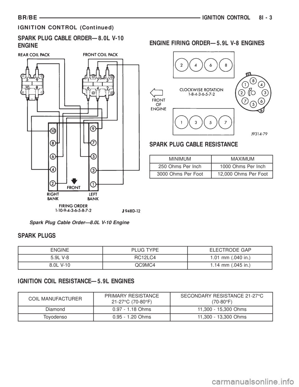
SPARK PLUG CABLE ORDERÐ8.0L V-10
ENGINEENGINE FIRING ORDERÐ5.9L V-8 ENGINES
SPARK PLUG CABLE RESISTANCE
MINIMUM MAXIMUM
250 Ohms Per Inch 1000 Ohms Per Inch
3000 Ohms Per Foot 12,000 Ohms Per Foot
SPARK PLUGS
ENGINE PLUG TYPE ELECTRODE GAP
5.9L V-8 RC12LC4 1.01 mm (.040 in.)
8.0L V-10 QC9MC4 1.14 mm (.045 in.)
IGNITION COIL RESISTANCEÐ5.9L ENGINES
COIL MANUFACTURERPRIMARY RESISTANCE
21-27ÉC (70-80ÉF)SECONDARY RESISTANCE 21-27ÉC
(70-80ÉF)
Diamond 0.97 - 1.18 Ohms 11,300 - 15,300 Ohms
Toyodenso 0.95 - 1.20 Ohms 11,300 - 13,300 Ohms
Spark Plug Cable OrderÐ8.0L V-10 Engine
BR/BEIGNITION CONTROL 8I - 3
IGNITION CONTROL (Continued)