PCM DODGE RAM 2002 Service Repair Manual
[x] Cancel search | Manufacturer: DODGE, Model Year: 2002, Model line: RAM, Model: DODGE RAM 2002Pages: 2255, PDF Size: 62.07 MB
Page 254 of 2255
DIAGNOSIS AND TESTINGÐON-BOARD
DIAGNOSTICS (OBD)
COOLING SYSTEM RELATED DIAGNOSTICS
The powertrain control module (PCM) has been
programmed to monitor certain cooling system com-
ponents:
²If the engine has remained cool for too long a
period, such as with a stuck open thermostat, a Diag-
nostic Trouble Code (DTC) can be set.
²If an open or shorted condition has developed in
the relay circuit controlling the electric radiator fan,
a Diagnostic Trouble Code (DTC) can be set.
If the problem is sensed in a monitored circuit
often enough to indicated an actual problem, a DTC
is stored. The DTC will be stored in the PCM mem-
ory for eventual display to the service technician.
(Refer to 25 - EMISSIONS CONTROL - DESCRIP-
TION).
ACCESSING DIAGNOSTIC TROUBLE CODES
To read DTC's and to obtain cooling system data,
(Refer to 25 - EMISSIONS CONTROL - DESCRIP-
TION).
ERASING TROUBLE CODES
After the problem has been repaired, use the DRB
scan tool to erase a DTC. Refer to the appropriate
Powertrain Diagnostic Procedures service informa-
tion for operation of the DRB scan tool.
DIAGNOSIS AND TESTING - COOLING SYSTEM
LEAKS
ULTRAVIOLET LIGHT METHOD
A leak detection additive is available through the
parts department that can be added to cooling sys-
tem. The additive is highly visible under ultraviolet
light (black light). Pour one ounce of additive into
cooling system. Place heater control unit in HEAT
position. Start and operate engine until radiator
upper hose is warm to touch. Aim the commercially
available black light tool at components to be
checked. If leaks are present, black light will cause
additive to glow a bright green color.
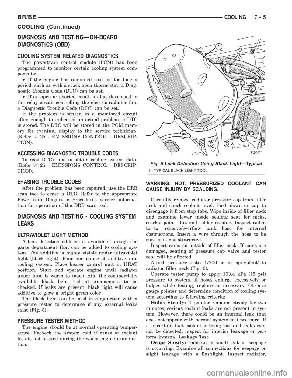
The black light can be used in conjunction with a
pressure tester to determine if any external leaks
exist (Fig. 5).
PRESSURE TESTER METHOD
The engine should be at normal operating temper-
ature. Recheck the system cold if cause of coolant
loss is not located during the warm engine examina-
tion.WARNING: HOT, PRESSURIZED COOLANT CAN
CAUSE INJURY BY SCALDING.
Carefully remove radiator pressure cap from filler
neck and check coolant level. Push down on cap to
disengage it from stop tabs. Wipe inside of filler neck
and examine lower inside sealing seat for nicks,
cracks, paint, dirt and solder residue. Inspect radia-
tor-to- reserve/overflow tank hose for internal
obstructions. Insert a wire through the hose to be
sure it is not obstructed.
Inspect cams on outside of filler neck. If cams are
damaged, seating of pressure cap valve and tester
seal will be affected.
Attach pressure tester (7700 or an equivalent) to
radiator filler neck (Fig. 6).
Operate tester pump to apply 103.4 kPa (15 psi)
pressure to system. If hoses enlarge excessively or
bulges while testing, replace as necessary. Observe
gauge pointer and determine condition of cooling sys-
tem according to following criteria:
Holds Steady:If pointer remains steady for two
minutes, serious coolant leaks are not present in sys-
tem. However, there could be an internal leak that
does not appear with normal system test pressure. If
it is certain that coolant is being lost and leaks can-
not be detected, inspect for interior leakage or per-
form Internal Leakage Test.
Drops Slowly:Indicates a small leak or seepage
is occurring. Examine all connections for seepage or
slight leakage with a flashlight. Inspect radiator,
Fig. 5 Leak Detection Using Black LightÐTypical
1 - TYPICAL BLACK LIGHT TOOL
BR/BECOOLING 7 - 5
COOLING (Continued)
Page 296 of 2255
ENGINE COOLANT TEMP
SENSOR - 5.9L
DESCRIPTION
The Engine Coolant Temperature (ECT) sensor is
used to sense engine coolant temperature. The sensor
protrudes into an engine water jacket.
The ECT sensor is a two-wire Negative Thermal
Coefficient (NTC) sensor. Meaning, as engine coolant
temperature increases, resistance (voltage) in the
sensor decreases. As temperature decreases, resis-
tance (voltage) in the sensor increases.
OPERATION
At key-on, the Powertrain Control Module (PCM)
sends out a regulated 5 volt signal to the ECT sensor.
The PCM then monitors the signal as it passes
through the ECT sensor to the sensor ground (sensor
return).
When the engine is cold, the PCM will operate in
Open Loop cycle. It will demand slightly richer air-
fuel mixtures and higher idle speeds. This is done
until normal operating temperatures are reached.
The PCM uses inputs from the ECT sensor for the
following calculations:
²for engine coolant temperature gauge operation
through CCD or PCI (J1850) communications
²Injector pulse-width
²Spark-advance curves
²ASD relay shut-down times
²Idle Air Control (IAC) motor key-on steps
²Pulse-width prime-shot during cranking
²O2 sensor closed loop times
²Purge solenoid on/off times
²EGR solenoid on/off times (if equipped)
²Leak Detection Pump operation (if equipped)
²Radiator fan relay on/off times (if equipped)²Target idle speed
REMOVAL
WARNING: HOT, PRESSURIZED COOLANT CAN
CAUSE INJURY BY SCALDING. COOLING SYSTEM
MUST BE PARTIALLY DRAINED BEFORE REMOV-
ING THE COOLANT TEMPERATURE SENSOR.
REFER TO GROUP 7, COOLING.
(1) Partially drain cooling system (Refer to 7 -
COOLING - STANDARD PROCEDURE).
(2) Remove air cleaner assembly.
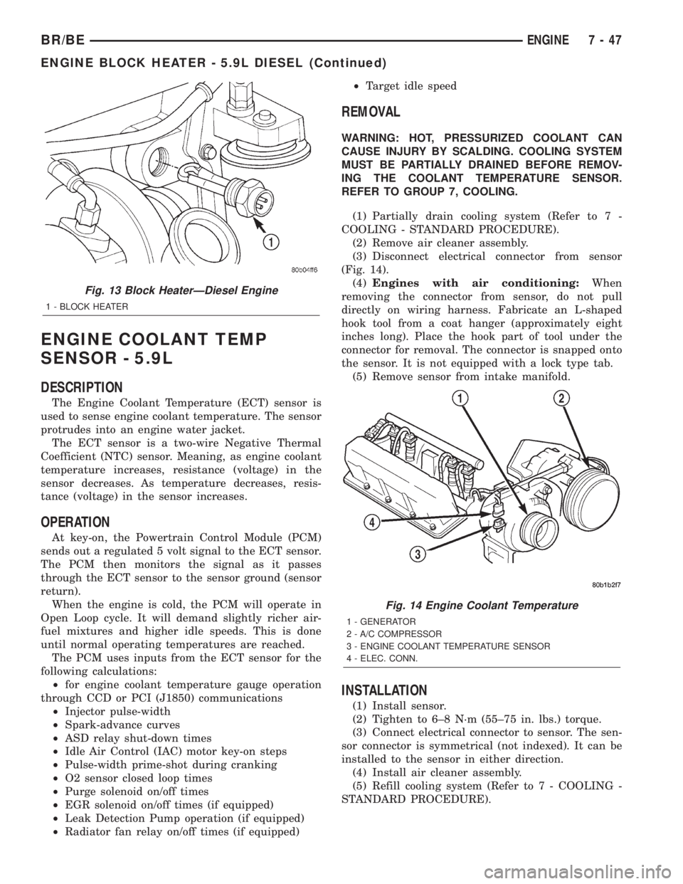
(3) Disconnect electrical connector from sensor
(Fig. 14).
(4)Engines with air conditioning:When
removing the connector from sensor, do not pull
directly on wiring harness. Fabricate an L-shaped
hook tool from a coat hanger (approximately eight
inches long). Place the hook part of tool under the
connector for removal. The connector is snapped onto
the sensor. It is not equipped with a lock type tab.
(5) Remove sensor from intake manifold.
INSTALLATION
(1) Install sensor.
(2) Tighten to 6±8 N´m (55±75 in. lbs.) torque.
(3) Connect electrical connector to sensor. The sen-
sor connector is symmetrical (not indexed). It can be
installed to the sensor in either direction.
(4) Install air cleaner assembly.
(5) Refill cooling system (Refer to 7 - COOLING -
STANDARD PROCEDURE).
Fig. 13 Block HeaterÐDiesel Engine
1 - BLOCK HEATER
Fig. 14 Engine Coolant Temperature
1 - GENERATOR
2 - A/C COMPRESSOR
3 - ENGINE COOLANT TEMPERATURE SENSOR
4 - ELEC. CONN.
BR/BEENGINE 7 - 47
ENGINE BLOCK HEATER - 5.9L DIESEL (Continued)
Page 297 of 2255
ENGINE COOLANT
THERMOSTAT - 5.9L
DESCRIPTION
CAUTION: Do not operate an engine without a ther-
mostat, except for servicing or testing.
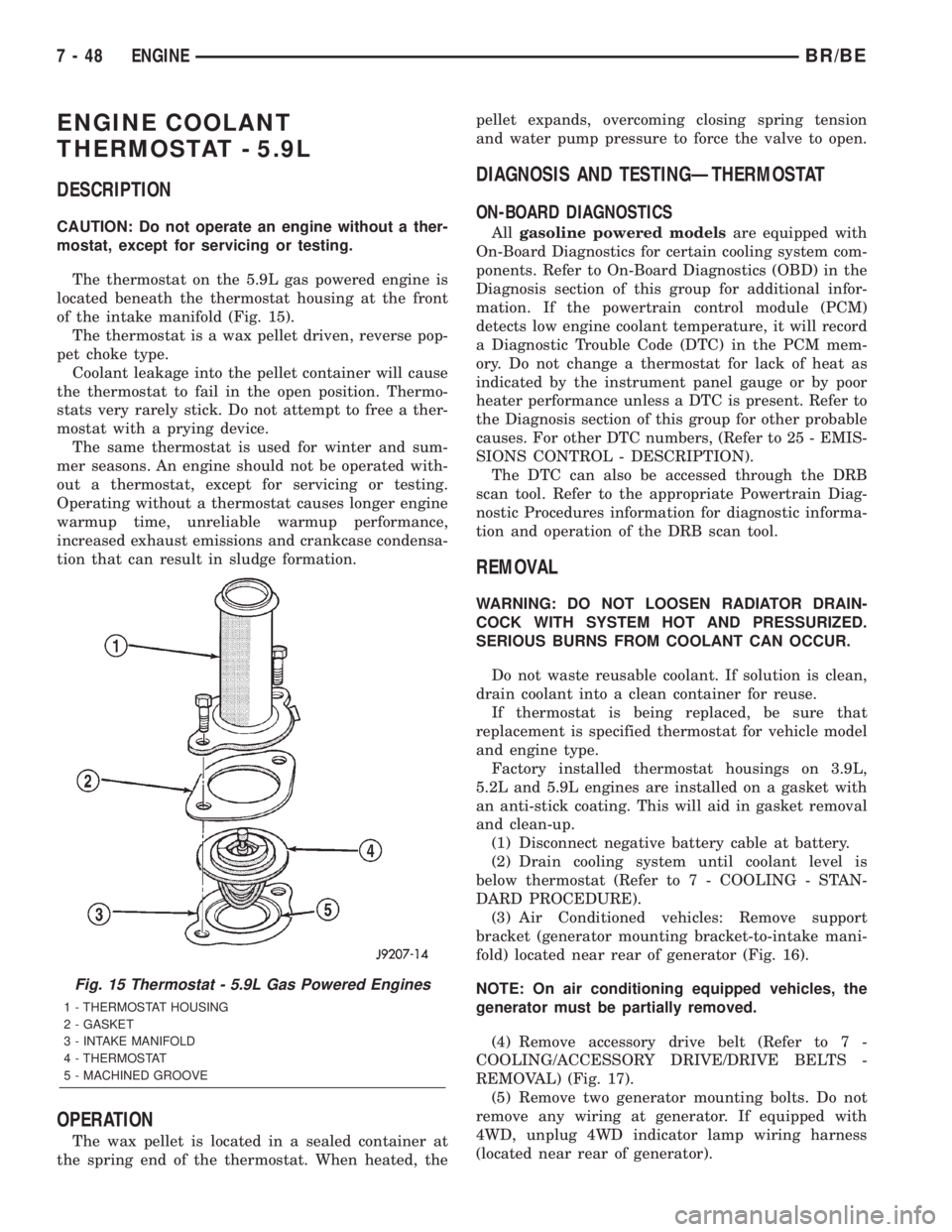
The thermostat on the 5.9L gas powered engine is
located beneath the thermostat housing at the front
of the intake manifold (Fig. 15).
The thermostat is a wax pellet driven, reverse pop-
pet choke type.
Coolant leakage into the pellet container will cause
the thermostat to fail in the open position. Thermo-
stats very rarely stick. Do not attempt to free a ther-
mostat with a prying device.
The same thermostat is used for winter and sum-
mer seasons. An engine should not be operated with-
out a thermostat, except for servicing or testing.
Operating without a thermostat causes longer engine
warmup time, unreliable warmup performance,
increased exhaust emissions and crankcase condensa-
tion that can result in sludge formation.
OPERATION
The wax pellet is located in a sealed container at
the spring end of the thermostat. When heated, thepellet expands, overcoming closing spring tension
and water pump pressure to force the valve to open.
DIAGNOSIS AND TESTINGÐTHERMOSTAT
ON-BOARD DIAGNOSTICS
Allgasoline powered modelsare equipped with
On-Board Diagnostics for certain cooling system com-
ponents. Refer to On-Board Diagnostics (OBD) in the
Diagnosis section of this group for additional infor-
mation. If the powertrain control module (PCM)
detects low engine coolant temperature, it will record
a Diagnostic Trouble Code (DTC) in the PCM mem-
ory. Do not change a thermostat for lack of heat as
indicated by the instrument panel gauge or by poor
heater performance unless a DTC is present. Refer to
the Diagnosis section of this group for other probable
causes. For other DTC numbers, (Refer to 25 - EMIS-
SIONS CONTROL - DESCRIPTION).
The DTC can also be accessed through the DRB
scan tool. Refer to the appropriate Powertrain Diag-
nostic Procedures information for diagnostic informa-
tion and operation of the DRB scan tool.
REMOVAL
WARNING: DO NOT LOOSEN RADIATOR DRAIN-
COCK WITH SYSTEM HOT AND PRESSURIZED.
SERIOUS BURNS FROM COOLANT CAN OCCUR.
Do not waste reusable coolant. If solution is clean,
drain coolant into a clean container for reuse.
If thermostat is being replaced, be sure that
replacement is specified thermostat for vehicle model
and engine type.
Factory installed thermostat housings on 3.9L,
5.2L and 5.9L engines are installed on a gasket with
an anti-stick coating. This will aid in gasket removal
and clean-up.
(1) Disconnect negative battery cable at battery.
(2) Drain cooling system until coolant level is
below thermostat (Refer to 7 - COOLING - STAN-
DARD PROCEDURE).
(3) Air Conditioned vehicles: Remove support
bracket (generator mounting bracket-to-intake mani-
fold) located near rear of generator (Fig. 16).
NOTE: On air conditioning equipped vehicles, the
generator must be partially removed.
(4) Remove accessory drive belt (Refer to 7 -
COOLING/ACCESSORY DRIVE/DRIVE BELTS -
REMOVAL) (Fig. 17).
(5) Remove two generator mounting bolts. Do not
remove any wiring at generator. If equipped with
4WD, unplug 4WD indicator lamp wiring harness
(located near rear of generator).
Fig. 15 Thermostat - 5.9L Gas Powered Engines
1 - THERMOSTAT HOUSING
2 - GASKET
3 - INTAKE MANIFOLD
4 - THERMOSTAT
5 - MACHINED GROOVE
7 - 48 ENGINEBR/BE
Page 300 of 2255
ENGINE COOLANT
THERMOSTAT - 8.0L
DESCRIPTION
CAUTION: Do not operate an engine without a ther-
mostat, except for servicing or testing.
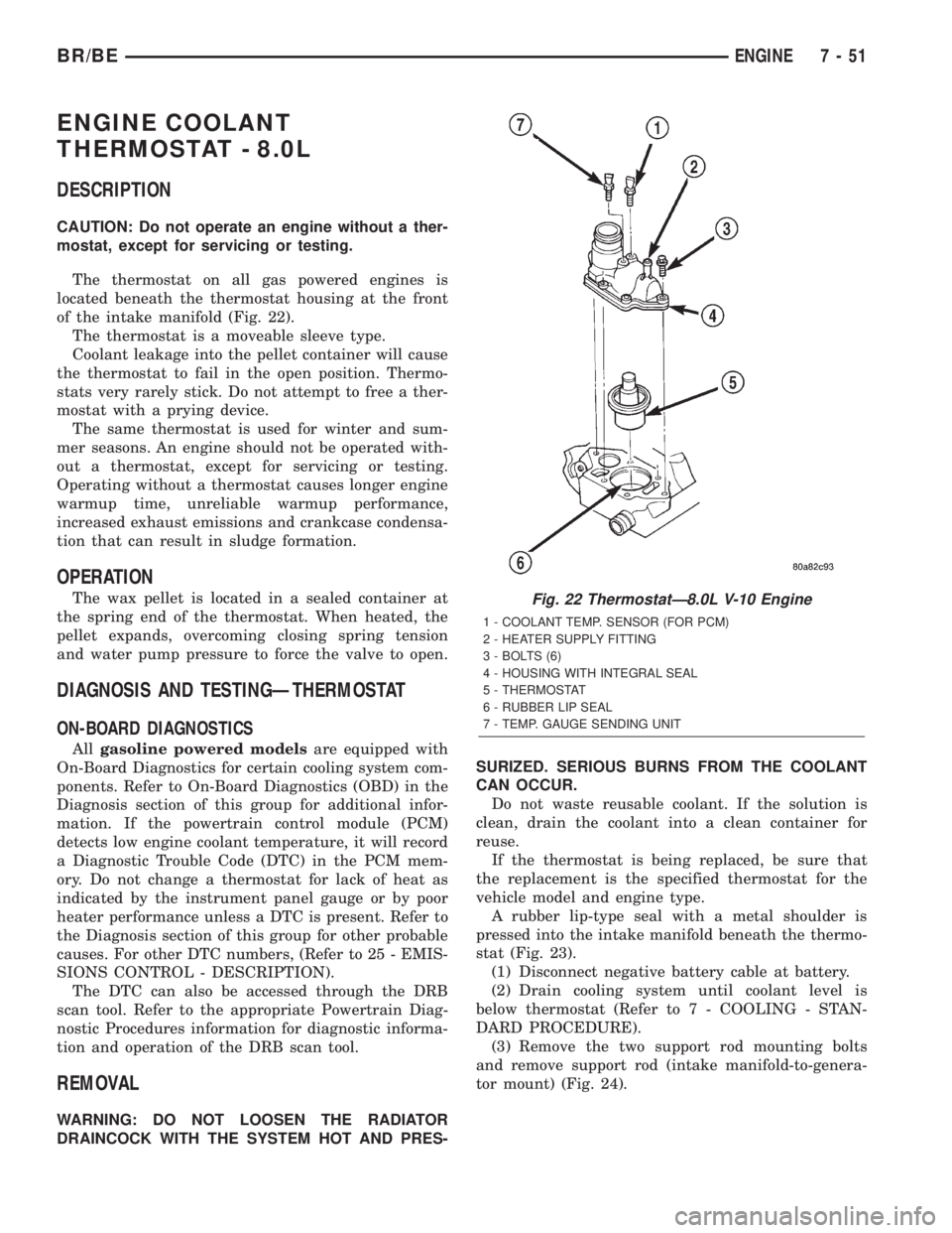
The thermostat on all gas powered engines is
located beneath the thermostat housing at the front
of the intake manifold (Fig. 22).
The thermostat is a moveable sleeve type.
Coolant leakage into the pellet container will cause
the thermostat to fail in the open position. Thermo-
stats very rarely stick. Do not attempt to free a ther-
mostat with a prying device.
The same thermostat is used for winter and sum-
mer seasons. An engine should not be operated with-
out a thermostat, except for servicing or testing.
Operating without a thermostat causes longer engine
warmup time, unreliable warmup performance,
increased exhaust emissions and crankcase condensa-
tion that can result in sludge formation.
OPERATION
The wax pellet is located in a sealed container at
the spring end of the thermostat. When heated, the
pellet expands, overcoming closing spring tension
and water pump pressure to force the valve to open.
DIAGNOSIS AND TESTINGÐTHERMOSTAT
ON-BOARD DIAGNOSTICS
Allgasoline powered modelsare equipped with
On-Board Diagnostics for certain cooling system com-
ponents. Refer to On-Board Diagnostics (OBD) in the
Diagnosis section of this group for additional infor-
mation. If the powertrain control module (PCM)
detects low engine coolant temperature, it will record
a Diagnostic Trouble Code (DTC) in the PCM mem-
ory. Do not change a thermostat for lack of heat as
indicated by the instrument panel gauge or by poor
heater performance unless a DTC is present. Refer to
the Diagnosis section of this group for other probable
causes. For other DTC numbers, (Refer to 25 - EMIS-
SIONS CONTROL - DESCRIPTION).
The DTC can also be accessed through the DRB
scan tool. Refer to the appropriate Powertrain Diag-
nostic Procedures information for diagnostic informa-
tion and operation of the DRB scan tool.
REMOVAL
WARNING: DO NOT LOOSEN THE RADIATOR
DRAINCOCK WITH THE SYSTEM HOT AND PRES-SURIZED. SERIOUS BURNS FROM THE COOLANT
CAN OCCUR.
Do not waste reusable coolant. If the solution is
clean, drain the coolant into a clean container for
reuse.
If the thermostat is being replaced, be sure that
the replacement is the specified thermostat for the
vehicle model and engine type.
A rubber lip-type seal with a metal shoulder is
pressed into the intake manifold beneath the thermo-
stat (Fig. 23).
(1) Disconnect negative battery cable at battery.
(2) Drain cooling system until coolant level is
below thermostat (Refer to 7 - COOLING - STAN-
DARD PROCEDURE).
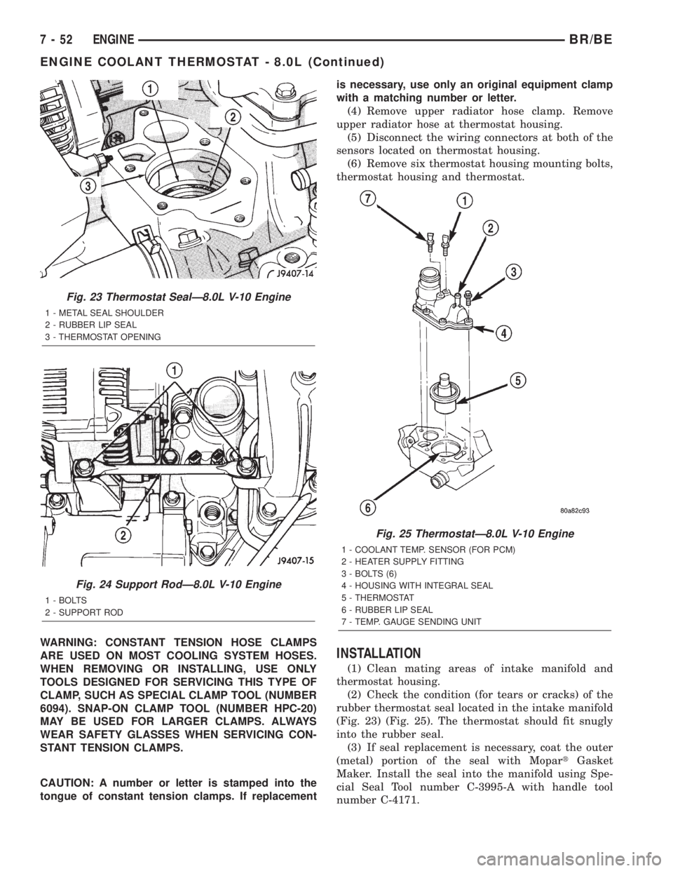
(3) Remove the two support rod mounting bolts
and remove support rod (intake manifold-to-genera-
tor mount) (Fig. 24).
Fig. 22 ThermostatÐ8.0L V-10 Engine
1 - COOLANT TEMP. SENSOR (FOR PCM)
2 - HEATER SUPPLY FITTING
3 - BOLTS (6)
4 - HOUSING WITH INTEGRAL SEAL
5 - THERMOSTAT
6 - RUBBER LIP SEAL
7 - TEMP. GAUGE SENDING UNIT
BR/BEENGINE 7 - 51
Page 301 of 2255
WARNING: CONSTANT TENSION HOSE CLAMPS
ARE USED ON MOST COOLING SYSTEM HOSES.
WHEN REMOVING OR INSTALLING, USE ONLY
TOOLS DESIGNED FOR SERVICING THIS TYPE OF
CLAMP, SUCH AS SPECIAL CLAMP TOOL (NUMBER
6094). SNAP-ON CLAMP TOOL (NUMBER HPC-20)
MAY BE USED FOR LARGER CLAMPS. ALWAYS
WEAR SAFETY GLASSES WHEN SERVICING CON-
STANT TENSION CLAMPS.
CAUTION: A number or letter is stamped into the
tongue of constant tension clamps. If replacementis necessary, use only an original equipment clamp
with a matching number or letter.
(4) Remove upper radiator hose clamp. Remove
upper radiator hose at thermostat housing.
(5) Disconnect the wiring connectors at both of the
sensors located on thermostat housing.
(6) Remove six thermostat housing mounting bolts,
thermostat housing and thermostat.
INSTALLATION
(1) Clean mating areas of intake manifold and
thermostat housing.
(2) Check the condition (for tears or cracks) of the
rubber thermostat seal located in the intake manifold
(Fig. 23) (Fig. 25). The thermostat should fit snugly
into the rubber seal.
(3) If seal replacement is necessary, coat the outer
(metal) portion of the seal with MopartGasket
Maker. Install the seal into the manifold using Spe-
cial Seal Tool number C-3995-A with handle tool
number C-4171.
Fig. 23 Thermostat SealÐ8.0L V-10 Engine
1 - METAL SEAL SHOULDER
2 - RUBBER LIP SEAL
3 - THERMOSTAT OPENING
Fig. 24 Support RodÐ8.0L V-10 Engine
1 - BOLTS
2 - SUPPORT ROD
Fig. 25 ThermostatÐ8.0L V-10 Engine
1 - COOLANT TEMP. SENSOR (FOR PCM)
2 - HEATER SUPPLY FITTING
3 - BOLTS (6)
4 - HOUSING WITH INTEGRAL SEAL
5 - THERMOSTAT
6 - RUBBER LIP SEAL
7 - TEMP. GAUGE SENDING UNIT
7 - 52 ENGINEBR/BE
ENGINE COOLANT THERMOSTAT - 8.0L (Continued)
Page 343 of 2255
assembly. Replace the faulty or damaged antenna
base and cable, if required.
TEST 3
Test 3 checks the condition of the vehicle body
ground connection. This test should be performed
with the battery positive cable removed from the bat-
tery. Disconnect both battery cables, the negative
cable first. Reconnect the battery negative cable and
perform the test as follows:
(1) Connect one ohmmeter test lead to the vehicle
fender. Connect the other test lead to the battery
negative terminal post.
(2) The resistance should be less than one ohm.
(3) If the resistance is more than one ohm, check
the braided ground strap(s) connected to the engine
and the vehicle body for being loose, corroded, or
damaged. Repair the ground strap connections, if
required.
TEST 4
Test 4 checks the condition of the ground between
the antenna base and the vehicle body as follows:
(1) Connect one ohmmeter test lead to the vehicle
fender. Connect the other test lead to the outer crimp
on the antenna coaxial cable connector.
(2) The resistance should be less then one ohm.
(3) If the resistance is more then one ohm, clean
and/or tighten the antenna base to fender mounting
hardware.
REMOVAL
(1) Disconnect and isolate the battery negative
cable.
(2) Reach under the passenger side of the instru-
ment panel near the right cowl side inner panel to
disengage the coaxial cable connector from the
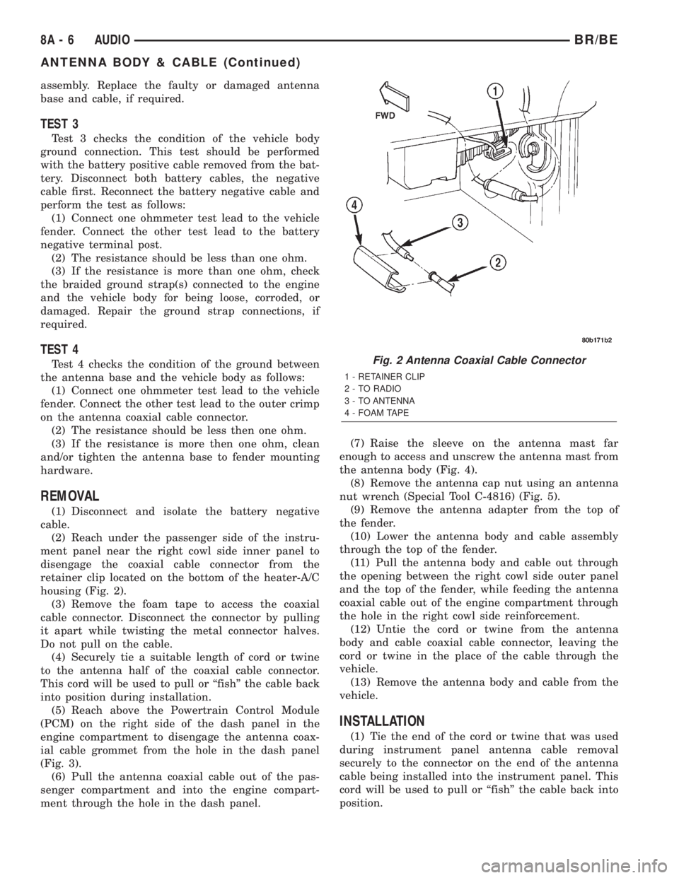
retainer clip located on the bottom of the heater-A/C
housing (Fig. 2).
(3) Remove the foam tape to access the coaxial
cable connector. Disconnect the connector by pulling
it apart while twisting the metal connector halves.
Do not pull on the cable.
(4) Securely tie a suitable length of cord or twine
to the antenna half of the coaxial cable connector.
This cord will be used to pull or ªfishº the cable back
into position during installation.
(5) Reach above the Powertrain Control Module
(PCM) on the right side of the dash panel in the
engine compartment to disengage the antenna coax-
ial cable grommet from the hole in the dash panel
(Fig. 3).
(6) Pull the antenna coaxial cable out of the pas-
senger compartment and into the engine compart-
ment through the hole in the dash panel.(7) Raise the sleeve on the antenna mast far
enough to access and unscrew the antenna mast from
the antenna body (Fig. 4).
(8) Remove the antenna cap nut using an antenna
nut wrench (Special Tool C-4816) (Fig. 5).
(9) Remove the antenna adapter from the top of
the fender.
(10) Lower the antenna body and cable assembly
through the top of the fender.
(11) Pull the antenna body and cable out through
the opening between the right cowl side outer panel
and the top of the fender, while feeding the antenna
coaxial cable out of the engine compartment through
the hole in the right cowl side reinforcement.
(12) Untie the cord or twine from the antenna
body and cable coaxial cable connector, leaving the
cord or twine in the place of the cable through the
vehicle.
(13) Remove the antenna body and cable from the
vehicle.
INSTALLATION
(1) Tie the end of the cord or twine that was used
during instrument panel antenna cable removal
securely to the connector on the end of the antenna
cable being installed into the instrument panel. This
cord will be used to pull or ªfishº the cable back into
position.
Fig. 2 Antenna Coaxial Cable Connector
1 - RETAINER CLIP
2 - TO RADIO
3 - TO ANTENNA
4 - FOAM TAPE
8A - 6 AUDIOBR/BE
ANTENNA BODY & CABLE (Continued)
Page 349 of 2255
RADIO NOISE SUPPRESSION
COMPONENTS
DESCRIPTION
Radio Frequency Interference (RFI) and Electro-
Magnetic Interference (EMI) noise suppression is
accomplished primarily through circuitry internal to
the radio receivers. These internal suppression
devices are only serviced as part of the radio receiver.
External suppression devices that are used on this
vehicle to control RFI or EMI noise include the fol-
lowing:
²Radio antenna base ground
²Radio receiver chassis ground wire or strap
²Engine-to-body ground straps
²Cab-to-bed ground strap
²Heater core ground strap
²Resistor-type spark plugs
²Radio suppression-type secondary ignition wir-
ing.
For more information on the spark plugs and sec-
ondary ignition components, refer to Electrical, Igni-
tion Control.
DIAGNOSIS AND TESTING - RADIO NOISE
SUPPRESSION COMPONENTS
WARNING: ON VEHICLES EQUIPPED WITH AIR-
BAGS, REFER TO ELECTRICAL, RESTRAINTS
BEFORE ATTEMPTING ANY STEERING WHEEL,
STEERING COLUMN, OR INSTRUMENT PANEL
COMPONENT DIAGNOSIS OR SERVICE. FAILURE
TO TAKE THE PROPER PRECAUTIONS COULD
RESULT IN ACCIDENTAL AIRBAG DEPLOYMENT
AND POSSIBLE PERSONAL INJURY.
For complete circuit diagrams, refer to the appro-
priate wiring information. The wiring information
includes wiring diagrams, proper wire and connector
repair procedures, details of wire harness routing
and retention, connector pin-out information and
location views for the various wire harness connec-
tors, splices and grounds. Inspect the ground paths
and connections at the following locations:
²Blower motor
²Cab-to-bed ground strap
²Electric fuel pump
²Engine-to-body ground straps
²Generator
²Ignition module
²Heater core ground strap
²Radio antenna base ground
²Radio receiver chassis ground wire or strap
²Wiper motor.If the source of RFI or EMI noise is identified as a
component on the vehicle (i.e., generator, blower
motor, etc.), the ground path for that component
should be checked. If excessive resistance is found in
any ground circuit, clean, tighten, or repair the
ground circuits or connections to ground as required
before considering any component replacement.
For service and inspection of secondary ignition
components, refer to Electrical, Ignition Control.
Inspect the following secondary ignition system com-
ponents:
²Distributor cap and rotor
²Ignition coil
²Spark plugs
²Spark plug wire routing and condition.
Reroute the spark plug wires or replace the faulty
components as required.
If the source of the RFI or EMI noise is identified
as two-way mobile radio or telephone equipment,
check the equipment installation for the following:
²Power connections should be made directly to
the battery, and fused as closely to the battery as
possible.
²The antenna should be mounted on the roof or
toward the rear of the vehicle. Remember that mag-
netic antenna mounts on the roof panel can adversely
affect the operation of an overhead console compass,
if the vehicle is so equipped.
²The antenna cable should be fully shielded coax-
ial cable, should be as short as is practical, and
should be routed away from the factory-installed
vehicle wire harnesses whenever possible.
²The antenna and cable must be carefully
matched to ensure a low Standing Wave Ratio
(SWR).
Fleet vehicles are available with an extra-cost RFI-
suppressed Powertrain Control Module (PCM). This
unit reduces interference generated by the PCM on
some radio frequencies used in two-way radio com-
munications. However, this unit will not resolve com-
plaints of RFI in the commercial AM or FM radio
frequency ranges.
ENGINE-TO-BODY GROUND
STRAP
REMOVAL
(1) Remove the screw that secures the engine-to-
body ground strap eyelet to the dash panel (Fig. 10).
(2) Remove the screw that secures the engine-to-
body ground strap eyelet to the back of the engine
cylinder head (Fig. 11) or (Fig. 12).
8A - 12 AUDIOBR/BE
Page 366 of 2255
ELECTRONIC CONTROL MODULES
TABLE OF CONTENTS
page page
CENTRAL TIMER MODULE
DESCRIPTION..........................1
OPERATION............................3
DIAGNOSIS AND TESTING - CENTRAL TIMER
MODULE.............................4
REMOVAL.............................5
INSTALLATION..........................6
COMMUNICATION
DESCRIPTION - CCD DATA BUS............6
OPERATION - CCD DATA BUS..............7
DIAGNOSIS AND TESTING - CCD DATA BUS . . 11
CONTROLLER ANTILOCK BRAKE
DESCRIPTION.........................11
OPERATION...........................11
REMOVAL.............................11
INSTALLATION.........................12
DATA LINK CONNECTOR
DESCRIPTION - DATA LINK CONNECTOR....12
OPERATION - DATA LINK CONNECTOR......12
ENGINE CONTROL MODULE
DESCRIPTION - ECM....................13
OPERATION - ECM.....................13
REMOVAL.............................14
INSTALLATION.........................14POWERTRAIN CONTROL MODULE
DESCRIPTION
DESCRIPTION - PCM..................15
DESCRIPTION - MODES OF OPERATION . . . 15
DESCRIPTION - 5 VOLT SUPPLIES.......17
DESCRIPTION - IGNITION CIRCUIT SENSE . 17
DESCRIPTION - POWER GROUNDS......17
DESCRIPTION - SENSOR RETURN.......17
DESCRIPTION - SIGNAL GROUND........17
OPERATION
OPERATION - PCM - GAS ENGINES.......18
OPERATION - DIESEL..................18
OPERATION - 5 VOLT SUPPLIES.........19
OPERATION - IGNITION CIRCUIT SENSE . . . 19
REMOVAL.............................19
INSTALLATION.........................20
HEATED SEAT MODULE
DESCRIPTION.........................20
OPERATION...........................20
DIAGNOSIS AND TESTING - HEATED SEAT
MODULE............................21
REMOVAL.............................23
INSTALLATION.........................23
CENTRAL TIMER MODULE
DESCRIPTION
Three versions of the Central Timer Module (CTM)
are available on this vehicle, a base version (Fig. 1),
a high-line version (Fig. 2), and a premium version.
Whichever version of the CTM the vehicle is
equipped with, it is concealed under the driver side
end of the instrument panel inboard of the instru-
ment panel steering column opening, where it is
secured to a stamped steel bracket that is integral to
the instrument panel armature. The CTM is enclosed
in a molded plastic housing with one (base) or two
(high-line/premium) integral external connector
receptacles that connect it to the vehicle electrical
system through one (base) or two (high-line/pre-
mium) take outs with connectors from the instru-
ment panel wire harness.
The base version of the CTM is used on base mod-
els of this vehicle. It is also sometimes referred to as
the Integrated Electronic Module (IEM). The base
version of the CTM combines the functions of achime module and an intermittent wipe module in a
single unit. The high-line version of the CTM is used
on high-line vehicles. The high-line CTM provides all
of the functions of the base version of the CTM, but
also is used to control and integrate many additional
electronic functions and features included on high-
line models. The premium version of the CTM is the
same as the high-line version, but is used only on
models equipped with the heated seat option.
The high-line and premium versions of the CTM
utilize integrated circuitry and information carried
on the Chrysler Collision Detection (CCD) data bus
network along with many hard wired inputs to mon-
itor many sensor and switch inputs throughout the
vehicle. In response to those inputs, the internal cir-
cuitry and programming of the CTM allow it to con-
trol and integrate many electronic functions and
features of the vehicle through both hard wired out-
puts and the transmission of electronic message out-
puts to other electronic modules in the vehicle over
the CCD data bus.
BR/BEELECTRONIC CONTROL MODULES 8E - 1
Page 369 of 2255
HARD WIRED OUTPUTS
The hard wired outputs of the CTM include the fol-
lowing:
²CCD bus± - high-line/premium version only
²CCD bus+ - high-line/premium version only
²Courtesy lamp switch output - high-line/pre-
mium version only
²Door lock driver - high-line/premium version
only
²Door unlock driver - high-line/premium version
only
²Headlamp relay control - high-line/premium ver-
sion only
²Heated seat relay control - premium version
only
²Horn relay control - high-line/premium version
only
²VTSS indicator driver - high-line/premium ver-
sion only
²Wiper motor relay control
MESSAGING
The high-line/premium CTM uses the following
messages received from other electronic modules over
the CCD data bus:
²Airbag Deploy (ACM)
²Charging System Failure (PCM)
²Engine RPM (PCM)
²System Voltage (PCM)
²Vehicle Speed (PCM)
²Voltage Fault (PCM)
The high-line/premium CTM provides the following
messages to other electronic modules over the CCD
data bus:
²Engine Enable (PCM)
²Radio Seek Up (Radio)
²Radio Seek Down (Radio)
²Radio Volume Up (Radio)
²Radio Volume Down (Radio)
²Preset Scan (Radio)
DIAGNOSIS AND TESTING - CENTRAL TIMER
MODULE
The hard wired inputs to and outputs from the
Central Timer Module (CTM) may be diagnosed and
tested using conventional diagnostic tools and meth-
ods. Refer to the appropriate wiring information. The
wiring information includes wiring diagrams, proper
wire and connector repair procedures, further details
on wire harness routing and retention, as well as
pin-out and location views for the various wire har-
ness connectors, splices and grounds.
However, conventional diagnostic methods may not
prove conclusive in the diagnosis of the high-line/pre-
mium CTM. In order to obtain conclusive testing of
the high-line/premium CTM, the Chrysler CollisionDetection (CCD) data bus network and all of the elec-
tronic modules that provide inputs to or receive out-
puts from the CTM must also be checked. The most
reliable, efficient, and accurate means to diagnose
the high-line/premium CTM, the CCD data bus net-
work, and the electronic modules that provide inputs
to or receive outputs from the high-line/premium
CTM requires the use of a DRBIIItscan tool and the
appropriate diagnostic information. The DRBIIIt
scan tool can provide confirmation that the CCD data
bus network is functional, that all of the electronic
modules are sending and receiving the proper mes-
sages over the CCD data bus, and that the CTM is
receiving the proper hard wired inputs and respond-
ing with the proper hard wired outputs needed to
perform its many functions.
WARNING: ON VEHICLES EQUIPPED WITH AIR-
BAGS, DISABLE THE AIRBAG SYSTEM BEFORE
ATTEMPTING ANY STEERING WHEEL, STEERING
COLUMN, OR INSTRUMENT PANEL COMPONENT
DIAGNOSIS OR SERVICE. DISCONNECT AND ISO-
LATE THE BATTERY NEGATIVE (GROUND) CABLE,
THEN WAIT TWO MINUTES FOR THE AIRBAG SYS-
TEM CAPACITOR TO DISCHARGE BEFORE PER-
FORMING FURTHER DIAGNOSIS OR SERVICE. THIS
IS THE ONLY SURE WAY TO DISABLE THE AIRBAG
SYSTEM. FAILURE TO TAKE THE PROPER PRE-
CAUTIONS COULD RESULT IN ACCIDENTAL AIR-
BAG DEPLOYMENT AND POSSIBLE PERSONAL
INJURY.
NOTE: The following tests may not prove conclu-
sive in the diagnosis of the high-line or premium
versions of the Central Timer Module (CTM). The
most reliable, efficient, and accurate means to diag-
nose the high-line or premium CTM requires the
use of a DRBIIITscan tool and the appropriate diag-
nostic information.
(1) Check the fused B(+) fuse (Fuse 13 - 10
ampere) in the Junction Block (JB). If OK, go to Step
2. If not OK, repair the shorted circuit or component
as required and replace the faulty fuse.
(2) Check for battery voltage at the fused B(+) fuse
(Fuse 13 - 10 ampere) in the JB. If OK, go to Step 3.
If not OK, repair the open fused B(+) circuit between
the JB and the Power Distribution Center (PDC) as
required.
(3) For a base version CTM, check the fused igni-
tion switch output (st-run) fuse (Fuse 11 - 10 ampere)
in the JB. For a high-line/premium version CTM,
check the fused ignition switch output (run-acc) fuse
(Fuse6-25ampere) in the JB. If OK, go to Step 4. If
not OK, repair the shorted circuit or component as
required and replace the faulty fuse.
8E - 4 ELECTRONIC CONTROL MODULESBR/BE
CENTRAL TIMER MODULE (Continued)
Page 377 of 2255
(2) Push the harness connector locks to release the
locks, (Fig. 11) then remove the connectors from the
CAB.
(3) Disconnect the pump motor connector (Fig. 12)
.
(4) Remove screws attaching CAB to the HCU
(Fig. 13) .
(5) Remove the CAB.
INSTALLATION
(1) Place the CAB onto the HCU.
NOTE: Insure the CAB seal is in position before
installation.
(2) Install the mounting screws and tighten to
4-4.7 N´m (36-42 in. lbs.).
(3) Connect the pump motor harness.
(4) Connect the harnesses to the CAB and lock the
connectors.
(5) Connect battery.
DATA LINK CONNECTOR
DESCRIPTION - DATA LINK CONNECTOR
The data link connector (DLC) is located at the
lower edge of the instrument panel near the steering
column.
OPERATION - DATA LINK CONNECTOR
The 16±way data link connector (diagnostic scan
tool connector) links the Diagnostic Readout Box
(DRB) scan tool or the Mopar Diagnostic System
(MDS) with the Powertrain Control Module (PCM).
Fig. 11 Harness Connector Locks
1 - CONNECTOR LOCK
2 - CAB
Fig. 12 Pump
1 - PUMP MOTOR
2 - PUMP CONNECTOR
Fig. 13 Controller Mounting Screws
1 - CAB
2 - MOUNTING LOCATIONS
8E - 12 ELECTRONIC CONTROL MODULESBR/BE
CONTROLLER ANTILOCK BRAKE (Continued)