DODGE RAM 2003 Service Repair Manual
Manufacturer: DODGE, Model Year: 2003, Model line: RAM, Model: DODGE RAM 2003Pages: 2895, PDF Size: 83.15 MB
Page 1671 of 2895
(1) Disconnect the battery negative cables.
(2) Discharge the A/C system (Refer to 24 - HEAT-
ING & AIR CONDITIONING/PLUMBING - STAN-
DARD PROCEDURE) and remove the A/C condenser
(Refer to 24 - HEATING & AIR CONDITIONING/
PLUMBING/A/C CONDENSER - REMOVAL) (if A/C
equipped).
(3) Remove the transmission auxiliary cooler
(Refer to 7 - COOLING/TRANSMISSION/TRANS
COOLER - REMOVAL).
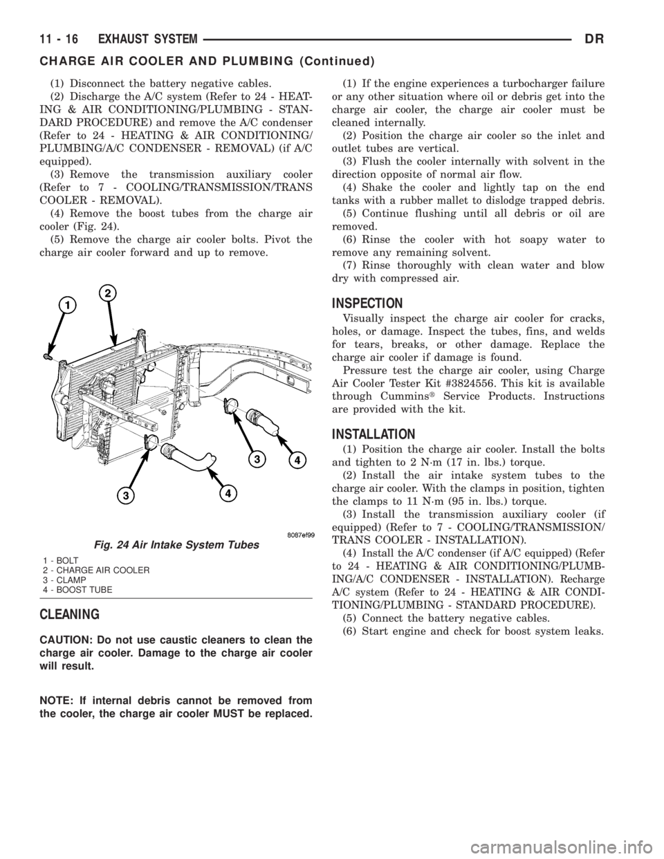
(4) Remove the boost tubes from the charge air
cooler (Fig. 24).
(5) Remove the charge air cooler bolts. Pivot the
charge air cooler forward and up to remove.
CLEANING
CAUTION: Do not use caustic cleaners to clean the
charge air cooler. Damage to the charge air cooler
will result.
NOTE: If internal debris cannot be removed from
the cooler, the charge air cooler MUST be replaced.(1) If the engine experiences a turbocharger failure
or any other situation where oil or debris get into the
charge air cooler, the charge air cooler must be
cleaned internally.
(2) Position the charge air cooler so the inlet and
outlet tubes are vertical.
(3) Flush the cooler internally with solvent in the
direction opposite of normal air flow.
(4)
Shake the cooler and lightly tap on the end
tanks with a rubber mallet to dislodge trapped debris.
(5) Continue flushing until all debris or oil are
removed.
(6) Rinse the cooler with hot soapy water to
remove any remaining solvent.
(7) Rinse thoroughly with clean water and blow
dry with compressed air.
INSPECTION
Visually inspect the charge air cooler for cracks,
holes, or damage. Inspect the tubes, fins, and welds
for tears, breaks, or other damage. Replace the
charge air cooler if damage is found.
Pressure test the charge air cooler, using Charge
Air Cooler Tester Kit #3824556. This kit is available
through CumminstService Products. Instructions
are provided with the kit.
INSTALLATION
(1) Position the charge air cooler. Install the bolts
and tighten to 2 N´m (17 in. lbs.) torque.
(2) Install the air intake system tubes to the
charge air cooler. With the clamps in position, tighten
the clamps to 11 N´m (95 in. lbs.) torque.
(3) Install the transmission auxiliary cooler (if
equipped) (Refer to 7 - COOLING/TRANSMISSION/
TRANS COOLER - INSTALLATION).
(4)
Install the A/C condenser (if A/C equipped) (Refer
to 24 - HEATING & AIR CONDITIONING/PLUMB-
ING/A/C CONDENSER - INSTALLATION). Recharge
A/C system (Refer to 24 - HEATING & AIR CONDI-
TIONING/PLUMBING - STANDARD PROCEDURE).
(5) Connect the battery negative cables.
(6) Start engine and check for boost system leaks.
Fig. 24 Air Intake System Tubes
1 - BOLT
2 - CHARGE AIR COOLER
3 - CLAMP
4 - BOOST TUBE
11 - 16 EXHAUST SYSTEMDR
CHARGE AIR COOLER AND PLUMBING (Continued)
Page 1672 of 2895
FRAMES & BUMPERS
TABLE OF CONTENTS
page page
BUMPERS
SPECIFICATIONS - TORQUE...............1
FRONT AIR DAM
REMOVAL.............................2
INSTALLATION..........................2
FRONT BUMPER
REMOVAL.............................2
INSTALLATION..........................2
FRONT FASCIA
REMOVAL.............................3
INSTALLATION..........................3
REAR BUMPER
REMOVAL.............................4
INSTALLATION..........................4
FRAME
STANDARD PROCEDURE
STANDARD PROCEDURE - LIGHT DUTY
FRONT FRAME RAIL TIP REPLACEMENT....4
STANDARD PROCEDURE - HYDROFORM
FENDER RAIL REPAIR.................12
STANDARD PROCEDURE - REAR FRAME
H-SECTION REPLACEMENT.............15SPECIFICATIONS
SPECIFICATIONS - FRAME DIMENSIONS . . . 17
SPECIFICATIONS - TORQUE............23
FRONT CROSSMEMBER
REMOVAL.............................23
INSTALLATION.........................23
FRONT SKID PLATE
REMOVAL.............................24
INSTALLATION.........................24
TRANSMISSION CROSSMEMBER
REMOVAL.............................24
INSTALLATION.........................25
TRAILER HITCH
REMOVAL.............................25
INSTALLATION.........................25
TRANSFER CASE SKID PLATE
REMOVAL.............................26
INSTALLATION.........................26
FRONT TOW HOOK ASSEMBLY
REMOVAL.............................26
INSTALLATION.........................26
BUMPERS
SPECIFICATIONS - TORQUE
TORQUE SPECIFICATIONS
DESCRIPTION N´m Ft. Lbs. In. Lbs.
Front bumper center bracket nuts 95 70 Ð
Front bumper stud plate nuts 95 70 Ð
License plate hitch reinforcement bolts 54 40 Ð
Rear bumper support bracket stud plate nuts 54 40 Ð
Rear bumper support bracket to hitch bolts 54 40 Ð
Rear bumper to hitch bolts 54 40 Ð
DRFRAMES & BUMPERS 13 - 1
Page 1673 of 2895
FRONT AIR DAM
REMOVAL
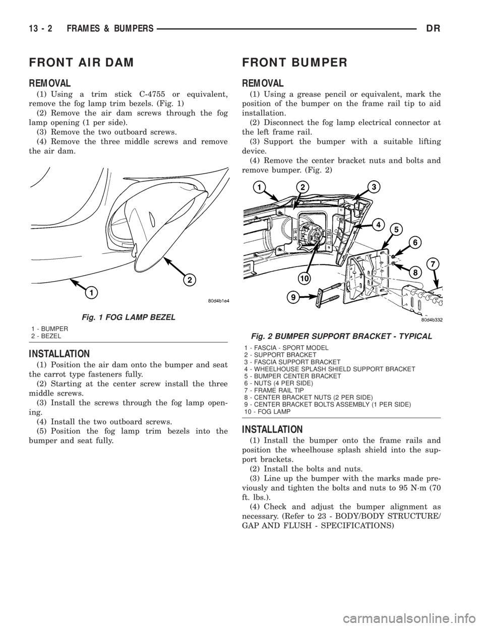
(1) Using a trim stick C-4755 or equivalent,
remove the fog lamp trim bezels. (Fig. 1)
(2) Remove the air dam screws through the fog
lamp opening (1 per side).
(3) Remove the two outboard screws.
(4) Remove the three middle screws and remove
the air dam.
INSTALLATION
(1) Position the air dam onto the bumper and seat
the carrot type fasteners fully.
(2) Starting at the center screw install the three
middle screws.
(3) Install the screws through the fog lamp open-
ing.
(4) Install the two outboard screws.
(5) Position the fog lamp trim bezels into the
bumper and seat fully.
FRONT BUMPER
REMOVAL
(1) Using a grease pencil or equivalent, mark the
position of the bumper on the frame rail tip to aid
installation.
(2) Disconnect the fog lamp electrical connector at
the left frame rail.
(3) Support the bumper with a suitable lifting
device.
(4) Remove the center bracket nuts and bolts and
remove bumper. (Fig. 2)
INSTALLATION
(1) Install the bumper onto the frame rails and
position the wheelhouse splash shield into the sup-
port brackets.
(2) Install the bolts and nuts.
(3) Line up the bumper with the marks made pre-
viously and tighten the bolts and nuts to 95 N´m (70
ft. lbs.).
(4) Check and adjust the bumper alignment as
necessary. (Refer to 23 - BODY/BODY STRUCTURE/
GAP AND FLUSH - SPECIFICATIONS)
Fig. 1 FOG LAMP BEZEL
1 - BUMPER
2 - BEZEL
Fig. 2 BUMPER SUPPORT BRACKET - TYPICAL
1 - FASCIA - SPORT MODEL
2 - SUPPORT BRACKET
3 - FASCIA SUPPORT BRACKET
4 - WHEELHOUSE SPLASH SHIELD SUPPORT BRACKET
5 - BUMPER CENTER BRACKET
6 - NUTS (4 PER SIDE)
7 - FRAME RAIL TIP
8 - CENTER BRACKET NUTS (2 PER SIDE)
9 - CENTER BRACKET BOLTS ASSEMBLY (1 PER SIDE)
10 - FOG LAMP
13 - 2 FRAMES & BUMPERSDR
Page 1674 of 2895
FRONT FASCIA
REMOVAL
ST/SLT/SLT+ - FASCIA REMOVAL
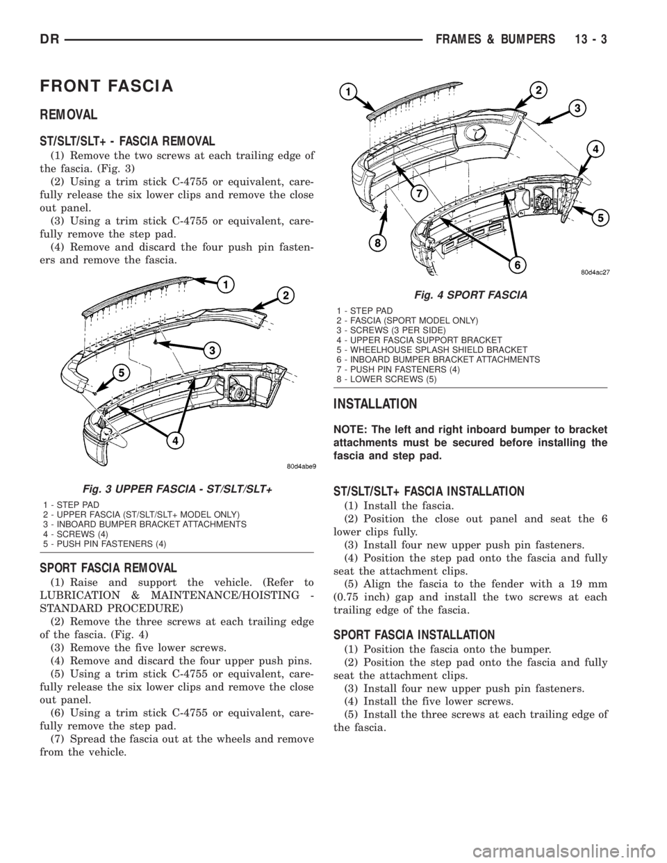
(1) Remove the two screws at each trailing edge of
the fascia. (Fig. 3)
(2) Using a trim stick C-4755 or equivalent, care-
fully release the six lower clips and remove the close
out panel.
(3) Using a trim stick C-4755 or equivalent, care-
fully remove the step pad.
(4) Remove and discard the four push pin fasten-
ers and remove the fascia.
SPORT FASCIA REMOVAL
(1) Raise and support the vehicle. (Refer to
LUBRICATION & MAINTENANCE/HOISTING -
STANDARD PROCEDURE)
(2) Remove the three screws at each trailing edge
of the fascia. (Fig. 4)
(3) Remove the five lower screws.
(4) Remove and discard the four upper push pins.
(5) Using a trim stick C-4755 or equivalent, care-
fully release the six lower clips and remove the close
out panel.
(6) Using a trim stick C-4755 or equivalent, care-
fully remove the step pad.
(7) Spread the fascia out at the wheels and remove
from the vehicle.
INSTALLATION
NOTE: The left and right inboard bumper to bracket
attachments must be secured before installing the
fascia and step pad.
ST/SLT/SLT+ FASCIA INSTALLATION
(1) Install the fascia.
(2) Position the close out panel and seat the 6
lower clips fully.
(3) Install four new upper push pin fasteners.
(4) Position the step pad onto the fascia and fully
seat the attachment clips.
(5) Align the fascia to the fender with a 19 mm
(0.75 inch) gap and install the two screws at each
trailing edge of the fascia.
SPORT FASCIA INSTALLATION
(1) Position the fascia onto the bumper.
(2) Position the step pad onto the fascia and fully
seat the attachment clips.
(3) Install four new upper push pin fasteners.
(4) Install the five lower screws.
(5) Install the three screws at each trailing edge of
the fascia.
Fig. 3 UPPER FASCIA - ST/SLT/SLT+
1 - STEP PAD
2 - UPPER FASCIA (ST/SLT/SLT+ MODEL ONLY)
3 - INBOARD BUMPER BRACKET ATTACHMENTS
4 - SCREWS (4)
5 - PUSH PIN FASTENERS (4)
Fig. 4 SPORT FASCIA
1 - STEP PAD
2 - FASCIA (SPORT MODEL ONLY)
3 - SCREWS (3 PER SIDE)
4 - UPPER FASCIA SUPPORT BRACKET
5 - WHEELHOUSE SPLASH SHIELD BRACKET
6 - INBOARD BUMPER BRACKET ATTACHMENTS
7 - PUSH PIN FASTENERS (4)
8 - LOWER SCREWS (5)
DRFRAMES & BUMPERS 13 - 3
Page 1675 of 2895
REAR BUMPER
REMOVAL
(1) Raise and support the vehicle. (Refer to
LUBRICATION & MAINTENANCE/HOISTING -
STANDARD PROCEDURE)
(2) Remove the license plate.
(3) Remove the bolts behind the plate.
(4) Disconnect the license plate light electrical con-
nectors.
(5) Disconnect the trailer light connector electrical
connection, if equipped.
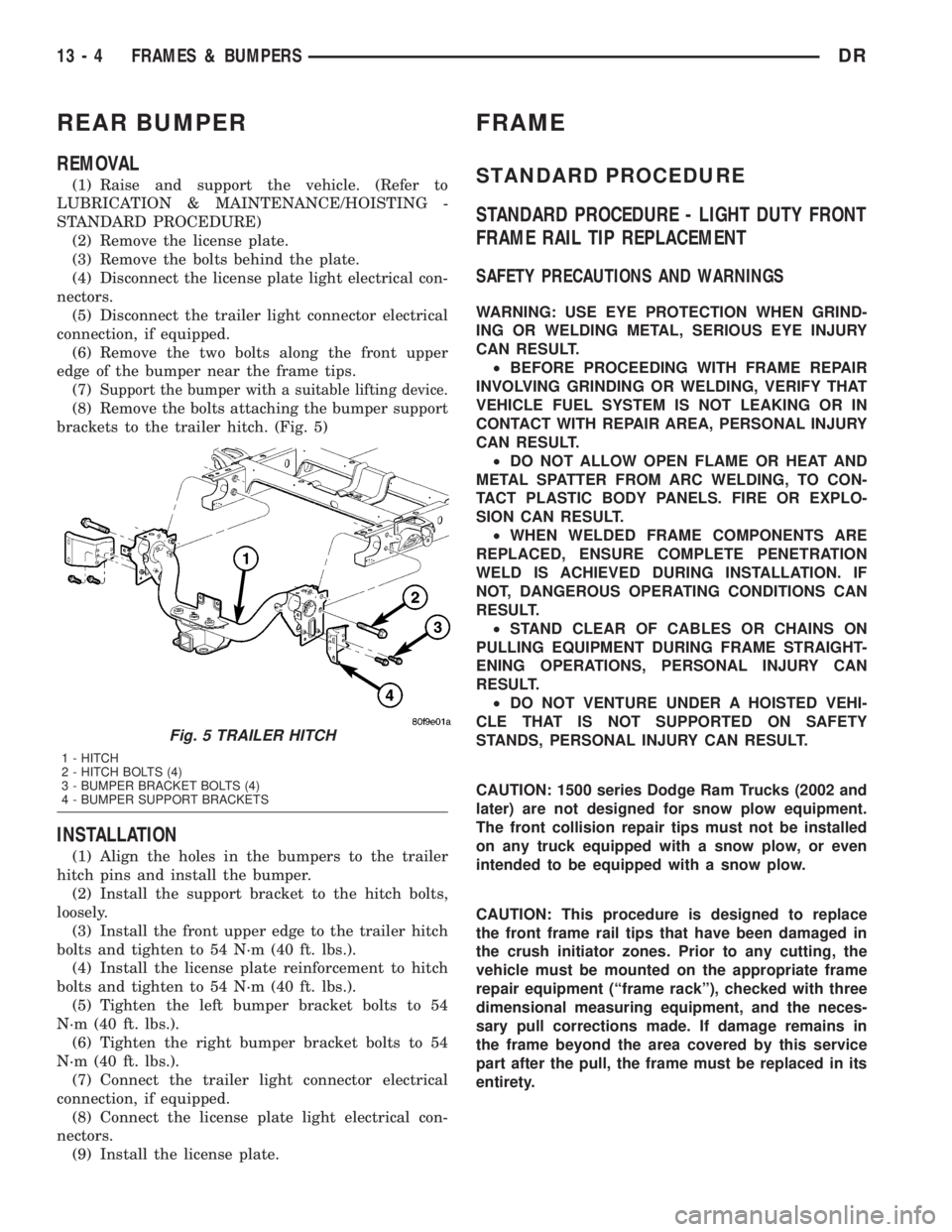
(6) Remove the two bolts along the front upper
edge of the bumper near the frame tips.
(7)
Support the bumper with a suitable lifting device.
(8) Remove the bolts attaching the bumper support
brackets to the trailer hitch. (Fig. 5)
INSTALLATION
(1) Align the holes in the bumpers to the trailer
hitch pins and install the bumper.
(2) Install the support bracket to the hitch bolts,
loosely.
(3) Install the front upper edge to the trailer hitch
bolts and tighten to 54 N´m (40 ft. lbs.).
(4) Install the license plate reinforcement to hitch
bolts and tighten to 54 N´m (40 ft. lbs.).
(5) Tighten the left bumper bracket bolts to 54
N´m (40 ft. lbs.).
(6) Tighten the right bumper bracket bolts to 54
N´m (40 ft. lbs.).
(7) Connect the trailer light connector electrical
connection, if equipped.
(8) Connect the license plate light electrical con-
nectors.
(9) Install the license plate.
FRAME
STANDARD PROCEDURE
STANDARD PROCEDURE - LIGHT DUTY FRONT
FRAME RAIL TIP REPLACEMENT
SAFETY PRECAUTIONS AND WARNINGS
WARNING: USE EYE PROTECTION WHEN GRIND-
ING OR WELDING METAL, SERIOUS EYE INJURY
CAN RESULT.
²BEFORE PROCEEDING WITH FRAME REPAIR
INVOLVING GRINDING OR WELDING, VERIFY THAT
VEHICLE FUEL SYSTEM IS NOT LEAKING OR IN
CONTACT WITH REPAIR AREA, PERSONAL INJURY
CAN RESULT.
²DO NOT ALLOW OPEN FLAME OR HEAT AND
METAL SPATTER FROM ARC WELDING, TO CON-
TACT PLASTIC BODY PANELS. FIRE OR EXPLO-
SION CAN RESULT.
²WHEN WELDED FRAME COMPONENTS ARE
REPLACED, ENSURE COMPLETE PENETRATION
WELD IS ACHIEVED DURING INSTALLATION. IF
NOT, DANGEROUS OPERATING CONDITIONS CAN
RESULT.
²STAND CLEAR OF CABLES OR CHAINS ON
PULLING EQUIPMENT DURING FRAME STRAIGHT-
ENING OPERATIONS, PERSONAL INJURY CAN
RESULT.
²DO NOT VENTURE UNDER A HOISTED VEHI-
CLE THAT IS NOT SUPPORTED ON SAFETY
STANDS, PERSONAL INJURY CAN RESULT.
CAUTION: 1500 series Dodge Ram Trucks (2002 and
later) are not designed for snow plow equipment.
The front collision repair tips must not be installed
on any truck equipped with a snow plow, or even
intended to be equipped with a snow plow.
CAUTION: This procedure is designed to replace
the front frame rail tips that have been damaged in
the crush initiator zones. Prior to any cutting, the
vehicle must be mounted on the appropriate frame
repair equipment (ªframe rackº), checked with three
dimensional measuring equipment, and the neces-
sary pull corrections made. If damage remains in
the frame beyond the area covered by this service
part after the pull, the frame must be replaced in its
entirety.
Fig. 5 TRAILER HITCH
1 - HITCH
2 - HITCH BOLTS (4)
3 - BUMPER BRACKET BOLTS (4)
4 - BUMPER SUPPORT BRACKETS
13 - 4 FRAMES & BUMPERSDR
Page 1676 of 2895
CAUTION: Do not reuse damaged fasteners, quality
of repair would be suspect. Failure to use only pro-
duction fasteners or fasteners of equivalent hard-
ness can result in loosening or failure. Do not drill
any holes in the frame that are not specifically out-
lined in this or other, DaimlerChrysler procedure as
frame rail failure can result. When using heat to
straighten frame components do not exceed 566ÉC
(1050ÉF), metal fatigue can result.
NOTE: Procedures for 4X2 and 4X4 are common
except as noted in this procedure.
(1) Disconnect and isolate the battery negative
cable.
(2) Remove the front wheelhouse splash shield.
(Refer to 23 - BODY/EXTERIOR/FRONT WHEEL-
HOUSE SPLASH SHIELD - REMOVAL)
(3) Remove the bolts and position aside the wire
harness and grounds, if required.
(4) Remove the front bumper. (Refer to 13 -
FRAME & BUMPERS/BUMPERS/FRONT BUMPER
- REMOVAL)
(5) Loosen and lower the stabilizer bar mount and
bar. (Refer to 2 - SUSPENSION/FRONT/STABI-
LIZER BAR - REMOVAL)
(6) Remove the front cab mount bolt to the Front
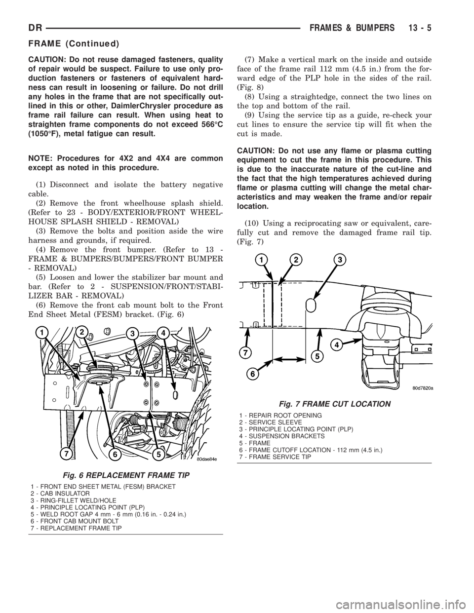
End Sheet Metal (FESM) bracket. (Fig. 6)(7) Make a vertical mark on the inside and outside
face of the frame rail 112 mm (4.5 in.) from the for-
ward edge of the PLP hole in the sides of the rail.
(Fig. 8)
(8) Using a straightedge, connect the two lines on
the top and bottom of the rail.
(9) Using the service tip as a guide, re-check your
cut lines to ensure the service tip will fit when the
cut is made.
CAUTION: Do not use any flame or plasma cutting
equipment to cut the frame in this procedure. This
is due to the inaccurate nature of the cut-line and
the fact that the high temperatures achieved during
flame or plasma cutting will change the metal char-
acteristics and may weaken the frame and/or repair
location.
(10) Using a reciprocating saw or equivalent, care-
fully cut and remove the damaged frame rail tip.
(Fig. 7)
Fig. 6 REPLACEMENT FRAME TIP
1 - FRONT END SHEET METAL (FESM) BRACKET
2 - CAB INSULATOR
3 - RING-FILLET WELD/HOLE
4 - PRINCIPLE LOCATING POINT (PLP)
5 - WELD ROOT GAP 4 mm-6mm(0.16 in. - 0.24 in.)
6 - FRONT CAB MOUNT BOLT
7 - REPLACEMENT FRAME TIP
Fig. 7 FRAME CUT LOCATION
1 - REPAIR ROOT OPENING
2 - SERVICE SLEEVE
3 - PRINCIPLE LOCATING POINT (PLP)
4 - SUSPENSION BRACKETS
5 - FRAME
6 - FRAME CUTOFF LOCATION - 112 mm (4.5 in.)
7 - FRAME SERVICE TIP
DRFRAMES & BUMPERS 13 - 5
FRAME (Continued)
Page 1677 of 2895
(11) Assemble the service sleeve. Refer to SER-
VICE SLEEVE ASSEMBLY at the end of this proce-
dure.
NOTE: Any burned surface coatings will need to be
removed from the sleeve prior to installation and
application of corrosion preventative coatings.
(12) Smooth and square the cut edges of the origi-
nal frame. (Fig. 7)
(13) Dress the cut edge of the existing frame in
preparation for the new rail tip.
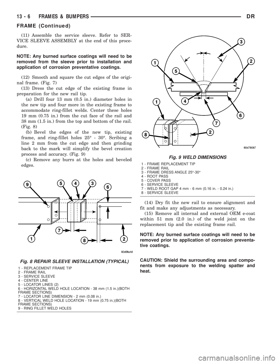
(a) Drill four 13 mm (0.5 in.) diameter holes in
the new tip and four more in the existing frame to
accommodate ring-fillet welds. Center these holes
19 mm (0.75 in.) from the cut face of the rail and
38 mm (1.5 in.) from the top and bottom of the rail.
(Fig. 8)
(b) Bevel the edges of the new tip, existing
frame, and ring-fillet holes 25É - 30É. Scribing a
line 2 mm from the cut edge and then grinding
back to the mark will simplify the bevel creation
process and accuracy. (Fig. 9)
(c) Remove any burrs at the holes and beveled
edges.
(14) Dry fit the new rail to ensure alignment and
fit and make any adjustments as necessary.
(15) Remove all internal and external OEM e-coat
within 51 mm (2.0 in.) of the weld joint on the
replacement tip and the existing frame rail.
NOTE: Any burned surface coatings will need to be
removed prior to application of corrosion preventa-
tive coatings.
CAUTION: Shield the surrounding area and compo-
nents from exposure to the welding spatter and
heat.
Fig. 8 REPAIR SLEEVE INSTALLATION (TYPICAL)
1 - REPLACEMENT FRAME TIP
2 - FRAME RAIL
3 - SERVICE SLEEVE
4 - CENTER LINE
5 - LOCATOR LINES (2)
6 - HORIZONTAL WELD HOLE LOCATION - 38 mm (1.5 in.)(BOTH
FRAME SECTIONS)
7 - LOCATOR LINE DIMENSION-2mm(0.08 in.)
8 - VERTICAL WELD HOLE LOCATION - 19 mm (0.75 in.)(BOTH
FRAME SECTIONS)
9 - RING FILLET WELD HOLES
Fig. 9 WELD DIMENSIONS
1 - FRAME REPLACEMENT TIP
2 - FRAME RAIL
3 - FRAME DRESS ANGLE 25É-30É
4 - ROOT PASS
5 - COVER PASS
6 - SERVICE SLEEVE
7 - WELD ROOT GAP 4 mm-6mm(0.16 in. - 0.24 in.)
8 - SERVICE SLEEVE
13 - 6 FRAMES & BUMPERSDR
FRAME (Continued)
Page 1678 of 2895
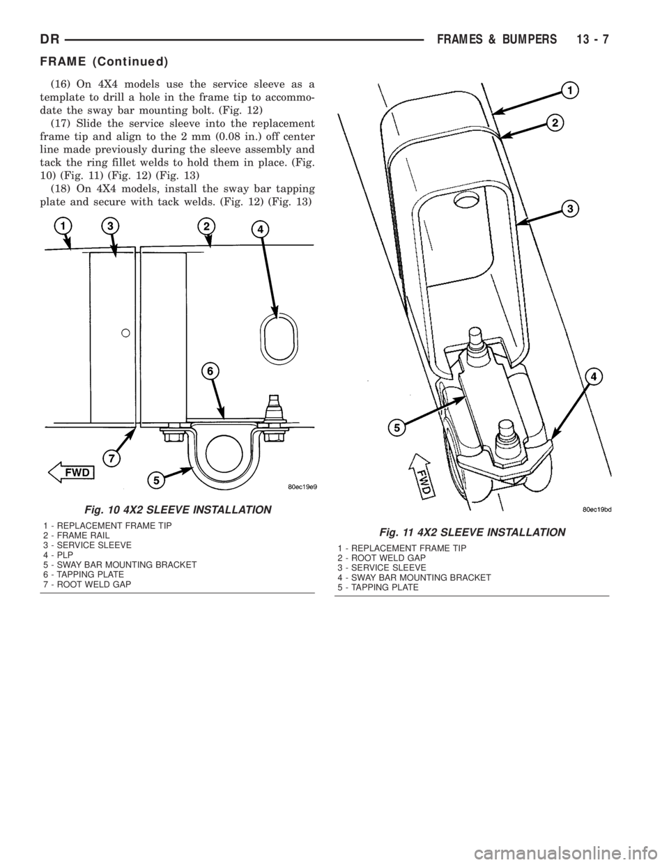
(16) On 4X4 models use the service sleeve as a
template to drill a hole in the frame tip to accommo-
date the sway bar mounting bolt. (Fig. 12)
(17) Slide the service sleeve into the replacement
frame tip and align to the 2 mm (0.08 in.) off center
line made previously during the sleeve assembly and
tack the ring fillet welds to hold them in place. (Fig.
10) (Fig. 11) (Fig. 12) (Fig. 13)
(18) On 4X4 models, install the sway bar tapping
plate and secure with tack welds. (Fig. 12) (Fig. 13)
Fig. 10 4X2 SLEEVE INSTALLATION
1 - REPLACEMENT FRAME TIP
2 - FRAME RAIL
3 - SERVICE SLEEVE
4 - PLP
5 - SWAY BAR MOUNTING BRACKET
6 - TAPPING PLATE
7 - ROOT WELD GAPFig. 11 4X2 SLEEVE INSTALLATION
1 - REPLACEMENT FRAME TIP
2 - ROOT WELD GAP
3 - SERVICE SLEEVE
4 - SWAY BAR MOUNTING BRACKET
5 - TAPPING PLATE
DRFRAMES & BUMPERS 13 - 7
FRAME (Continued)
Page 1679 of 2895
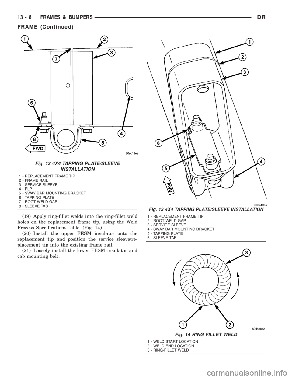
(19) Apply ring-fillet welds into the ring-fillet weld
holes on the replacement frame tip, using the Weld
Process Specifications table. (Fig. 14)
(20) Install the upper FESM insulator onto the
replacement tip and position the service sleeve/re-
placement tip into the existing frame rail.
(21) Loosely install the lower FESM insulator and
cab mounting bolt.
Fig. 12 4X4 TAPPING PLATE/SLEEVE
INSTALLATION
1 - REPLACEMENT FRAME TIP
2 - FRAME RAIL
3 - SERVICE SLEEVE
4 - PLP
5 - SWAY BAR MOUNTING BRACKET
6 - TAPPING PLATE
7 - ROOT WELD GAP
8 - SLEEVE TAB
Fig. 13 4X4 TAPPING PLATE/SLEEVE INSTALLATION
1 - REPLACEMENT FRAME TIP
2 - ROOT WELD GAP
3 - SERVICE SLEEVE
4 - SWAY BAR MOUNTING BRACKET
5 - TAPPING PLATE
6 - SLEEVE TAB
Fig. 14 RING FILLET WELD
1 - WELD START LOCATION
2 - WELD END LOCATION
3 - RING-FILLET WELD
13 - 8 FRAMES & BUMPERSDR
FRAME (Continued)
Page 1680 of 2895
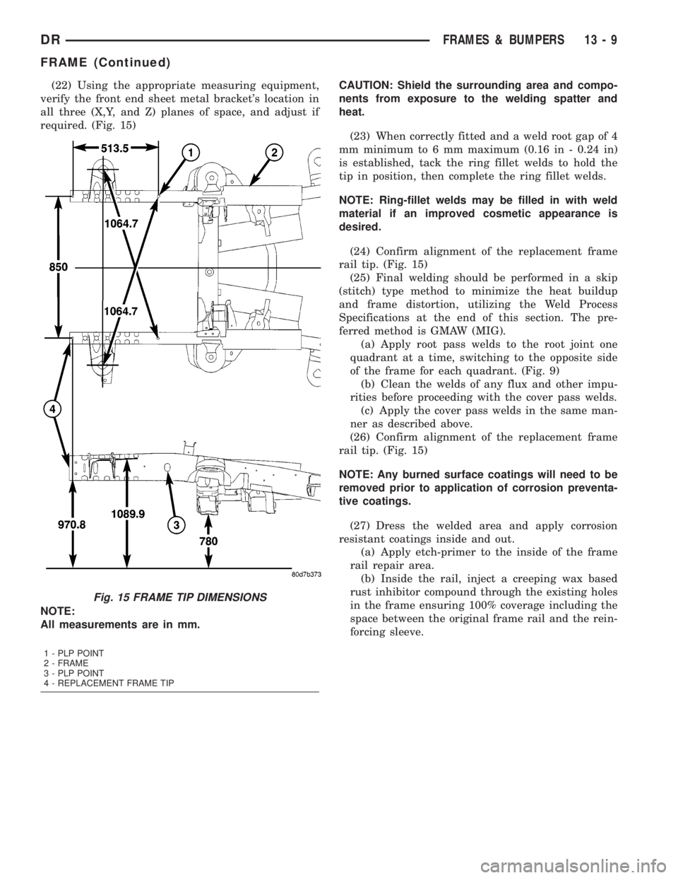
(22) Using the appropriate measuring equipment,
verify the front end sheet metal bracket's location in
all three (X,Y, and Z) planes of space, and adjust if
required. (Fig. 15)CAUTION: Shield the surrounding area and compo-
nents from exposure to the welding spatter and
heat.
(23) When correctly fitted and a weld root gap of 4
mm minimum to 6 mm maximum (0.16 in - 0.24 in)
is established, tack the ring fillet welds to hold the
tip in position, then complete the ring fillet welds.
NOTE: Ring-fillet welds may be filled in with weld
material if an improved cosmetic appearance is
desired.
(24) Confirm alignment of the replacement frame
rail tip. (Fig. 15)
(25) Final welding should be performed in a skip
(stitch) type method to minimize the heat buildup
and frame distortion, utilizing the Weld Process
Specifications at the end of this section. The pre-
ferred method is GMAW (MIG).
(a) Apply root pass welds to the root joint one
quadrant at a time, switching to the opposite side
of the frame for each quadrant. (Fig. 9)
(b) Clean the welds of any flux and other impu-
rities before proceeding with the cover pass welds.
(c) Apply the cover pass welds in the same man-
ner as described above.
(26) Confirm alignment of the replacement frame
rail tip. (Fig. 15)
NOTE: Any burned surface coatings will need to be
removed prior to application of corrosion preventa-
tive coatings.
(27) Dress the welded area and apply corrosion
resistant coatings inside and out.
(a) Apply etch-primer to the inside of the frame
rail repair area.
(b) Inside the rail, inject a creeping wax based
rust inhibitor compound through the existing holes
in the frame ensuring 100% coverage including the
space between the original frame rail and the rein-
forcing sleeve.
Fig. 15 FRAME TIP DIMENSIONS
NOTE:
All measurements are in mm.
1 - PLP POINT
2 - FRAME
3 - PLP POINT
4 - REPLACEMENT FRAME TIP
DRFRAMES & BUMPERS 13 - 9
FRAME (Continued)