DODGE RAM 2003 Service Repair Manual
Manufacturer: DODGE, Model Year: 2003, Model line: RAM, Model: DODGE RAM 2003Pages: 2895, PDF Size: 83.15 MB
Page 2651 of 2895
SEATS
TABLE OF CONTENTS
page page
CENTER SEAT
REMOVAL.............................76
INSTALLATION.........................77
CENTER ARMREST / SEAT BACK
REMOVAL.............................77
INSTALLATION.........................78
CENTER SEAT BACK INERTIA HINGE COVER
REMOVAL.............................78
INSTALLATION.........................78
CENTER SEAT BACK HINGE
REMOVAL.............................79
INSTALLATION.........................80
CENTER SEAT BACK LID
REMOVAL.............................80
INSTALLATION.........................80
CENTER SEAT CUSHION
REMOVAL.............................80
INSTALLATION.........................80
CENTER SEAT CUSHION COVER
REMOVAL.............................81
INSTALLATION.........................81
UNDER SEAT STORAGE BIN
REMOVAL.............................81
INSTALLATION.........................81
UNDER SEAT STORAGE BIN COVERING
REMOVAL.............................81
INSTALLATION.........................81
UNDER SEAT STORAGE BIN LATCH
REMOVAL.............................81
INSTALLATION.........................81
HEADREST
REMOVAL.............................82
INSTALLATION.........................82
HEADREST SLEEVE
REMOVAL.............................82INSTALLATION.........................82
SEAT - FRONT
REMOVAL.............................82
INSTALLATION.........................82
SEAT BACK CUSHION / COVER - FRONT
REMOVAL.............................83
INSTALLATION.........................83
SEAT CUSHION / COVER - FRONT
REMOVAL.............................83
INSTALLATION.........................83
SEAT TRACK
REMOVAL.............................83
INSTALLATION.........................83
SEAT - REAR
REMOVAL.............................84
INSTALLATION.........................84
SEAT BACK - REAR
REMOVAL.............................84
INSTALLATION.........................84
SEAT BACK CUSHION / COVER - REAR
REMOVAL.............................85
INSTALLATION.........................85
SEAT CUSHION / COVER - REAR
REMOVAL.............................85
INSTALLATION.........................85
SEAT CUSHION FRAME - REAR
REMOVAL.............................85
INSTALLATION.........................85
SEAT BACK REAR - FOOTMANS LOOP
BRACKETS
REMOVAL.............................85
INSTALLATION.........................85
CENTER SEAT
REMOVAL
NOTE: Do not reuse the seat fasteners, always
replace with new ones.
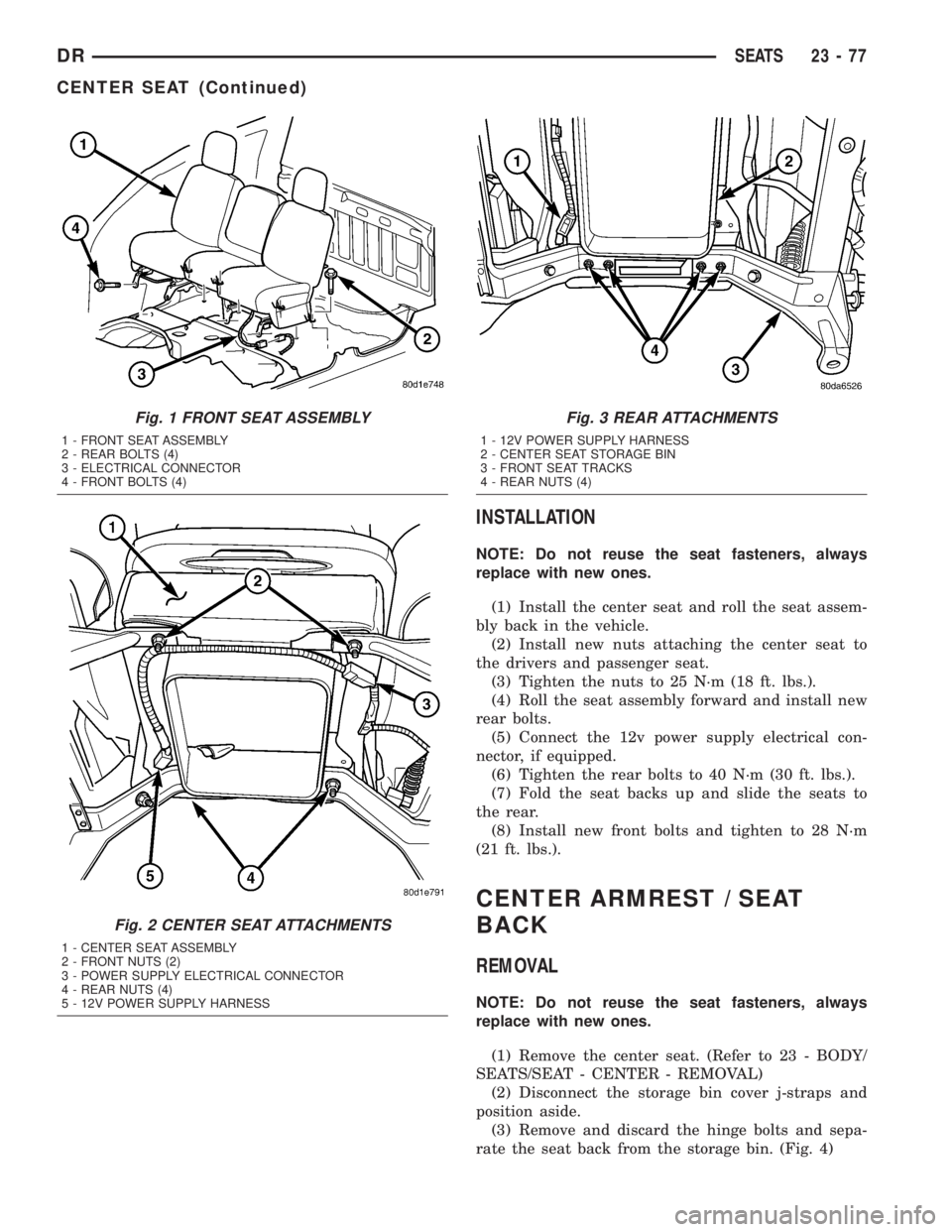
(1) Remove and discard the front bolts. (Fig. 1)
(2) Position the seats forward, remove the rear
bolts and discard.
(3) Disconnect the 12v power supply electrical con-
nector, if equipped. (Fig. 2)(4) Fold the seat backs forward and roll the seat
assembly back in the vehicle.
(5) Remove the nuts attaching the center seat to
the drivers seat and the passenger seat and discard.
(Fig. 3)
(6) Roll the seat assembly forward and remove the
center seat portion.
23 - 76 SEATSDR
Page 2652 of 2895
INSTALLATION
NOTE: Do not reuse the seat fasteners, always
replace with new ones.
(1) Install the center seat and roll the seat assem-
bly back in the vehicle.
(2) Install new nuts attaching the center seat to
the drivers and passenger seat.
(3) Tighten the nuts to 25 N´m (18 ft. lbs.).
(4) Roll the seat assembly forward and install new
rear bolts.
(5) Connect the 12v power supply electrical con-
nector, if equipped.
(6) Tighten the rear bolts to 40 N´m (30 ft. lbs.).
(7) Fold the seat backs up and slide the seats to
the rear.
(8) Install new front bolts and tighten to 28 N´m
(21 ft. lbs.).
CENTER ARMREST / SEAT
BACK
REMOVAL
NOTE: Do not reuse the seat fasteners, always
replace with new ones.
(1) Remove the center seat. (Refer to 23 - BODY/
SEATS/SEAT - CENTER - REMOVAL)
(2) Disconnect the storage bin cover j-straps and
position aside.
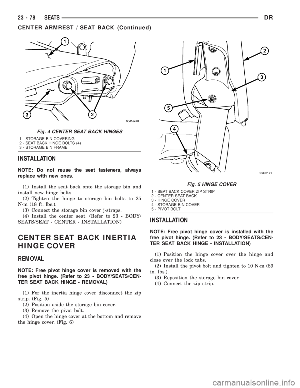
(3) Remove and discard the hinge bolts and sepa-
rate the seat back from the storage bin. (Fig. 4)
Fig. 1 FRONT SEAT ASSEMBLY
1 - FRONT SEAT ASSEMBLY
2 - REAR BOLTS (4)
3 - ELECTRICAL CONNECTOR
4 - FRONT BOLTS (4)
Fig. 2 CENTER SEAT ATTACHMENTS
1 - CENTER SEAT ASSEMBLY
2 - FRONT NUTS (2)
3 - POWER SUPPLY ELECTRICAL CONNECTOR
4 - REAR NUTS (4)
5 - 12V POWER SUPPLY HARNESS
Fig. 3 REAR ATTACHMENTS
1 - 12V POWER SUPPLY HARNESS
2 - CENTER SEAT STORAGE BIN
3 - FRONT SEAT TRACKS
4 - REAR NUTS (4)
DRSEATS 23 - 77
CENTER SEAT (Continued)
Page 2653 of 2895
INSTALLATION
NOTE: Do not reuse the seat fasteners, always
replace with new ones.
(1) Install the seat back onto the storage bin and
install new hinge bolts.
(2) Tighten the hinge to storage bin bolts to 25
N´m (18 ft. lbs.).
(3) Connect the storage bin cover j-straps.
(4) Install the center seat. (Refer to 23 - BODY/
SEATS/SEAT - CENTER - INSTALLATION)
CENTER SEAT BACK INERTIA
HINGE COVER
REMOVAL
NOTE: Free pivot hinge cover is removed with the
free pivot hinge. (Refer to 23 - BODY/SEATS/CEN-
TER SEAT BACK HINGE - REMOVAL)
(1) For the inertia hinge cover disconnect the zip
strip. (Fig. 5)
(2) Position aside the storage bin cover.
(3) Remove the pivot bolt.
(4) Open the hinge cover at the bottom and remove
the hinge cover. (Fig. 6)
INSTALLATION
NOTE: Free pivot hinge cover is installed with the
free pivot hinge. (Refer to 23 - BODY/SEATS/CEN-
TER SEAT BACK HINGE - INSTALLATION)
(1) Position the hinge cover over the hinge and
close over the lock tabs.
(2) Install the pivot bolt and tighten to 10 N´m (89
in. lbs.).
(3) Reposition the storage bin cover.
(4) Connect the zip strip.
Fig. 4 CENTER SEAT BACK HINGES
1 - STORAGE BIN COVERING
2 - SEAT BACK HINGE BOLTS (4)
3 - STORAGE BIN FRAME
Fig. 5 HINGE COVER
1 - SEAT BACK COVER ZIP STRIP
2 - CENTER SEAT BACK
3 - HINGE COVER
4 - STORAGE BIN COVER
5 - PIVOT BOLT
23 - 78 SEATSDR
CENTER ARMREST / SEAT BACK (Continued)
Page 2654 of 2895
CENTER SEAT BACK HINGE
REMOVAL
NOTE: Do not reuse the seat fasteners, always
replace with new ones.
(1) Remove the seat back. (Refer to 23 - BODY/
SEATS/CENTER ARMREST / SEAT BACK -
REMOVAL)
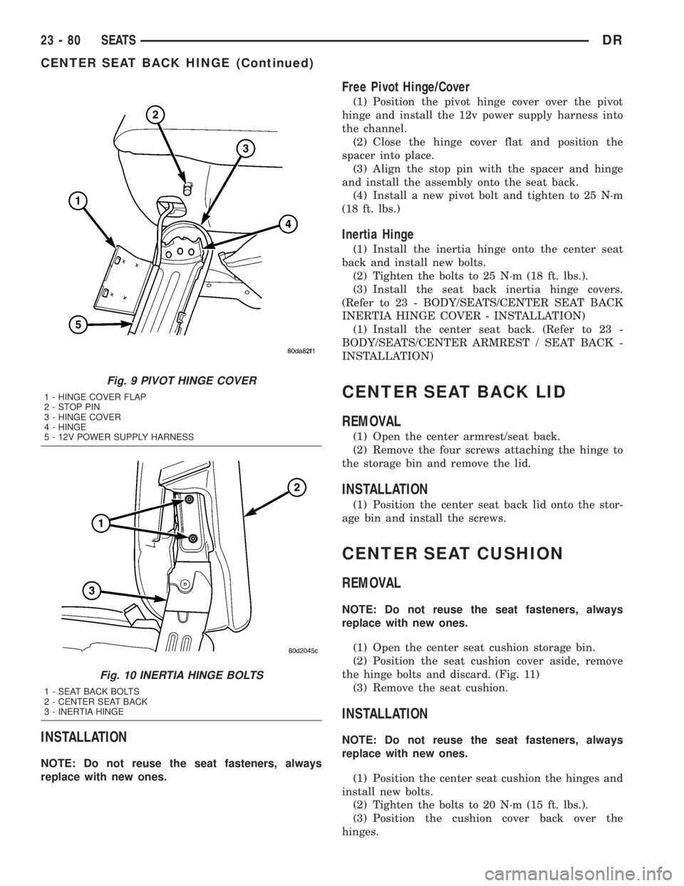
Free Pivot Hinge/Cover
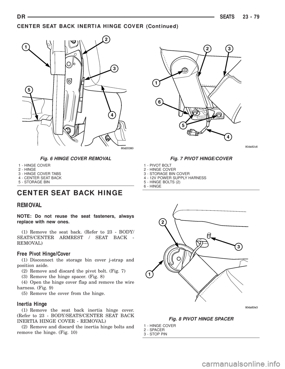
(1) Disconnect the storage bin cover j-strap and
position aside.
(2) Remove and discard the pivot bolt. (Fig. 7)
(3) Remove the hinge spacer. (Fig. 8)
(4) Open the hinge cover flap and remove the wire
harness. (Fig. 9)
(5) Remove the cover from the hinge.
Inertia Hinge
(1) Remove the seat back inertia hinge cover.
(Refer to 23 - BODY/SEATS/CENTER SEAT BACK
INERTIA HINGE COVER - REMOVAL)
(2) Remove and discard the inertia hinge bolts and
remove the hinge. (Fig. 10)
Fig. 6 HINGE COVER REMOVAL
1 - HINGE COVER
2 - HINGE
3 - HINGE COVER TABS
4 - CENTER SEAT BACK
5 - STORAGE BIN
Fig. 7 PIVOT HINGE/COVER
1 - PIVOT BOLT
2 - HINGE COVER
3 - STORAGE BIN COVER
4 - 12V POWER SUPPLY HARNESS
5 - HINGE BOLTS (2)
6 - HINGE
Fig. 8 PIVOT HINGE SPACER
1 - HINGE COVER
2 - SPACER
3-STOPPIN
DRSEATS 23 - 79
CENTER SEAT BACK INERTIA HINGE COVER (Continued)
Page 2655 of 2895
INSTALLATION
NOTE: Do not reuse the seat fasteners, always
replace with new ones.
Free Pivot Hinge/Cover
(1) Position the pivot hinge cover over the pivot
hinge and install the 12v power supply harness into
the channel.
(2) Close the hinge cover flat and position the
spacer into place.
(3) Align the stop pin with the spacer and hinge
and install the assembly onto the seat back.
(4) Install a new pivot bolt and tighten to 25 N´m
(18 ft. lbs.)
Inertia Hinge
(1) Install the inertia hinge onto the center seat
back and install new bolts.
(2) Tighten the bolts to 25 N´m (18 ft. lbs.).
(3) Install the seat back inertia hinge covers.
(Refer to 23 - BODY/SEATS/CENTER SEAT BACK
INERTIA HINGE COVER - INSTALLATION)
(1) Install the center seat back. (Refer to 23 -
BODY/SEATS/CENTER ARMREST / SEAT BACK -
INSTALLATION)
CENTER SEAT BACK LID
REMOVAL
(1) Open the center armrest/seat back.
(2) Remove the four screws attaching the hinge to
the storage bin and remove the lid.
INSTALLATION
(1) Position the center seat back lid onto the stor-
age bin and install the screws.
CENTER SEAT CUSHION
REMOVAL
NOTE: Do not reuse the seat fasteners, always
replace with new ones.
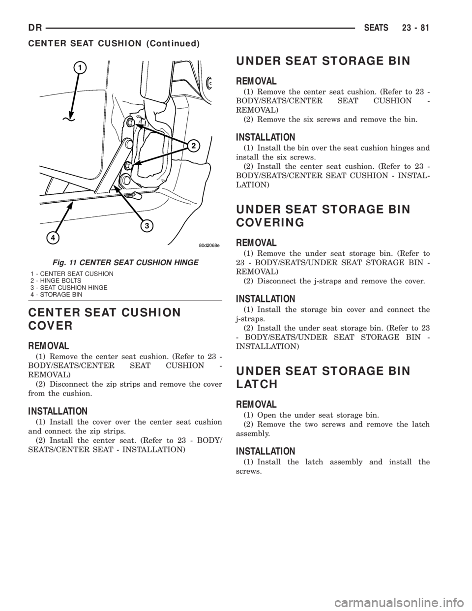
(1) Open the center seat cushion storage bin.
(2) Position the seat cushion cover aside, remove
the hinge bolts and discard. (Fig. 11)
(3) Remove the seat cushion.
INSTALLATION
NOTE: Do not reuse the seat fasteners, always
replace with new ones.
(1) Position the center seat cushion the hinges and
install new bolts.
(2) Tighten the bolts to 20 N´m (15 ft. lbs.).
(3) Position the cushion cover back over the
hinges.
Fig. 9 PIVOT HINGE COVER
1 - HINGE COVER FLAP
2-STOPPIN
3 - HINGE COVER
4 - HINGE
5 - 12V POWER SUPPLY HARNESS
Fig. 10 INERTIA HINGE BOLTS
1 - SEAT BACK BOLTS
2 - CENTER SEAT BACK
3 - INERTIA HINGE
23 - 80 SEATSDR
CENTER SEAT BACK HINGE (Continued)
Page 2656 of 2895
CENTER SEAT CUSHION
COVER
REMOVAL
(1) Remove the center seat cushion. (Refer to 23 -
BODY/SEATS/CENTER SEAT CUSHION -
REMOVAL)
(2) Disconnect the zip strips and remove the cover
from the cushion.
INSTALLATION
(1) Install the cover over the center seat cushion
and connect the zip strips.
(2) Install the center seat. (Refer to 23 - BODY/
SEATS/CENTER SEAT - INSTALLATION)
UNDER SEAT STORAGE BIN
REMOVAL
(1) Remove the center seat cushion. (Refer to 23 -
BODY/SEATS/CENTER SEAT CUSHION -
REMOVAL)
(2) Remove the six screws and remove the bin.
INSTALLATION
(1) Install the bin over the seat cushion hinges and
install the six screws.
(2) Install the center seat cushion. (Refer to 23 -
BODY/SEATS/CENTER SEAT CUSHION - INSTAL-
LATION)
UNDER SEAT STORAGE BIN
COVERING
REMOVAL
(1) Remove the under seat storage bin. (Refer to
23 - BODY/SEATS/UNDER SEAT STORAGE BIN -
REMOVAL)
(2) Disconnect the j-straps and remove the cover.
INSTALLATION
(1) Install the storage bin cover and connect the
j-straps.
(2) Install the under seat storage bin. (Refer to 23
- BODY/SEATS/UNDER SEAT STORAGE BIN -
INSTALLATION)
UNDER SEAT STORAGE BIN
LATCH
REMOVAL
(1) Open the under seat storage bin.
(2) Remove the two screws and remove the latch
assembly.
INSTALLATION
(1) Install the latch assembly and install the
screws.
Fig. 11 CENTER SEAT CUSHION HINGE
1 - CENTER SEAT CUSHION
2 - HINGE BOLTS
3 - SEAT CUSHION HINGE
4 - STORAGE BIN
DRSEATS 23 - 81
CENTER SEAT CUSHION (Continued)
Page 2657 of 2895
HEADREST
REMOVAL
(1) Raise the headrest.
(2) Press the headrest release button and remove
the headrest.
INSTALLATION
(1) Position the headrest.
(2) Press the release button and install the head-
rest.
HEADREST SLEEVE
REMOVAL
(1) Remove the headrest. (Refer to 23 - BODY/
SEATS/HEADREST - REMOVAL)
(2) Grasp the sleeves and pull up and out of the
seat back to remove.
INSTALLATION
(1) Position each headrest sleeve into correct seat
back hole and press into place fully.
(2) Install the headrest. (Refer to 23 - BODY/
SEATS/HEADREST - INSTALLATION)
SEAT - FRONT
REMOVAL
NOTE: Do not reuse the seat fasteners, always
replace with new ones.
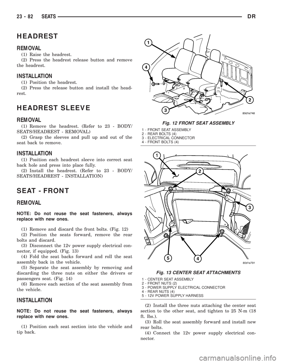
(1) Remove and discard the front bolts. (Fig. 12)
(2) Position the seats forward, remove the rear
bolts and discard.
(3) Disconnect the 12v power supply electrical con-
nector, if equipped. (Fig. 13)
(4) Fold the seat backs forward and roll the seat
assembly back in the vehicle.
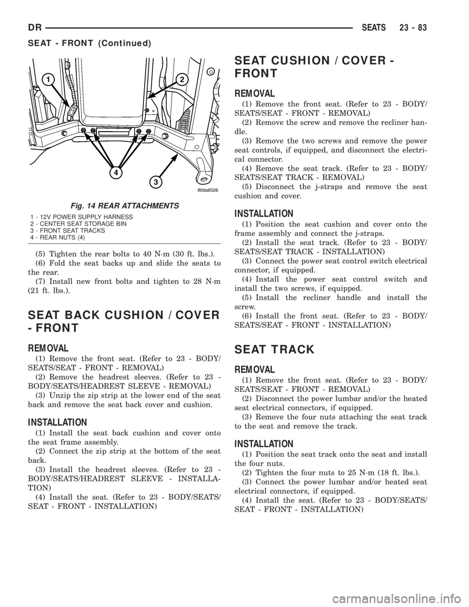
(5) Separate the seat assembly by removing and
discarding the three nuts on either the drivers or
passengers seat. (Fig. 14)
(6) Remove each section of the seat assembly from
the vehicle.
INSTALLATION
NOTE: Do not reuse the seat fasteners, always
replace with new ones.
(1) Position each seat section into the vehicle and
tip back.(2) Install the three nuts attaching the center seat
section to the other seat, and tighten to 25 N´m (18
ft. lbs.).
(3) Roll the seat assembly forward and install new
rear bolts.
(4) Connect the 12v power supply electrical con-
nector.
Fig. 12 FRONT SEAT ASSEMBLY
1 - FRONT SEAT ASSEMBLY
2 - REAR BOLTS (4)
3 - ELECTRICAL CONNECTOR
4 - FRONT BOLTS (4)
Fig. 13 CENTER SEAT ATTACHMENTS
1 - CENTER SEAT ASSEMBLY
2 - FRONT NUTS (2)
3 - POWER SUPPLY ELECTRICAL CONNECTOR
4 - REAR NUTS (4)
5 - 12V POWER SUPPLY HARNESS
23 - 82 SEATSDR
Page 2658 of 2895
(5) Tighten the rear bolts to 40 N´m (30 ft. lbs.).
(6) Fold the seat backs up and slide the seats to
the rear.
(7) Install new front bolts and tighten to 28 N´m
(21 ft. lbs.).
SEAT BACK CUSHION / COVER
- FRONT
REMOVAL
(1) Remove the front seat. (Refer to 23 - BODY/
SEATS/SEAT - FRONT - REMOVAL)
(2) Remove the headrest sleeves. (Refer to 23 -
BODY/SEATS/HEADREST SLEEVE - REMOVAL)
(3) Unzip the zip strip at the lower end of the seat
back and remove the seat back cover and cushion.
INSTALLATION
(1) Install the seat back cushion and cover onto
the seat frame assembly.
(2) Connect the zip strip at the bottom of the seat
back.
(3) Install the headrest sleeves. (Refer to 23 -
BODY/SEATS/HEADREST SLEEVE - INSTALLA-
TION)
(4) Install the seat. (Refer to 23 - BODY/SEATS/
SEAT - FRONT - INSTALLATION)
SEAT CUSHION / COVER -
FRONT
REMOVAL
(1) Remove the front seat. (Refer to 23 - BODY/
SEATS/SEAT - FRONT - REMOVAL)
(2) Remove the screw and remove the recliner han-
dle.
(3) Remove the two screws and remove the power
seat controls, if equipped, and disconnect the electri-
cal connector.
(4) Remove the seat track. (Refer to 23 - BODY/
SEATS/SEAT TRACK - REMOVAL)
(5) Disconnect the j-straps and remove the seat
cushion and cover.
INSTALLATION
(1) Position the seat cushion and cover onto the
frame assembly and connect the j-straps.
(2) Install the seat track. (Refer to 23 - BODY/
SEATS/SEAT TRACK - INSTALLATION)
(3) Connect the power seat control switch electrical
connector, if equipped.
(4) Install the power seat control switch and
install the two screws, if equipped.
(5) Install the recliner handle and install the
screw.
(6) Install the front seat. (Refer to 23 - BODY/
SEATS/SEAT - FRONT - INSTALLATION)
SEAT TRACK
REMOVAL
(1) Remove the front seat. (Refer to 23 - BODY/
SEATS/SEAT - FRONT - REMOVAL)
(2) Disconnect the power lumbar and/or the heated
seat electrical connectors, if equipped.
(3) Remove the four nuts attaching the seat track
to the seat and remove the track.
INSTALLATION
(1) Position the seat track onto the seat and install
the four nuts.
(2) Tighten the four nuts to 25 N´m (18 ft. lbs.).
(3) Connect the power lumbar and/or heated seat
electrical connectors, if equipped.
(4) Install the seat. (Refer to 23 - BODY/SEATS/
SEAT - FRONT - INSTALLATION)
Fig. 14 REAR ATTACHMENTS
1 - 12V POWER SUPPLY HARNESS
2 - CENTER SEAT STORAGE BIN
3 - FRONT SEAT TRACKS
4 - REAR NUTS (4)
DRSEATS 23 - 83
SEAT - FRONT (Continued)
Page 2659 of 2895
SEAT - REAR
REMOVAL
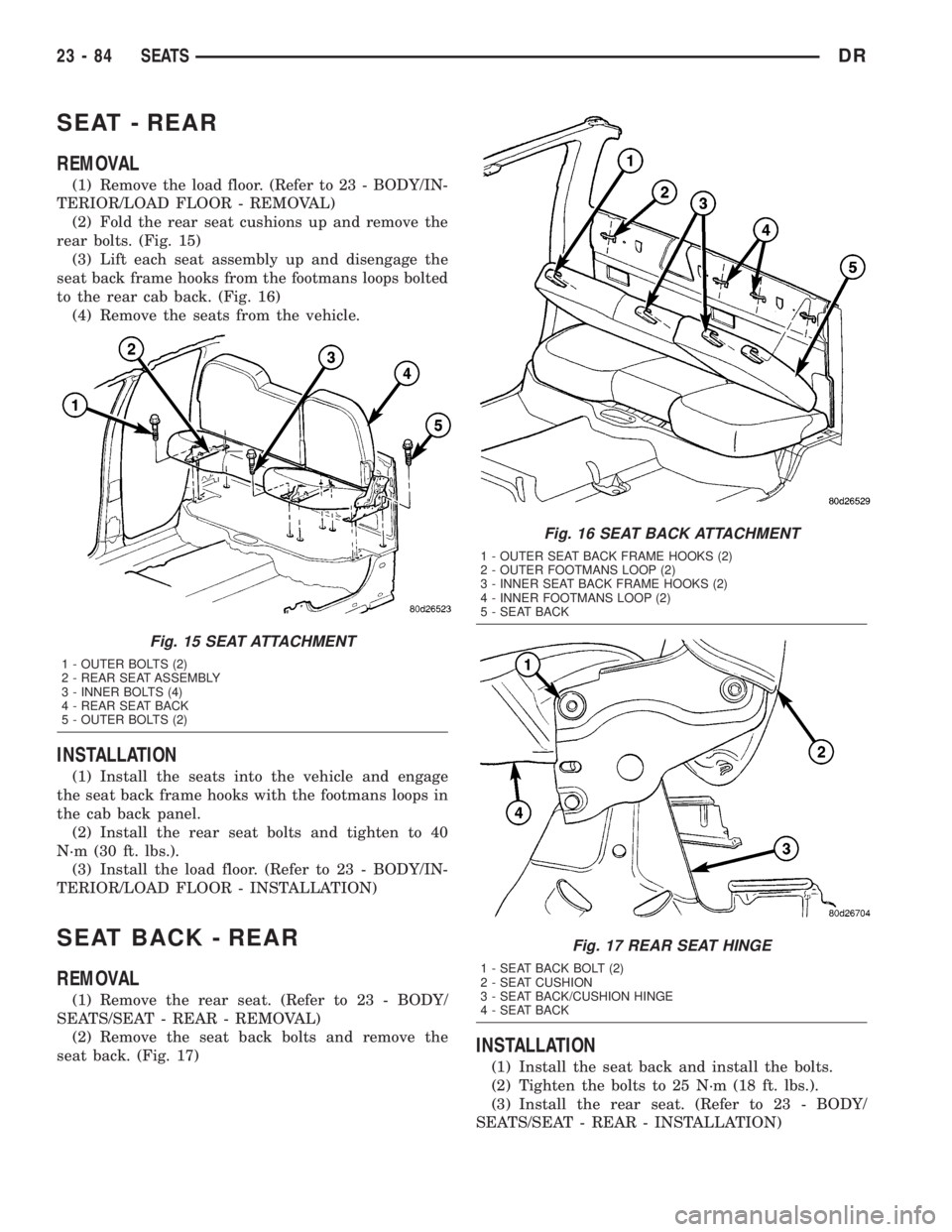
(1) Remove the load floor. (Refer to 23 - BODY/IN-
TERIOR/LOAD FLOOR - REMOVAL)
(2) Fold the rear seat cushions up and remove the
rear bolts. (Fig. 15)
(3) Lift each seat assembly up and disengage the
seat back frame hooks from the footmans loops bolted
to the rear cab back. (Fig. 16)
(4) Remove the seats from the vehicle.
INSTALLATION
(1) Install the seats into the vehicle and engage
the seat back frame hooks with the footmans loops in
the cab back panel.
(2) Install the rear seat bolts and tighten to 40
N´m (30 ft. lbs.).
(3) Install the load floor. (Refer to 23 - BODY/IN-
TERIOR/LOAD FLOOR - INSTALLATION)
SEAT BACK - REAR
REMOVAL
(1) Remove the rear seat. (Refer to 23 - BODY/
SEATS/SEAT - REAR - REMOVAL)
(2) Remove the seat back bolts and remove the
seat back. (Fig. 17)
INSTALLATION
(1) Install the seat back and install the bolts.
(2) Tighten the bolts to 25 N´m (18 ft. lbs.).
(3) Install the rear seat. (Refer to 23 - BODY/
SEATS/SEAT - REAR - INSTALLATION)
Fig. 15 SEAT ATTACHMENT
1 - OUTER BOLTS (2)
2 - REAR SEAT ASSEMBLY
3 - INNER BOLTS (4)
4 - REAR SEAT BACK
5 - OUTER BOLTS (2)
Fig. 16 SEAT BACK ATTACHMENT
1 - OUTER SEAT BACK FRAME HOOKS (2)
2 - OUTER FOOTMANS LOOP (2)
3 - INNER SEAT BACK FRAME HOOKS (2)
4 - INNER FOOTMANS LOOP (2)
5 - SEAT BACK
Fig. 17 REAR SEAT HINGE
1 - SEAT BACK BOLT (2)
2 - SEAT CUSHION
3 - SEAT BACK/CUSHION HINGE
4 - SEAT BACK
23 - 84 SEATSDR
Page 2660 of 2895
SEAT BACK CUSHION / COVER
- REAR
REMOVAL
(1) Remove the rear seat back. (Refer to 23 -
BODY/SEATS/SEAT BACK - REAR - REMOVAL)
(2) Unzip the zip strip at the bottom of the seat
back and remove the cover and cushion.
INSTALLATION
(1) Install the seat back cushion and cover and
connect the zip strip.
(2) Install the seat back. (Refer to 23 - BODY/
SEATS/SEAT BACK - REAR - INSTALLATION)
SEAT CUSHION / COVER -
REAR
REMOVAL
(1) Remove the rear seat. (Refer to 23 - BODY/
SEATS/SEAT - REAR - REMOVAL)
(2) Remove the screws and remove the grocery bag
hooks, if equipped.
(3) Separate the zip strip at the rear of the seat
cushion and remove the cushion and cover.
INSTALLATION
(1) Install the seat cushion and cover over the
cushion frame assembly and connect the zip strip.
(2) Install the grocery bag hooks and screws, if
equipped.
(3) Install the seat. (Refer to 23 - BODY/SEATS/
SEAT - REAR - INSTALLATION)
SEAT CUSHION FRAME - REAR
REMOVAL
(1) Remove the seat cushion/cover. (Refer to 23 -
BODY/SEATS/SEAT CUSHION / COVER - REAR -
REMOVAL)
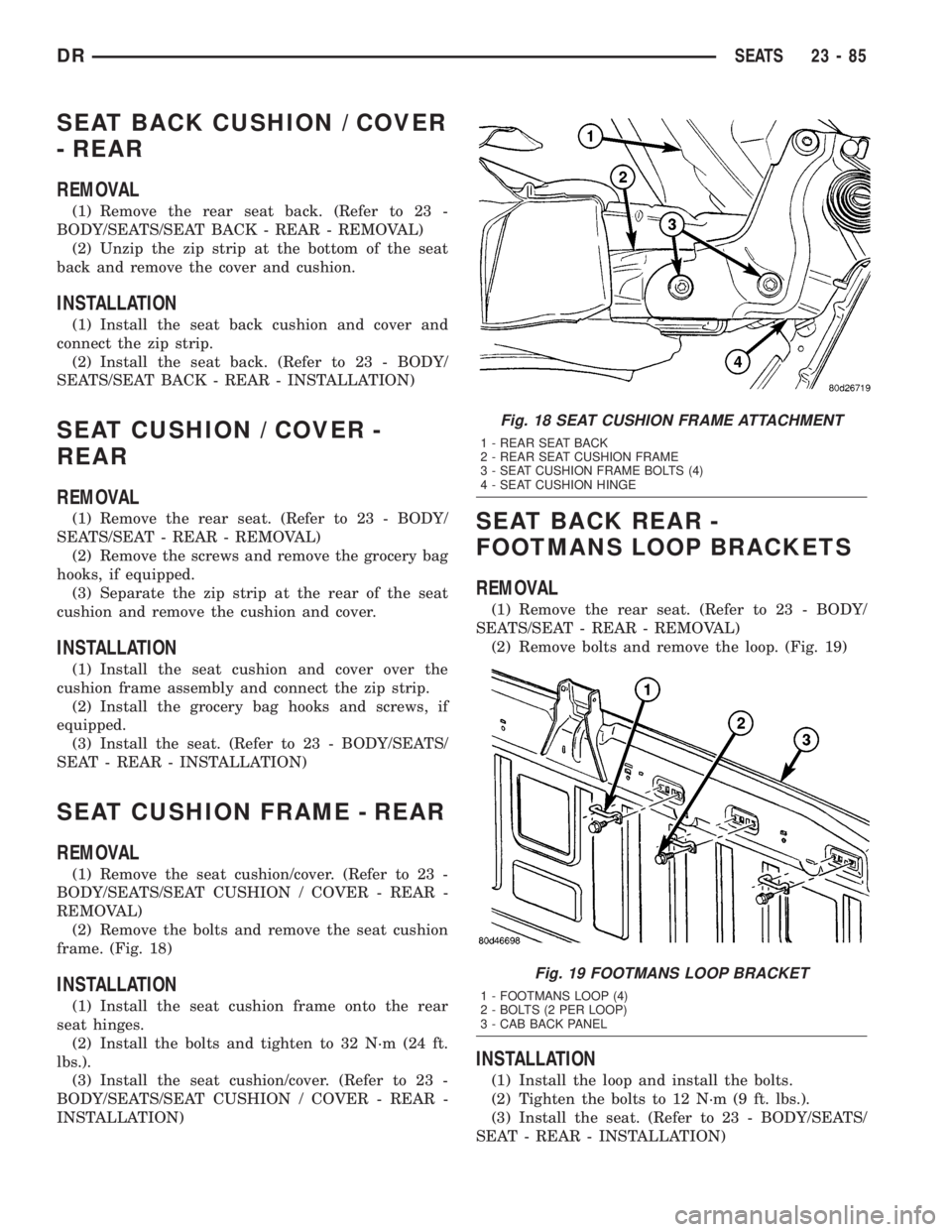
(2) Remove the bolts and remove the seat cushion
frame. (Fig. 18)
INSTALLATION
(1) Install the seat cushion frame onto the rear
seat hinges.
(2) Install the bolts and tighten to 32 N´m (24 ft.
lbs.).
(3) Install the seat cushion/cover. (Refer to 23 -
BODY/SEATS/SEAT CUSHION / COVER - REAR -
INSTALLATION)
SEAT BACK REAR -
FOOTMANS LOOP BRACKETS
REMOVAL
(1) Remove the rear seat. (Refer to 23 - BODY/
SEATS/SEAT - REAR - REMOVAL)
(2) Remove bolts and remove the loop. (Fig. 19)
INSTALLATION
(1) Install the loop and install the bolts.
(2) Tighten the bolts to 12 N´m (9 ft. lbs.).
(3) Install the seat. (Refer to 23 - BODY/SEATS/
SEAT - REAR - INSTALLATION)
Fig. 18 SEAT CUSHION FRAME ATTACHMENT
1 - REAR SEAT BACK
2 - REAR SEAT CUSHION FRAME
3 - SEAT CUSHION FRAME BOLTS (4)
4 - SEAT CUSHION HINGE
Fig. 19 FOOTMANS LOOP BRACKET
1 - FOOTMANS LOOP (4)
2 - BOLTS (2 PER LOOP)
3 - CAB BACK PANEL
DRSEATS 23 - 85