bushing DODGE RAM 2003 Service Manual PDF
[x] Cancel search | Manufacturer: DODGE, Model Year: 2003, Model line: RAM, Model: DODGE RAM 2003Pages: 2895, PDF Size: 83.15 MB
Page 1871 of 2895
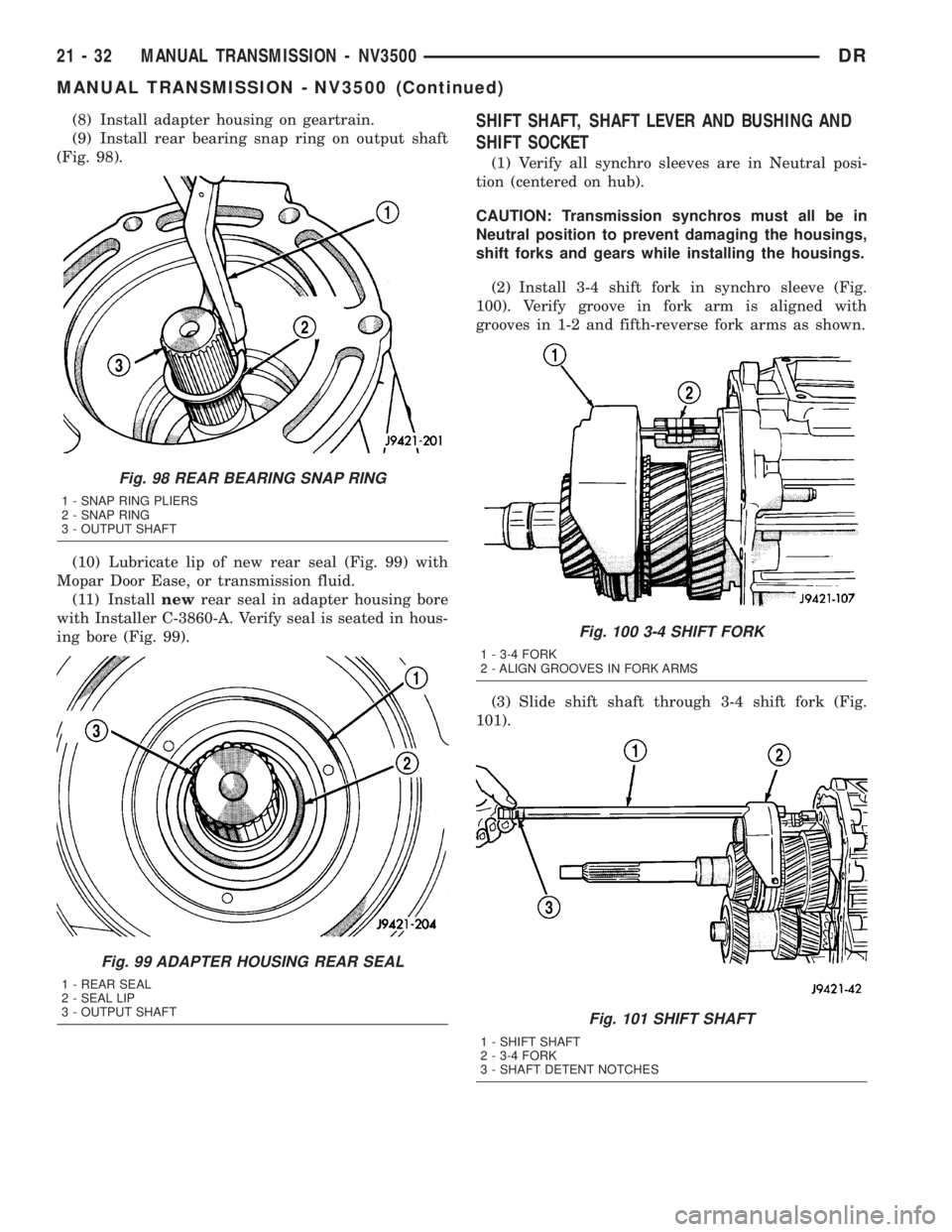
(8) Install adapter housing on geartrain.
(9) Install rear bearing snap ring on output shaft
(Fig. 98).
(10) Lubricate lip of new rear seal (Fig. 99) with
Mopar Door Ease, or transmission fluid.
(11) Installnewrear seal in adapter housing bore
with Installer C-3860-A. Verify seal is seated in hous-
ing bore (Fig. 99).SHIFT SHAFT, SHAFT LEVER AND BUSHING AND
SHIFT SOCKET
(1) Verify all synchro sleeves are in Neutral posi-
tion (centered on hub).
CAUTION: Transmission synchros must all be in
Neutral position to prevent damaging the housings,
shift forks and gears while installing the housings.
(2) Install 3-4 shift fork in synchro sleeve (Fig.
100). Verify groove in fork arm is aligned with
grooves in 1-2 and fifth-reverse fork arms as shown.
(3) Slide shift shaft through 3-4 shift fork (Fig.
101).
Fig. 98 REAR BEARING SNAP RING
1 - SNAP RING PLIERS
2 - SNAP RING
3 - OUTPUT SHAFT
Fig. 99 ADAPTER HOUSING REAR SEAL
1 - REAR SEAL
2 - SEAL LIP
3 - OUTPUT SHAFT
Fig. 100 3-4 SHIFT FORK
1 - 3-4 FORK
2 - ALIGN GROOVES IN FORK ARMS
Fig. 101 SHIFT SHAFT
1 - SHIFT SHAFT
2 - 3-4 FORK
3 - SHAFT DETENT NOTCHES
21 - 32 MANUAL TRANSMISSION - NV3500DR
MANUAL TRANSMISSION - NV3500 (Continued)
Page 1872 of 2895
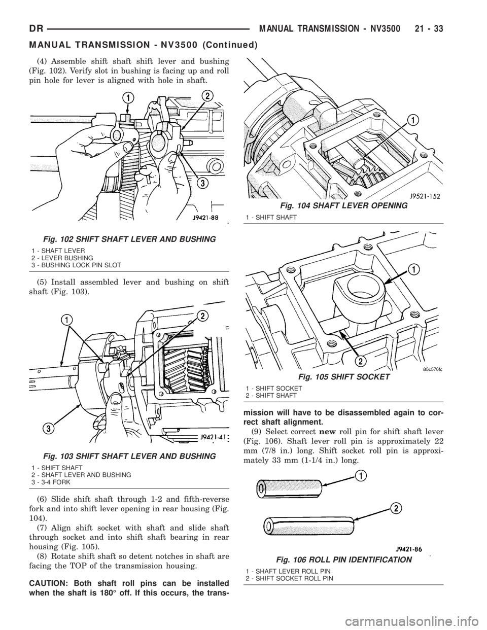
(4) Assemble shift shaft shift lever and bushing
(Fig. 102). Verify slot in bushing is facing up and roll
pin hole for lever is aligned with hole in shaft.
(5) Install assembled lever and bushing on shift
shaft (Fig. 103).
(6) Slide shift shaft through 1-2 and fifth-reverse
fork and into shift lever opening in rear housing (Fig.
104).
(7) Align shift socket with shaft and slide shaft
through socket and into shift shaft bearing in rear
housing (Fig. 105).
(8) Rotate shift shaft so detent notches in shaft are
facing the TOP of the transmission housing.
CAUTION: Both shaft roll pins can be installed
when the shaft is 180É off. If this occurs, the trans-mission will have to be disassembled again to cor-
rect shaft alignment.
(9) Select correctnewroll pin for shift shaft lever
(Fig. 106). Shaft lever roll pin is approximately 22
mm (7/8 in.) long. Shift socket roll pin is approxi-
mately 33 mm (1-1/4 in.) long.
Fig. 102 SHIFT SHAFT LEVER AND BUSHING
1 - SHAFT LEVER
2 - LEVER BUSHING
3 - BUSHING LOCK PIN SLOT
Fig. 103 SHIFT SHAFT LEVER AND BUSHING
1 - SHIFT SHAFT
2 - SHAFT LEVER AND BUSHING
3 - 3-4 FORK
Fig. 104 SHAFT LEVER OPENING
1 - SHIFT SHAFT
Fig. 105 SHIFT SOCKET
1 - SHIFT SOCKET
2 - SHIFT SHAFT
Fig. 106 ROLL PIN IDENTIFICATION
1 - SHAFT LEVER ROLL PIN
2 - SHIFT SOCKET ROLL PIN
DRMANUAL TRANSMISSION - NV3500 21 - 33
MANUAL TRANSMISSION - NV3500 (Continued)
Page 1873 of 2895
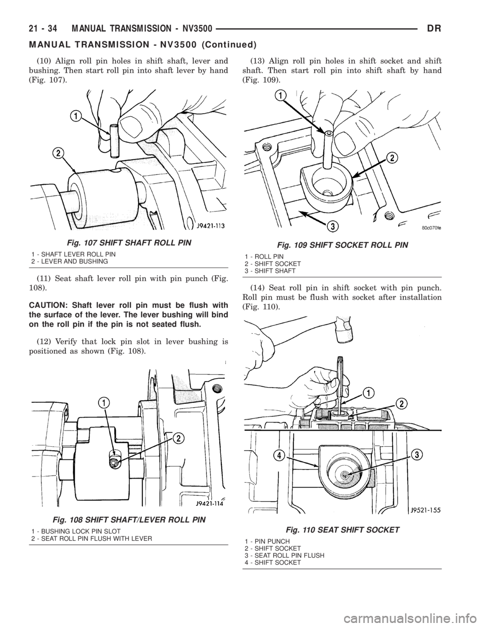
(10) Align roll pin holes in shift shaft, lever and
bushing. Then start roll pin into shaft lever by hand
(Fig. 107).
(11) Seat shaft lever roll pin with pin punch (Fig.
108).
CAUTION: Shaft lever roll pin must be flush with
the surface of the lever. The lever bushing will bind
on the roll pin if the pin is not seated flush.
(12) Verify that lock pin slot in lever bushing is
positioned as shown (Fig. 108).(13) Align roll pin holes in shift socket and shift
shaft. Then start roll pin into shift shaft by hand
(Fig. 109).
(14) Seat roll pin in shift socket with pin punch.
Roll pin must be flush with socket after installation
(Fig. 110).
Fig. 107 SHIFT SHAFT ROLL PIN
1 - SHAFT LEVER ROLL PIN
2 - LEVER AND BUSHING
Fig. 108 SHIFT SHAFT/LEVER ROLL PIN
1 - BUSHING LOCK PIN SLOT
2 - SEAT ROLL PIN FLUSH WITH LEVER
Fig. 109 SHIFT SOCKET ROLL PIN
1 - ROLL PIN
2 - SHIFT SOCKET
3 - SHIFT SHAFT
Fig. 110 SEAT SHIFT SOCKET
1 - PIN PUNCH
2 - SHIFT SOCKET
3 - SEAT ROLL PIN FLUSH
4 - SHIFT SOCKET
21 - 34 MANUAL TRANSMISSION - NV3500DR
MANUAL TRANSMISSION - NV3500 (Continued)
Page 1874 of 2895
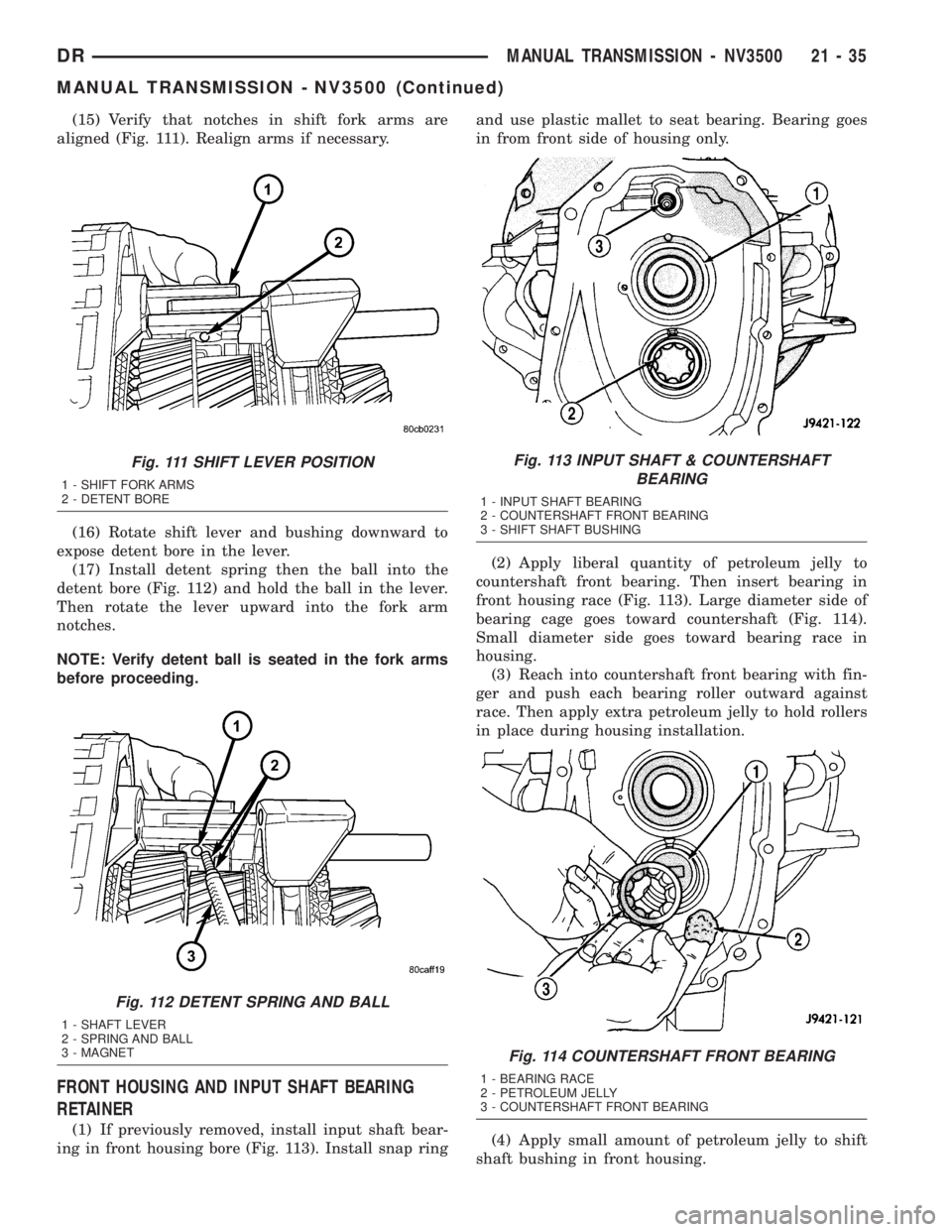
(15) Verify that notches in shift fork arms are
aligned (Fig. 111). Realign arms if necessary.
(16) Rotate shift lever and bushing downward to
expose detent bore in the lever.
(17) Install detent spring then the ball into the
detent bore (Fig. 112) and hold the ball in the lever.
Then rotate the lever upward into the fork arm
notches.
NOTE: Verify detent ball is seated in the fork arms
before proceeding.
FRONT HOUSING AND INPUT SHAFT BEARING
RETAINER
(1) If previously removed, install input shaft bear-
ing in front housing bore (Fig. 113). Install snap ringand use plastic mallet to seat bearing. Bearing goes
in from front side of housing only.
(2) Apply liberal quantity of petroleum jelly to
countershaft front bearing. Then insert bearing in
front housing race (Fig. 113). Large diameter side of
bearing cage goes toward countershaft (Fig. 114).
Small diameter side goes toward bearing race in
housing.
(3) Reach into countershaft front bearing with fin-
ger and push each bearing roller outward against
race. Then apply extra petroleum jelly to hold rollers
in place during housing installation.
(4) Apply small amount of petroleum jelly to shift
shaft bushing in front housing.
Fig. 111 SHIFT LEVER POSITION
1 - SHIFT FORK ARMS
2 - DETENT BORE
Fig. 112 DETENT SPRING AND BALL
1 - SHAFT LEVER
2 - SPRING AND BALL
3 - MAGNET
Fig. 113 INPUT SHAFT & COUNTERSHAFT
BEARING
1 - INPUT SHAFT BEARING
2 - COUNTERSHAFT FRONT BEARING
3 - SHIFT SHAFT BUSHING
Fig. 114 COUNTERSHAFT FRONT BEARING
1 - BEARING RACE
2 - PETROLEUM JELLY
3 - COUNTERSHAFT FRONT BEARING
DRMANUAL TRANSMISSION - NV3500 21 - 35
MANUAL TRANSMISSION - NV3500 (Continued)
Page 1875 of 2895
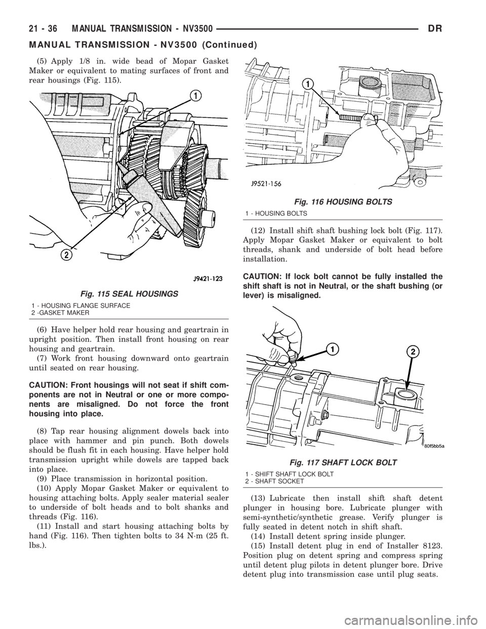
(5) Apply 1/8 in. wide bead of Mopar Gasket
Maker or equivalent to mating surfaces of front and
rear housings (Fig. 115).
(6) Have helper hold rear housing and geartrain in
upright position. Then install front housing on rear
housing and geartrain.
(7) Work front housing downward onto geartrain
until seated on rear housing.
CAUTION: Front housings will not seat if shift com-
ponents are not in Neutral or one or more compo-
nents are misaligned. Do not force the front
housing into place.
(8) Tap rear housing alignment dowels back into
place with hammer and pin punch. Both dowels
should be flush fit in each housing. Have helper hold
transmission upright while dowels are tapped back
into place.
(9) Place transmission in horizontal position.
(10) Apply Mopar Gasket Maker or equivalent to
housing attaching bolts. Apply sealer material sealer
to underside of bolt heads and to bolt shanks and
threads (Fig. 116).
(11) Install and start housing attaching bolts by
hand (Fig. 116). Then tighten bolts to 34 N´m (25 ft.
lbs.).(12) Install shift shaft bushing lock bolt (Fig. 117).
Apply Mopar Gasket Maker or equivalent to bolt
threads, shank and underside of bolt head before
installation.
CAUTION: If lock bolt cannot be fully installed the
shift shaft is not in Neutral, or the shaft bushing (or
lever) is misaligned.
(13) Lubricate then install shift shaft detent
plunger in housing bore. Lubricate plunger with
semi-synthetic/synthetic grease. Verify plunger is
fully seated in detent notch in shift shaft.
(14) Install detent spring inside plunger.
(15) Install detent plug in end of Installer 8123.
Position plug on detent spring and compress spring
until detent plug pilots in detent plunger bore. Drive
detent plug into transmission case until plug seats.
Fig. 115 SEAL HOUSINGS
1 - HOUSING FLANGE SURFACE
2 -GASKET MAKER
Fig. 116 HOUSING BOLTS
1 - HOUSING BOLTS
Fig. 117 SHAFT LOCK BOLT
1 - SHIFT SHAFT LOCK BOLT
2 - SHAFT SOCKET
21 - 36 MANUAL TRANSMISSION - NV3500DR
MANUAL TRANSMISSION - NV3500 (Continued)
Page 1917 of 2895
²release fork ball stud.
²propeller shaft slip yoke.
(2) Apply sealer to threads of bottom PTO cover
bolt and install bolt in case.
(3) Mount transmission on jack and position trans-
mission under vehicle.
(4) Raise transmission until input shaft is centered
in release bearing and clutch disc hub.
(5) Move transmission forward and start input
shaft in release bearing, clutch disc and pilot bush-
ing.
(6) Work transmission forward until seated against
clutch housing. Do not allow transmission to remain
unsupported after input shaft has entered clutch
disc.
(7) Install transmission bolts and tighten to 108
N´m (80 ft. lbs.).
(8) Install transmission mount on transmission or
rear crossmember.
(9) Install rear crossmember.
(10) Remove transmission jack and engine support
fixture.
(11) Position transmission harness wires in clips
on shift cover.
(12) Install clutch slave cylinder and install slave
cylinder shield, if equipped.
(13) Connect speed sensor and backup light switch
wires.
TWO WHEEL DRIVE
(1) Fill transmission with recommended lubricant.
Correct fill level is bottom edge of fill plug hole.
(2) Align and install propeller shaft.
(3) Lower vehicle.
(4) Clean the mating surfaces of shift tower, isola-
tor plate and shift cover with suitable wax and
grease remover.
(5) Apply Mopar Gasket Maker or equivalent to
the sealing surface of the shift cover. Do not over
apply sealant.
(6) Install the isolator plate onto the shift cover,
metal side down.
(7) Install the shift tower onto the isolator plate.
No sealant is necessary between the shift tower and
the isolator plate.
(8) Verify that the shift tower, isolator plate and
the shift tower bushings are properly aligned.
(9) Install the bolts to hold the shift tower to the
isolator plate and the shift cover. Tighten the shift
tower bolts to 10.2-11.25 N´m (7.5-8.3 ft. lbs.).
(10) Install the shift lever extension onto the shift
tower and lever assembly.
(11) Install shift boot and bezel.
(12) Connect battery negative cable.
FOUR WHEEL DRIVE
(1) Install transfer case shift mechanism on trans-
mission.
(2) Install transfer case on transmission jack.
Secure transfer case to jack with safety chains.
(3) Raise jack and align transfer case input gear
with transmission mainshaft.
(4) Move transfer case forward and seat it on
adapter.
(5) Install transfer case nuts and tighten to:
²If 3/8 studs 41-47 N´m (30-35 ft. lbs.).
²If 5/16 studs 30-41 N´m (22-30 ft. lbs.).
(6) Install transfer case shift mechanism to side of
transfer case.
(7) Connect transfer case shift lever to range lever
on transfer case.
(8) Align and connect propeller shafts.
(9) Fill transmission with required lubricant.
Check lubricant level in transfer case and add lubri-
cant if necessary.
(10) Install transfer case skid plate, if equipped
and crossmember. Tighten attaching bolts/nuts to 41
N´m (30 ft. lbs.).
(11) Install exhaust system components.
(12) Lower vehicle.
(13) Clean the mating surfaces of shift tower, iso-
lator plate and shift cover with suitable wax and
grease remover.
(14) Apply Mopar Gasket Maker or equivalent to
the sealing surface of the shift cover. Do not over
apply sealant.
(15) Install the isolator plate onto the shift cover,
metal side down.
(16) Install the shift tower onto the isolator plate.
No sealant is necessary between the shift tower and
the isolator plate.
(17) Verify that the shift tower, isolator plate and
the shift tower bushings are properly aligned.
(18) Install the bolts to hold the shift tower to the
isolator plate and the shift cover. Tighten the shift
tower bolts to 10.2-11.25 N´m (7.5-8.3 ft. lbs.).
(19) Install the shift lever extension onto the shift
tower and lever assembly.
(20) Install shift lever boot and bezel.
(21) Connect battery negative cable.
21 - 78 MANUAL TRANSMISSION - NV4500DR
MANUAL TRANSMISSION - NV4500 (Continued)
Page 1918 of 2895
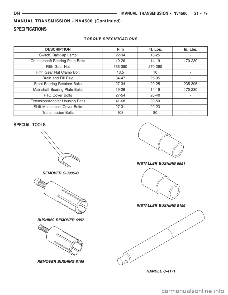
SPECIFICATIONS
TORQUE SPECIFICATIONS
DESCRIPTION N´m Ft. Lbs. In. Lbs.
Switch, Back-up Lamp 22-34 16-25 -
Countershaft Bearing Plate Bolts 19-26 14-19 170-230
Fifth Gear Nut 366-380 270-280 -
Fifth Gear Nut Clamp Bolt 13.5 10 -
Drain and Fill Plug 34-47 25-35 -
Front Bearing Retainer Bolts 27-34 20-25 235-305
Mainshaft Bearing Plate Bolts 19-26 14-19 170-230
PTO Cover Bolts 27-54 20-40 -
Extension/Adapter Housing Bolts 41-68 30-50 -
Shift Mechanism Cover Bolts 27-31 20-23 -
Transmission Bolts 108 80 -
SPECIAL TOOLS
REMOVER C-3985-B
BUSHING REMOVER 6957
REMOVER BUSHING 8155
INSTALLER BUSHING 6951
INSTALLER BUSHING 8156
HANDLE C-4171
DRMANUAL TRANSMISSION - NV4500 21 - 79
MANUAL TRANSMISSION - NV4500 (Continued)
Page 1922 of 2895
ADAPTER HOUSING SEAL
REMOVAL
(1) Raise and support vehicle.
(2) Mark the propeller shafts and yokes for instal-
lation reference and remove the shafts.
(3) Support transmission with a transmission jack.
(4) Remove engine rear support.
(5) Remove transfer case.
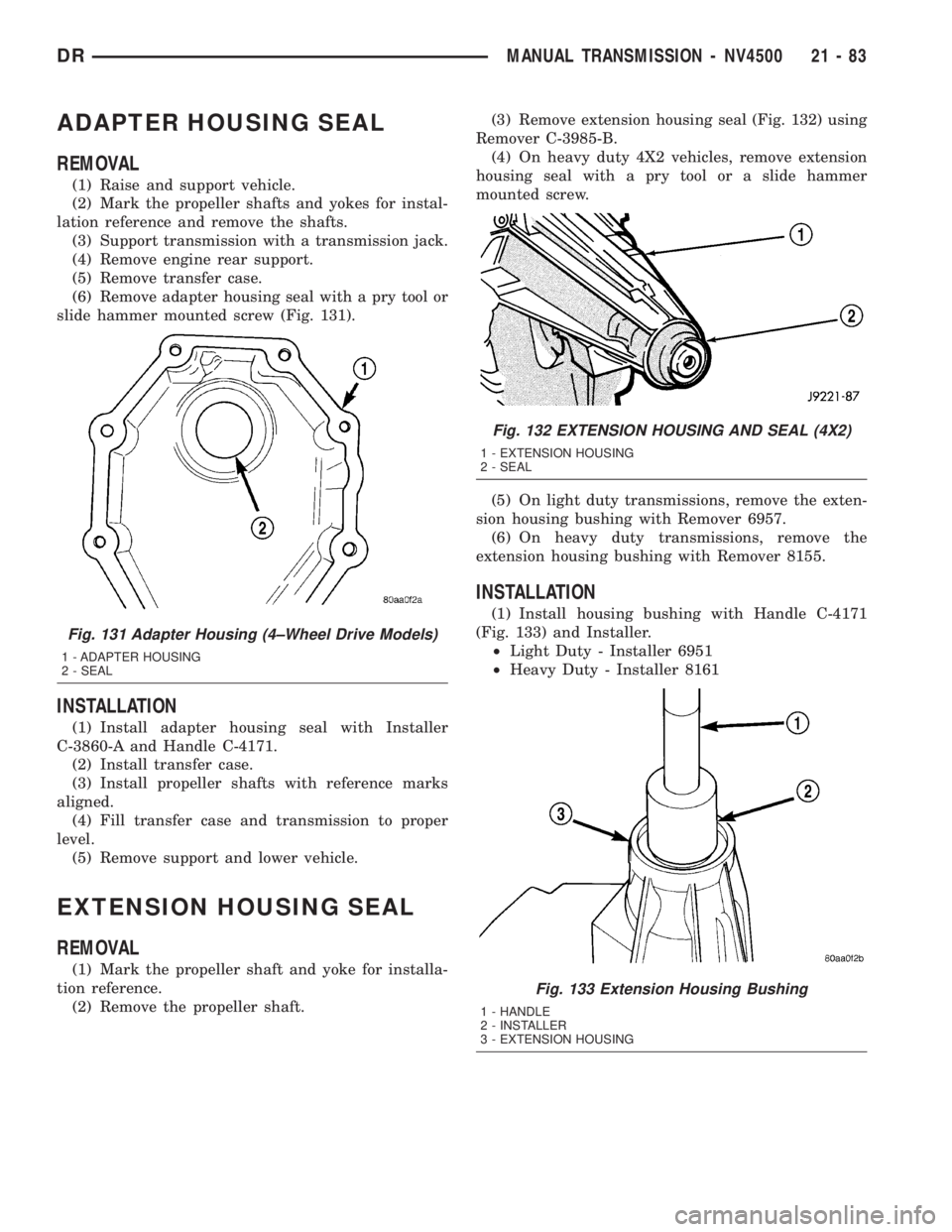
(6) Remove adapter housing seal with a pry tool or
slide hammer mounted screw (Fig. 131).
INSTALLATION
(1) Install adapter housing seal with Installer
C-3860-A and Handle C-4171.
(2) Install transfer case.
(3) Install propeller shafts with reference marks
aligned.
(4) Fill transfer case and transmission to proper
level.
(5) Remove support and lower vehicle.
EXTENSION HOUSING SEAL
REMOVAL
(1) Mark the propeller shaft and yoke for installa-
tion reference.
(2) Remove the propeller shaft.(3) Remove extension housing seal (Fig. 132) using
Remover C-3985-B.
(4) On heavy duty 4X2 vehicles, remove extension
housing seal with a pry tool or a slide hammer
mounted screw.
(5) On light duty transmissions, remove the exten-
sion housing bushing with Remover 6957.
(6) On heavy duty transmissions, remove the
extension housing bushing with Remover 8155.
INSTALLATION
(1) Install housing bushing with Handle C-4171
(Fig. 133) and Installer.
²Light Duty - Installer 6951
²Heavy Duty - Installer 8161
Fig. 131 Adapter Housing (4±Wheel Drive Models)
1 - ADAPTER HOUSING
2 - SEAL
Fig. 132 EXTENSION HOUSING AND SEAL (4X2)
1 - EXTENSION HOUSING
2 - SEAL
Fig. 133 Extension Housing Bushing
1 - HANDLE
2 - INSTALLER
3 - EXTENSION HOUSING
DRMANUAL TRANSMISSION - NV4500 21 - 83
Page 1925 of 2895
(7) Apply Mopar Lock N' Seal or equivalent to
threads of shift cover bolts.
(8) Install shift cover mechanism bolts and tighten
to 27-31 N´m (216-276 in. lbs.).
(9) Apply sealer to backup lamp switch. Install
switch into cover and tighten to 22-34 N´m (193-265
in. lbs.).
(10) Install vent assembly if removed. Apply an
adhesive/sealer to vent tube to help secure it in cover.
(11) Install transmission.
SHIFT COVER
REMOVAL
(1) Shift transmission into Neutral.
(2) Unscrew and remove the shift lever extension
from the shift
(3) Remove screws attaching shift boot to floorpan.
Then slide boot upward on the shift lever.
(4) Remove the bolts holding the shift tower to the
isolator plate and transmission shift cover.
(5) Remove the shift tower and isolator plate from
the transmission shift cover.
INSTALLATION
(1) Clean the mating surfaces of shift tower, isola-
tor plate and shift cover with suitable wax and
grease remover.
(2) Apply Mopar Gasket Maker or equivalent to
the sealing surface of the shift cover. Do not over
apply sealant.
(3) Install the isolator plate onto the shift cover,
metal side down.
(4) Install the shift tower onto the isolator plate.
No sealant is necessary between the shift tower and
the isolator plate.
(5) Verify shift tower, isolator plate and shift tower
bushings are properly aligned.
(6) Install bolts to hold the shift tower to the iso-
lator plate and the shift cover. Tighten the shift
tower bolts to 10.2-11.25 N´m (7.5-8.3 ft. lbs.).
(7) Install shift lever extension, shift boot and
bezel.
21 - 86 MANUAL TRANSMISSION - NV4500DR
SHIFT MECHANISM (Continued)
Page 1932 of 2895
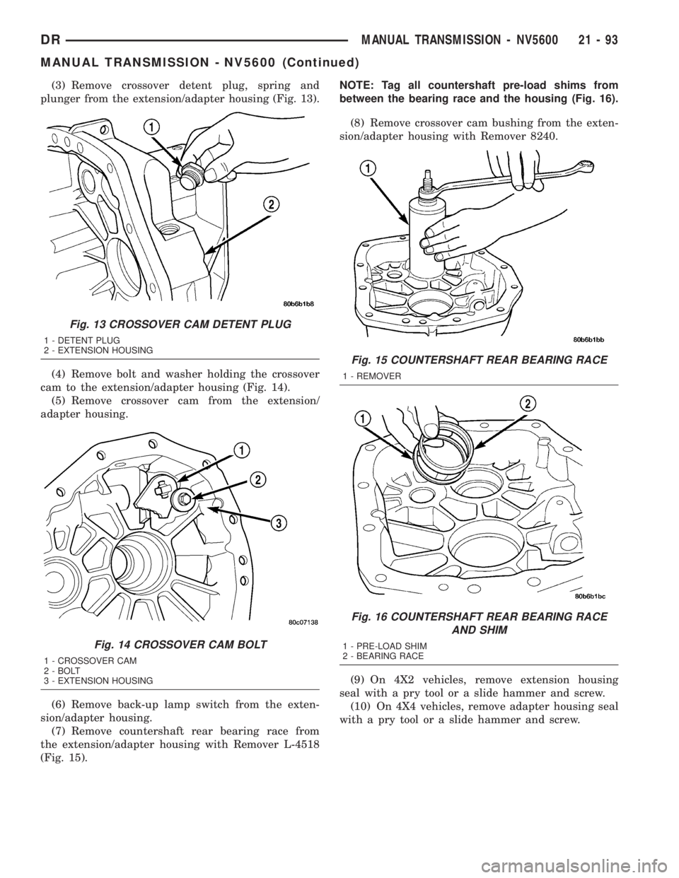
(3) Remove crossover detent plug, spring and
plunger from the extension/adapter housing (Fig. 13).
(4) Remove bolt and washer holding the crossover
cam to the extension/adapter housing (Fig. 14).
(5) Remove crossover cam from the extension/
adapter housing.
(6) Remove back-up lamp switch from the exten-
sion/adapter housing.
(7) Remove countershaft rear bearing race from
the extension/adapter housing with Remover L-4518
(Fig. 15).NOTE: Tag all countershaft pre-load shims from
between the bearing race and the housing (Fig. 16).
(8) Remove crossover cam bushing from the exten-
sion/adapter housing with Remover 8240.
(9) On 4X2 vehicles, remove extension housing
seal with a pry tool or a slide hammer and screw.
(10) On 4X4 vehicles, remove adapter housing seal
with a pry tool or a slide hammer and screw.
Fig. 13 CROSSOVER CAM DETENT PLUG
1 - DETENT PLUG
2 - EXTENSION HOUSING
Fig. 14 CROSSOVER CAM BOLT
1 - CROSSOVER CAM
2 - BOLT
3 - EXTENSION HOUSING
Fig. 15 COUNTERSHAFT REAR BEARING RACE
1 - REMOVER
Fig. 16 COUNTERSHAFT REAR BEARING RACE
AND SHIM
1 - PRE-LOAD SHIM
2 - BEARING RACE
DRMANUAL TRANSMISSION - NV5600 21 - 93
MANUAL TRANSMISSION - NV5600 (Continued)