DODGE RAM 2003 Service Manual PDF
Manufacturer: DODGE, Model Year: 2003, Model line: RAM, Model: DODGE RAM 2003Pages: 2895, PDF Size: 83.15 MB
Page 71 of 2895
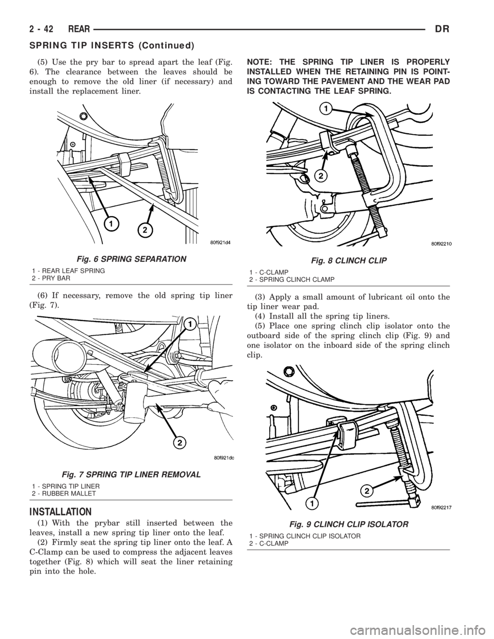
(5) Use the pry bar to spread apart the leaf (Fig.
6). The clearance between the leaves should be
enough to remove the old liner (if necessary) and
install the replacement liner.
(6) If necessary, remove the old spring tip liner
(Fig. 7).
INSTALLATION
(1) With the prybar still inserted between the
leaves, install a new spring tip liner onto the leaf.
(2) Firmly seat the spring tip liner onto the leaf. A
C-Clamp can be used to compress the adjacent leaves
together (Fig. 8) which will seat the liner retaining
pin into the hole.NOTE: THE SPRING TIP LINER IS PROPERLY
INSTALLED WHEN THE RETAINING PIN IS POINT-
ING TOWARD THE PAVEMENT AND THE WEAR PAD
IS CONTACTING THE LEAF SPRING.
(3) Apply a small amount of lubricant oil onto the
tip liner wear pad.
(4) Install all the spring tip liners.
(5) Place one spring clinch clip isolator onto the
outboard side of the spring clinch clip (Fig. 9) and
one isolator on the inboard side of the spring clinch
clip.
Fig. 6 SPRING SEPARATION
1 - REAR LEAF SPRING
2-PRYBAR
Fig. 7 SPRING TIP LINER REMOVAL
1 - SPRING TIP LINER
2 - RUBBER MALLET
Fig. 8 CLINCH CLIP
1 - C-CLAMP
2 - SPRING CLINCH CLAMP
Fig. 9 CLINCH CLIP ISOLATOR
1 - SPRING CLINCH CLIP ISOLATOR
2 - C-CLAMP
2 - 42 REARDR
SPRING TIP INSERTS (Continued)
Page 72 of 2895
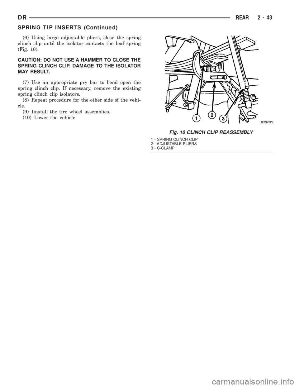
(6) Using large adjustable pliers, close the spring
clinch clip until the isolator contacts the leaf spring
(Fig. 10).
CAUTION: DO NOT USE A HAMMER TO CLOSE THE
SPRING CLINCH CLIP. DAMAGE TO THE ISOLATOR
MAY RESULT.
(7) Use an appropriate pry bar to bend open the
spring clinch clip. If necessary, remove the existing
spring clinch clip isolators.
(8) Repeat procedure for the other side of the vehi-
cle.
(9) Iinstall the tire wheel assemblies.
(10) Lower the vehicle.
Fig. 10 CLINCH CLIP REASSEMBLY
1 - SPRING CLINCH CLIP
2 - ADJUSTABLE PLIERS
3 - C-CLAMP
DRREAR 2 - 43
SPRING TIP INSERTS (Continued)
Page 73 of 2895

Page 74 of 2895
DIFFERENTIAL & DRIVELINE
TABLE OF CONTENTS
page page
PROPELLER SHAFT......................1
HALF SHAFT...........................11
FRONT AXLE - C205F....................18
FRONT AXLE - 9 1/4 AA...................45REAR AXLE-91/4.......................69
REAR AXLE - 10 1/2 AA..................100
REAR AXLE - 11 1/2 AA..................127
PROPELLER SHAFT
TABLE OF CONTENTS
page page
PROPELLER SHAFT
DIAGNOSIS AND TESTING................1
STANDARD PROCEDURE.................3
SPECIFICATIONS........................6
SPECIAL TOOLS........................6
FRONT PROPELLER SHAFT
REMOVAL.............................6
INSTALLATION..........................7
REAR PROPELLER SHAFT
REMOVAL.............................7INSTALLATION..........................8
CENTER BEARING
REMOVAL.............................8
INSTALLATION..........................8
ADJUSTMENTS.........................8
SINGLE CARDAN UNIVERSAL JOINTS
DISASSEMBLY..........................9
ASSEMBLY.............................9
PROPELLER SHAFT
DIAGNOSIS AND TESTING
PROPELLER SHAFT VIBRATION
Tires that are out-of-round or wheels that are
unbalanced, will cause a low frequency vibration.
Brake drums that are unbalanced will cause a
harsh, low frequency vibration.Driveline vibration can also result from loose or
damaged engine mounts.
Propeller shaft vibration increases as the vehicle
speed is increased. A vibration that occurs within a
specific speed range is not usually caused by a pro-
peller shaft being unbalanced. Defective universal
joints or an incorrect propeller shaft angle are usu-
ally the cause of such a vibration.
DRDIFFERENTIAL & DRIVELINE 3 - 1
Page 75 of 2895
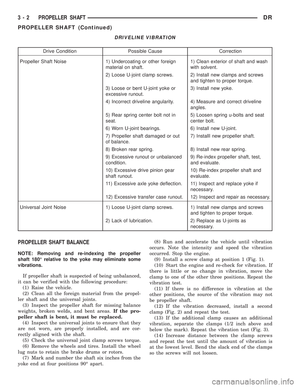
DRIVELINE VIBRATION
Drive Condition Possible Cause Correction
Propeller Shaft Noise 1) Undercoating or other foreign
material on shaft.1) Clean exterior of shaft and wash
with solvent.
2) Loose U-joint clamp screws. 2) Install new clamps and screws
and tighten to proper torque.
3) Loose or bent U-joint yoke or
excessive runout.3) Install new yoke.
4) Incorrect driveline angularity. 4) Measure and correct driveline
angles.
5) Rear spring center bolt not in
seat.5) Loosen spring u-bolts and seat
center bolt.
6) Worn U-joint bearings. 6) Install new U-joint.
7) Propeller shaft damaged or out
of balance.7) Installl new propeller shaft.
8) Broken rear spring. 8) Install new rear spring.
9) Excessive runout or unbalanced
condition.9) Re-index propeller shaft, test,
and evaluate.
10) Excessive drive pinion gear
shaft runout.10) Re-index propeller shaft and
evaluate.
11) Excessive axle yoke deflection. 11) Inspect and replace yoke if
necessary.
12) Excessive transfer case runout. 12) Inspect and repair as necessary.
Universal Joint Noise 1) Loose U-joint clamp screws. 1) Install new clamps and screws
and tighten to proper torque.
2) Lack of lubrication. 2) Replace as U-joints as
necessary.
PROPELLER SHAFT BALANCE
NOTE: Removing and re-indexing the propeller
shaft 180É relative to the yoke may eliminate some
vibrations.
If propeller shaft is suspected of being unbalanced,
it can be verified with the following procedure:
(1) Raise the vehicle.
(2) Clean all the foreign material from the propel-
ler shaft and the universal joints.
(3) Inspect the propeller shaft for missing balance
weights, broken welds, and bent areas.If the pro-
peller shaft is bent, it must be replaced.
(4) Inspect the universal joints to ensure that they
are not worn, are properly installed, and are cor-
rectly aligned with the shaft.
(5) Check the universal joint clamp screws torque.
(6) Remove the wheels and tires. Install the wheel
lug nuts to retain the brake drums or rotors.
(7) Mark and number the shaft six inches from the
yoke end at four positions 90É apart.(8) Run and accelerate the vehicle until vibration
occurs. Note the intensity and speed the vibration
occurred. Stop the engine.
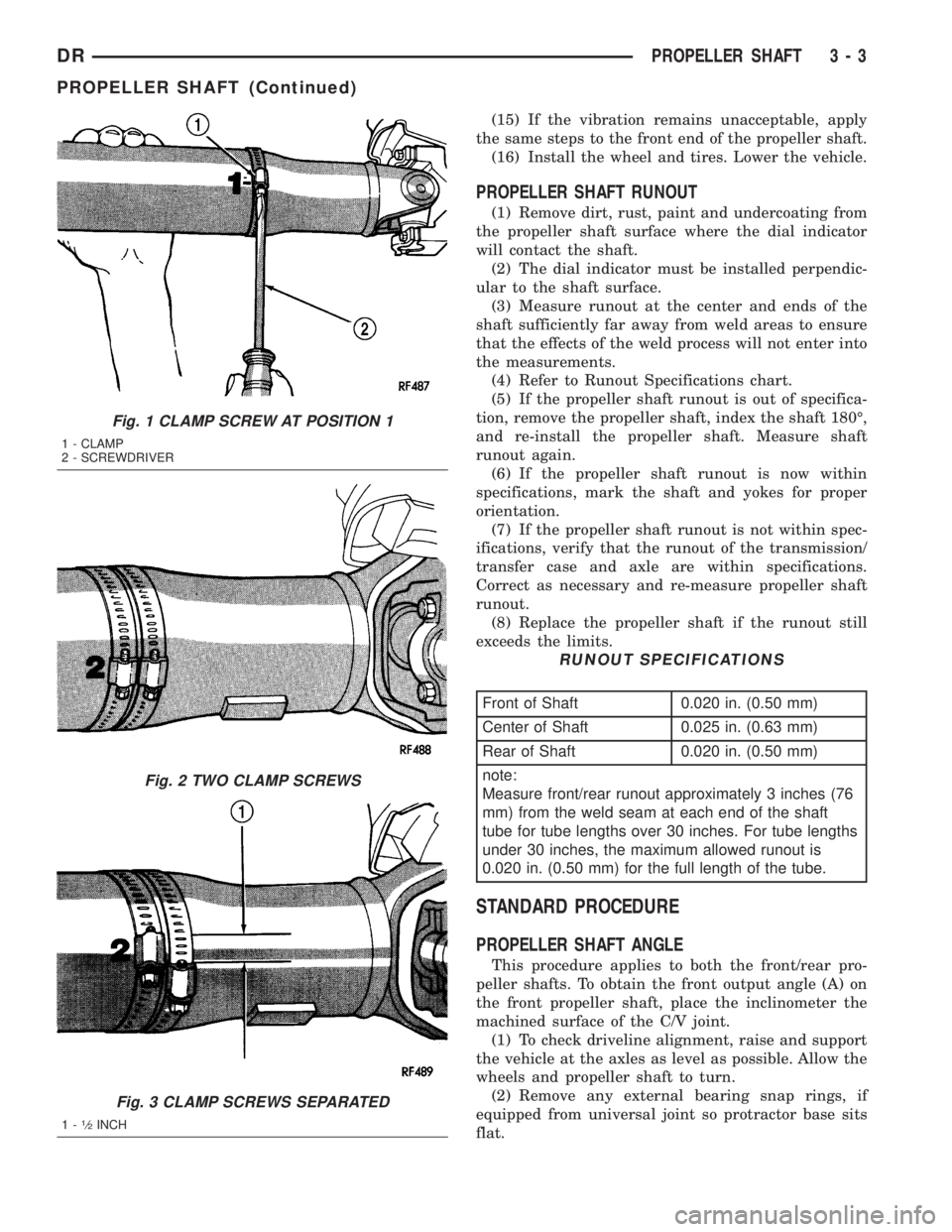
(9) Install a screw clamp at position 1 (Fig. 1).
(10) Start the engine and re-check for vibration. If
there is little or no change in vibration, move the
clamp to one of the other three positions. Repeat the
vibration test.
(11) If there is no difference in vibration at the
other positions, the source of the vibration may not
be propeller shaft.
(12) If the vibration decreased, install a second
clamp (Fig. 2) and repeat the test.
(13) If the additional clamp causes an additional
vibration, separate the clamps (1/2 inch above and
below the mark). Repeat the vibration test (Fig. 3).
(14) Increase distance between the clamp screws
and repeat the test until the amount of vibration is
at the lowest level. Bend the slack end of the clamps
so the screws will not loosen.
3 - 2 PROPELLER SHAFTDR
PROPELLER SHAFT (Continued)
Page 76 of 2895
(15) If the vibration remains unacceptable, apply
the same steps to the front end of the propeller shaft.
(16) Install the wheel and tires. Lower the vehicle.
PROPELLER SHAFT RUNOUT
(1) Remove dirt, rust, paint and undercoating from
the propeller shaft surface where the dial indicator
will contact the shaft.
(2) The dial indicator must be installed perpendic-
ular to the shaft surface.
(3) Measure runout at the center and ends of the
shaft sufficiently far away from weld areas to ensure
that the effects of the weld process will not enter into
the measurements.
(4) Refer to Runout Specifications chart.
(5) If the propeller shaft runout is out of specifica-
tion, remove the propeller shaft, index the shaft 180É,
and re-install the propeller shaft. Measure shaft
runout again.
(6) If the propeller shaft runout is now within
specifications, mark the shaft and yokes for proper
orientation.
(7) If the propeller shaft runout is not within spec-
ifications, verify that the runout of the transmission/
transfer case and axle are within specifications.
Correct as necessary and re-measure propeller shaft
runout.
(8) Replace the propeller shaft if the runout still
exceeds the limits.
RUNOUT SPECIFICATIONS
Front of Shaft 0.020 in. (0.50 mm)
Center of Shaft 0.025 in. (0.63 mm)
Rear of Shaft 0.020 in. (0.50 mm)
note:
Measure front/rear runout approximately 3 inches (76
mm) from the weld seam at each end of the shaft
tube for tube lengths over 30 inches. For tube lengths
under 30 inches, the maximum allowed runout is
0.020 in. (0.50 mm) for the full length of the tube.
STANDARD PROCEDURE
PROPELLER SHAFT ANGLE
This procedure applies to both the front/rear pro-
peller shafts. To obtain the front output angle (A) on
the front propeller shaft, place the inclinometer the
machined surface of the C/V joint.
(1) To check driveline alignment, raise and support
the vehicle at the axles as level as possible. Allow the
wheels and propeller shaft to turn.
(2) Remove any external bearing snap rings, if
equipped from universal joint so protractor base sits
flat.
Fig. 1 CLAMP SCREW AT POSITION 1
1 - CLAMP
2 - SCREWDRIVER
Fig. 2 TWO CLAMP SCREWS
Fig. 3 CLAMP SCREWS SEPARATED
1-1¤2INCH
DRPROPELLER SHAFT 3 - 3
PROPELLER SHAFT (Continued)
Page 77 of 2895
(3) Rotate the shaft until transmission/transfer
case output yoke bearing is facing downward.
NOTE: Always make measurements from front to
rear and from the same side of the vehicle.
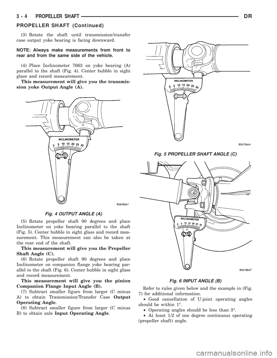
(4) Place Inclinometer 7663 on yoke bearing (A)
parallel to the shaft (Fig. 4). Center bubble in sight
glass and record measurement.
This measurement will give you the transmis-
sion yoke Output Angle (A).
(5) Rotate propeller shaft 90 degrees and place
Inclinometer on yoke bearing parallel to the shaft
(Fig. 5). Center bubble in sight glass and record mea-
surement. This measurement can also be taken at
the rear end of the shaft.
This measurement will give you the Propeller
Shaft Angle (C).
(6) Rotate propeller shaft 90 degrees and place
Inclinometer on companion flange yoke bearing par-
allel to the shaft (Fig. 6). Center bubble in sight glass
and record measurement.
This measurement will give you the pinion
Companion Flange Input Angle (B).
(7) Subtract smaller figure from larger (C minus
A) to obtain Transmission/Transfer CaseOutput
Operating Angle.
(8) Subtract smaller figure from larger (C minus
B) to obtain axleInput Operating Angle.Refer to rules given below and the example in (Fig.
7) for additional information.
²Good cancellation of U-joint operating angles
should be within 1É.
²Operating angles should be less than 3É.
²At least 1/2 of one degree continuous operating
(propeller shaft) angle.
Fig. 4 OUTPUT ANGLE (A)
Fig. 5 PROPELLER SHAFT ANGLE (C)
Fig. 6 INPUT ANGLE (B)
3 - 4 PROPELLER SHAFTDR
PROPELLER SHAFT (Continued)
Page 78 of 2895
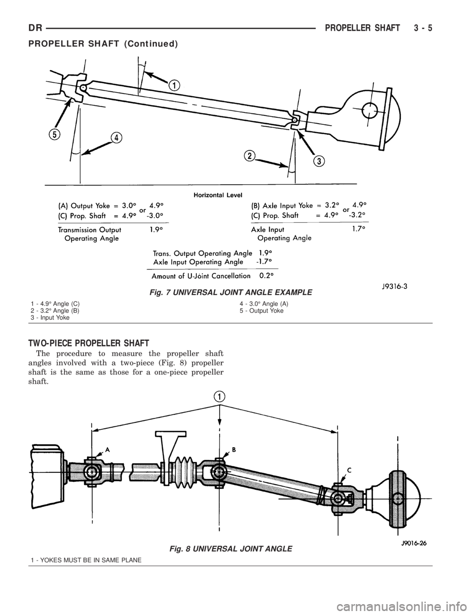
TWO-PIECE PROPELLER SHAFT
The procedure to measure the propeller shaft
angles involved with a two-piece (Fig. 8) propeller
shaft is the same as those for a one-piece propeller
shaft.
Fig. 7 UNIVERSAL JOINT ANGLE EXAMPLE
1 - 4.9É Angle (C)
2 - 3.2É Angle (B)
3 - Input Yoke4 - 3.0É Angle (A)
5 - Output Yoke
Fig. 8 UNIVERSAL JOINT ANGLE
1 - YOKES MUST BE IN SAME PLANE
DRPROPELLER SHAFT 3 - 5
PROPELLER SHAFT (Continued)
Page 79 of 2895
SPECIFICATIONS
TORQUE SPECIFICATIONS
DESCRIPTION N´m Ft. Lbs. In. Lbs.
Center Bearing Bolts 54 40 -
Front Pinion Flange Bolts 115 85 -
Rear Pinion Flange Bolts 115 85 -
SPECIAL TOOLSFRONT PROPELLER SHAFT
REMOVAL
(1) Position transmission and transfer case into
neutral.
(2) Raise and support vehicle.
(3) Remove exhaust crossover pipe.
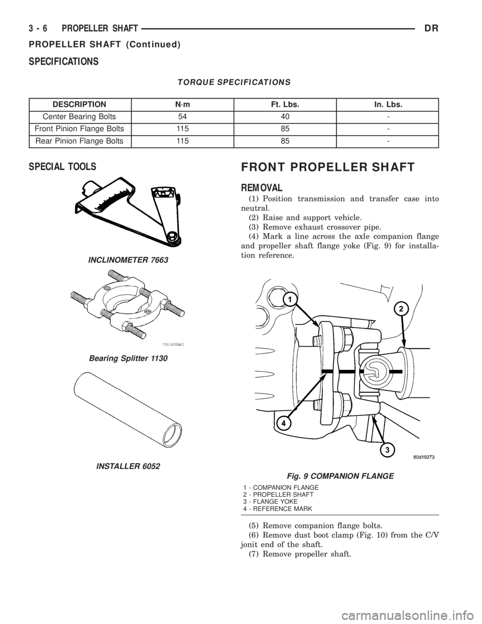
(4) Mark a line across the axle companion flange
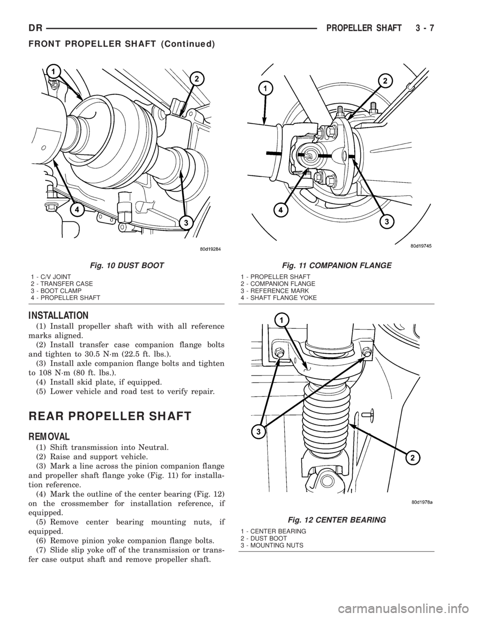
and propeller shaft flange yoke (Fig. 9) for installa-
tion reference.
(5) Remove companion flange bolts.
(6) Remove dust boot clamp (Fig. 10) from the C/V
jonit end of the shaft.
(7) Remove propeller shaft.
INCLINOMETER 7663
Bearing Splitter 1130
INSTALLER 6052
Fig. 9 COMPANION FLANGE
1 - COMPANION FLANGE
2 - PROPELLER SHAFT
3 - FLANGE YOKE
4 - REFERENCE MARK
3 - 6 PROPELLER SHAFTDR
PROPELLER SHAFT (Continued)
Page 80 of 2895
INSTALLATION
(1) Install propeller shaft with with all reference
marks aligned.
(2) Install transfer case companion flange bolts
and tighten to 30.5 N´m (22.5 ft. lbs.).
(3) Install axle companion flange bolts and tighten
to 108 N´m (80 ft. lbs.).
(4) Install skid plate, if equipped.
(5) Lower vehicle and road test to verify repair.
REAR PROPELLER SHAFT
REMOVAL
(1) Shift transmission into Neutral.
(2) Raise and support vehicle.
(3) Mark a line across the pinion companion flange
and propeller shaft flange yoke (Fig. 11) for installa-
tion reference.
(4) Mark the outline of the center bearing (Fig. 12)
on the crossmember for installation reference, if
equipped.
(5) Remove center bearing mounting nuts, if
equipped.
(6) Remove pinion yoke companion flange bolts.
(7) Slide slip yoke off of the transmission or trans-
fer case output shaft and remove propeller shaft.
Fig. 10 DUST BOOT
1 - C/V JOINT
2 - TRANSFER CASE
3 - BOOT CLAMP
4 - PROPELLER SHAFT
Fig. 11 COMPANION FLANGE
1 - PROPELLER SHAFT
2 - COMPANION FLANGE
3 - REFERENCE MARK
4 - SHAFT FLANGE YOKE
Fig. 12 CENTER BEARING
1 - CENTER BEARING
2 - DUST BOOT
3 - MOUNTING NUTS
DRPROPELLER SHAFT 3 - 7
FRONT PROPELLER SHAFT (Continued)