radiator DODGE RAM SRT-10 2006 Service Workshop Manual
[x] Cancel search | Manufacturer: DODGE, Model Year: 2006, Model line: RAM SRT-10, Model: DODGE RAM SRT-10 2006Pages: 5267, PDF Size: 68.7 MB
Page 1933 of 5267
CYLINDER HEAD
DESCRIPTION
The cylinder head is constructed of cast iron and is a one piece cross flow design with four valves per cylinder. The
arrangement of two intake and two exhaust valves per cylinder allows for a centrally located injector. The cylinder
head also includes an integral intake manifold, an integral thermostat housing, and a longitudal fuel return rifle,
which exits at the rear of the head. The 24 valve design also includes integrally cast valve guides and hardened
intake and exhaust valve seat inserts.
REMOVAL
1. Disconnect battery negative cables.
2. Raise vehicle on hoist.
3. Drain engine coolant.
4. Disconnect exhaust pipe from turbocharger elbow.
5. Remove turbocharger drain tube bolts at turbocharger. Cap off ports to prevent dirt or foreign material from enter-
ing.
6. Lower vehicle.
7. Disconnect air inlet temperature/pressure sensor.
8. Remove air cleaner housing and snorkel from the vehicle. Cap off turbocharger air inlet to prevent intrusion of
dirt or foreign material.
9. Disconnect cab heater core supply and return hoses from the cylinder head and heater pipe.
10. Disconnect turbocharger oil supply line at the turbocharger end. Cap off open ports to prevent intrusion of dirt
or foreign material.
11. Remove exhaust manifold-to-cylinder head bolts, spacers, heat shield, retention straps, and cab heater plumb-
ing. Remove exhaust manifold and turbocharger from the vehicle as an assembly.
12. Remove cooling fan/drive/shroud assembly. (Refer to 7 - COOLING/ENGINE/RADIATOR FAN - REMOVAL)
13. Remove accessory drive belt (Refer to 7 - COOLING/ACCESSORY DRIVE/DRIVE BELTS - REMOVAL).
14. Remove cooling fan support from cylinder block.
15. Remove upper generator bolt, loosen lower generator bolt, and rotate generator away from cylinder head.
16. Disconnect radiator upper hose from the thermostat housing.
17. Disconnect the Intake Air Temperature/Manifold Air Pressure, and Coolant Temperature sensor connectors.
18. Remove the engine harness to cylinder head attaching bolts and P-clipsat front of head.
19. Remove the intake air grid heater wires from the grid heater.
20. Remove engine oil level indicator tube attaching bolt at fuel filter housing bracket and inlet air connection..
21. Remove the charge air cooler-to-air inlet housing pipe.
22. Remove the engine wire harness attaching bolt and wire harness push-infastener from air inlet housing.
23. Remove the air inlet housing and intake grid heater from the intake manifold cover.
24. Remove the two grid heater harness-to-cylinder head attaching bolts at front of cylinder head.
NOTE: Extreme care should be used to keep dirt/debris from entering the fuel lines. Plastic caps should be
used on the ends of the fuel lines.
25.Remove the high pressure pump to fuel rail fuel line as follows:
a. Loosen fuel line nuts at fuel pump and at fuel rail.
b. Use a back-up wrench on the fitting at the fuel pump to keep it from loosening.
26. Remove the fuel rail to cylinder head fuel lines as follows:
a. Loosen No. 6 high pressure fuel line shield and position out of way.
b. Loosen the fuel line nuts at the fuel rail and at the cylinder head. Use a back-up wrench on HPC nut.
c. Remove the fuel line bracket bolts at the intake manifold cover.
Page 1939 of 5267
d. Install fuel line brace bolts-to-intake manifold finger tight for fuellines#2thru#5.
e. Install fuel line brace nut to rear lift bracket stud, finger tight, for fuel line #6.
f. Hand tighten fuel pump to fuel rail line.
g. Torque fuel line nuts at cylinder head to 30 Nꞏm ( 22 ft. lbs.).
h. Torque fuel line nuts at fuel rail to 30 Nꞏm (22 ft. lbs.)
i. Usingabackupwrench,torquefuelpumptofuelraillineto37Nꞏm(27ft.lbs.). At injection pump.
j. Torque fuel pump to fuel rail line to 37 Nꞏm (27 ft. lbs.) at fuel rail.
k. Torque fuel drain banjo bolt at pressure limiting valve and front of fuelfilter housing to 24 Nꞏm (18 ft. lbs.).
l. Torque fuel line brace bolts to 24 Nꞏm (18 ft. lbs.).
m. Torque fuel line brace nut to 24 Nꞏm (18 ft. lbs.).
n. Torque rail bolts to 24 Nꞏm (18 ft. lbs.).
o. Connect fuel pressure sensor.
p. Torque fuel filter mounting bolts to 24 Nꞏm (18 ft. lbs.).
19. Reposition number 6 fuel line shield and torque to 43 Nꞏm (32 ft. lbs.).
20. Install the fuel filter to injection pump low pressure line. Inspect and replace sealing washers if necessary.
Torque banjo bolts to 24 Nꞏm (18 ft. lbs.).
21. Connect fuel return line at back of cylinder head hand tight.
22. Connect fuel return line at filter housing hand tight.
23. Torque banjo connections at cylinder head and fuel filter housing to 24Nꞏm (18 ft. lbs.)
24. Install bracket to rear of filter housing. Torque to 24 Nꞏm (18 ft. lbs.).
25. Using new gaskets, install the intake grid heater and air inlet housing. Torque bolts to 24 Nꞏm (18 ft. lbs.).
26. Install wire harness P-clip and push on clip to air inlet housing.
27. Connect engine oil level indicator tube at fuel filter housing and at air inlet housing.
28. Install the charge air cooler-to-air inlet housing duct assembly. Torque all clamps to 11 Nꞏm (100 in. lbs.).
29. Connect intake grid heater wires.
30. Secure engine harness to front of cylinder head with bolt at four locations.
31. Connect engine coolant temperature sensor connector.
32. Connect radiator upper hose to thermostat housing.
33. Rotate generator into position. Install upper bolt and torque upper and lower bolts.
34. Install wire harness push-on clip below bracket.
35. Install wire harness P-clip to top of bracket.
36. Install fan support and torque to 32 Nꞏm (24 ft. lbs.).
37. Install cooling fan/drive refer to (Refer to 7 - COOLING/ENGINE/RADIATOR FAN - INSTALLATION).
38. Install accessory drive belt (Refer to 7 - COOLING/ACCESSORY DRIVE/DRIVE BELTS - INSTALLATION).
39. Install exhaust manifold/turbocharger assembly, using new gaskets.Start all bolts/spacers by hand. Starting
from the center bolts out, Torque bolts to 43 Nꞏm (32 ft. lbs.), then retorque from the center out again.
40. Install exhaust manifold heat shield to exhaust manifold studs. Install retaining nuts.Torque to 24 Nꞏm (18 ft.
lbs.).
41. Install exhaust bolt retention straps across cylinders 5 & 6.
42. Using a new gasket, connect the turbocharger oil drain tube. Torque to 24Nꞏm(18ft.lbs.).
43. Perform the turbocharger pre-lube procedure. (Refer to 11 - EXHAUST SYSTEM/TURBOCHARGER SYSTEM/
TURBOCHARGER - INSTALLATION)
44. Connect the turbocharger oil supply line. Torque to 24 Nꞏm (18 ft. lbs.).
45. Install air cleaner housing and duct.
46. Connect air inlet temperature/pressure sensor.
47. Raise vehicle on hoist.
Page 1966 of 5267
CAMSHAFT & BEARINGS (IN BLOCK)
REMOVAL
CAMSHAFT BEARINGS
NOTE: Measure the diameter of each bore. If the camshaft bore for the cam bushing is worn beyond the
limit, install a new service bushing. Inspect the rest of the camshaft bores for damage or excessive wear.If
the bores without a bushing are worn beyond the limit, the engine must be removed for machining and
installation of service bushings. If badly worn, replace the cylinder block.
1. Remove the camshaft (Refer to 9 - ENGINE/ENGINE BLOCK/CAMSHAFT & BEARINGS (IN BLOCK) -
REMOVAL).
2. Remove the bushing from the No.1 bore.
3. Mark the cylinder block so you can align the oil hole in the cylinder blockwith the oil hole in the bushing.
CAMSHAFT
1. Disconnect both battery negative cables.
2. Recover A/C refrigerant (if A/C equipped) (Refer to 24 - HEATING & AIR CONDITIONING/PLUMBING - STAN-
DARD PROCEDURE).
3. Raise vehicle on hoist.
4. Drain engine coolant into container suitable for re-use (Refer to 7 - COOLING - STANDARD PROCEDURE).
5. Lower vehicle.
6. Remove radiator upper hose.
7. Remove viscous fan/drive/shroud assembly (Refer to 7 - COOLING/ENGINE/RADIATOR FAN - REMOVAL).
8. Disconnect the coolant recovery bottle hose from the radiator filler neck.
9. Disconnect lower radiator hose from radiator outlet.
10.Automatic Transmission models:Disconnect transmission oil cooler lines from front of radiator using Special
Tool 6931 (unless equipped with finger-release disconnect).
11. Remove radiator mounting screws and lift radiator out of engine compartment.
12. Remove upper radiator support panel.
13. If A/C equipped, disconnect A/C condenser refrigerant lines.
14. Disconnect charge air cooler piping from the cooler inlet and outlet.
15. Remove the two charge air cooler mounting bolts.
16. Remove charge air cooler (and A/C condenser if equipped) from vehicle.
17. Remove accessory drive belt (Refer to 7 - COOLING/ACCESSORY DRIVE/DRIVE BELTS - REMOVAL).
18. Remove accessory drive belt tensioner.
19. Remove the fan support/hub assembly.
20. Remove crankshaft damper and speed indicator ring (Refer to 9 - ENGINE/ENGINE BLOCK/VIBRATION
DAMPER - REMOVAL).
21. Remove the gear cover-to-housing bolts and gently pry the cover away from the housing, taking care not to mar
the sealing surfaces. Remove dust seal with cover.
22. Using Special Tool 7471–B Crankshaft Barring Tool, rotate the crankshaft to align the timing marks on the
crankshaft and the camshaft gears.
23. Remove the cylinder head cover (Refer to 9 - ENGINE/CYLINDER HEAD/CYLINDER HEAD COVER(S) -
REMOVAL).
Page 1971 of 5267
12. Install gear housing cover (Refer to 9 - ENGINE/VALVE TIMING/GEAR HOUSING COVER - INSTALLATION).
Install front crankshaft dust seal.
13. Install the crankshaft damper with the speed indicator ring (Refer to 9- ENGINE/ENGINE BLOCK/VIBRATION
DAMPER - INSTALLATION).
14. Install the fan support/hub assembly Refer to (Refer to 7 - COOLING/ENGINE/RADIATOR FAN - INSTALLA-
TION).
15. Install the power steering pump.
16. Install accessory drive belt tensioner. Torque bolt to 43 Nꞏm (32 ft. lbs.).
17. Install the accessory drive belt (Refer to 7 - COOLING/ACCESSORY DRIVE/DRIVE BELTS - INSTALLATION).
18. Install the charge air cooler (with a/c condenser and auxiliary transmission oil cooler, if equipped) and tighten
the mounting bolts to 2 Nꞏm (17 in. lbs.) torque.
19. Connect charge air cooler inlet and outlet pipes. Tighten clamps to 11 Nꞏm (95 in. lbs.) torque.
20. Install the radiator upper support panel.
21. Close radiator petcock and lower the radiator into the engine compartment. Tighten the mounting bolts to 11
Nꞏm (95 in. lbs.) torque.
22. Raise vehicle on hoist.
23. Connect radiator lower hose and install clamp.
24. Connect transmission auxiliary oil cooler lines (if equipped).
25. Lower vehicle.
26. Install the fandrive/shroud assembly. (Refer to 7 - COOLING/ENGINE/RADIATOR FAN - INSTALLATION)
27. Install the coolant recovery and windshield washer fluid reservoirs to the fan shroud.
28. Connect the coolant recovery hose to the radiator filler neck.
29. Add engine coolant (Refer to 7 - COOLING - STANDARD PROCEDURE).
30. Charge A/C system with refrigerant (if A/C equipped) (Refer to 24 - HEATING & AIR CONDITIONING/PLUMB-
ING - STANDARD PROCEDURE).
31. Connect the battery negative cables.
32. Start engine and check for engine oil and coolant leaks.
Page 1976 of 5267
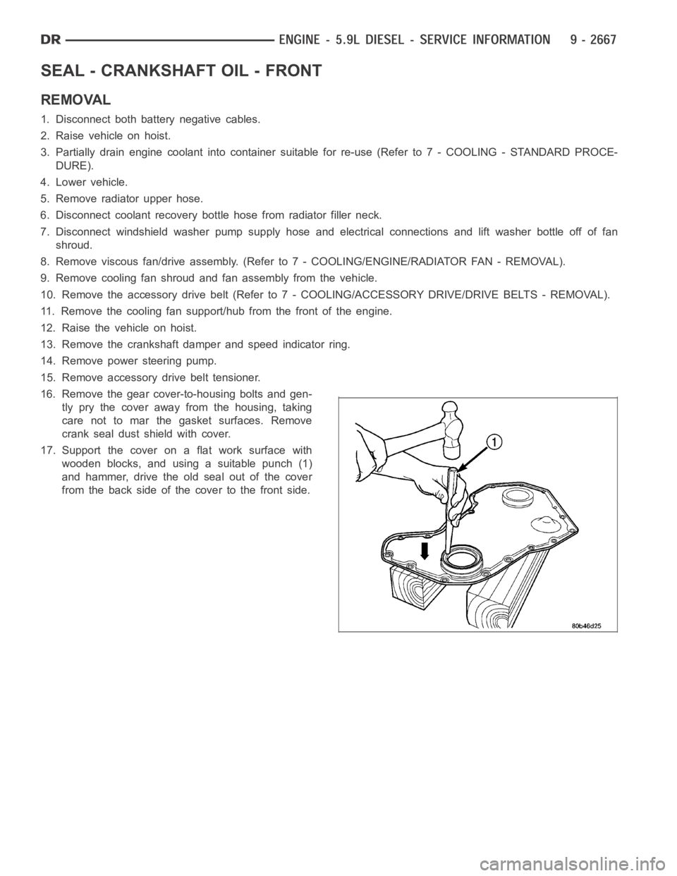
SEAL - CRANKSHAFT OIL - FRONT
REMOVAL
1. Disconnect both battery negative cables.
2. Raise vehicle on hoist.
3. Partially drain engine coolant into container suitable for re-use (Refer to 7 - COOLING - STANDARD PROCE-
DURE).
4. Lower vehicle.
5. Remove radiator upper hose.
6. Disconnect coolant recovery bottle hose from radiator filler neck.
7. Disconnect windshield washer pump supply hose and electrical connections and lift washer bottle off of fan
shroud.
8. Remove viscous fan/drive assembly. (Refer to 7 - COOLING/ENGINE/RADIATOR FAN - REMOVAL).
9. Remove cooling fan shroud and fan assembly from the vehicle.
10. Remove the accessory drive belt (Refer to 7 - COOLING/ACCESSORY DRIVE/DRIVE BELTS - REMOVAL).
11. Remove the cooling fan support/hub from the front of the engine.
12. Raisethevehicleonhoist.
13. Remove the crankshaft damper and speed indicator ring.
14. Remove power steering pump.
15. Remove accessory drive belt tensioner.
16. Remove the gear cover-to-housing bolts and gen-
tly pry the cover away from the housing, taking
care not to mar the gasket surfaces. Remove
crank seal dust shield with cover.
17. Support the cover on a flat work surface with
wooden blocks, and using a suitable punch (1)
and hammer, drive the old seal out of the cover
from the back side of the cover to the front side.
Page 1977 of 5267
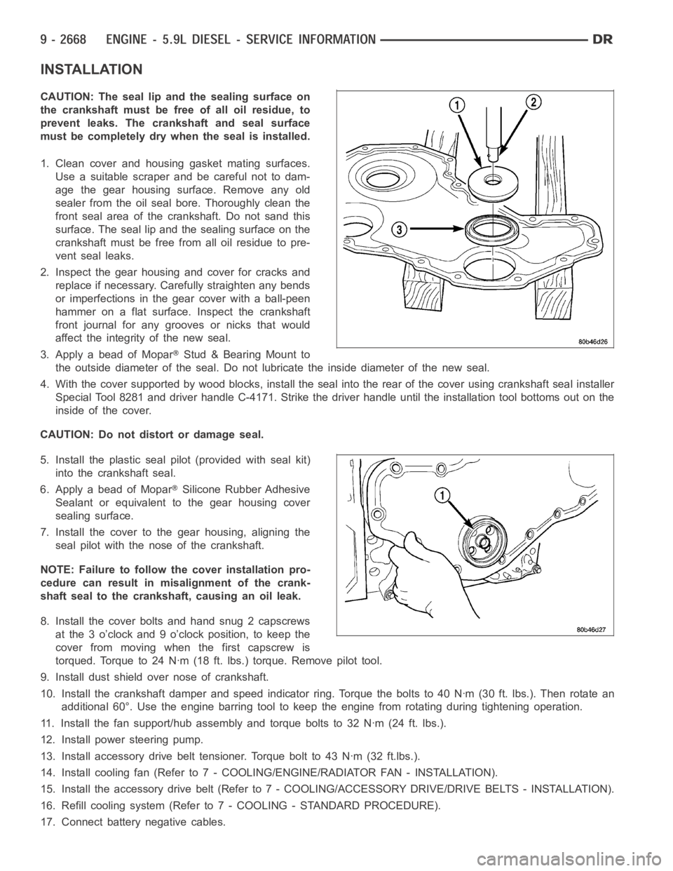
INSTALLATION
CAUTION: The seal lip and the sealing surface on
thecrankshaftmustbefreeofalloilresidue,to
prevent leaks. The crankshaft and seal surface
must be completely dry when the seal is installed.
1. Clean cover and housing gasket mating surfaces.
Use a suitable scraper and be careful not to dam-
age the gear housing surface. Remove any old
sealer from the oil seal bore. Thoroughly clean the
front seal area of the crankshaft. Do not sand this
surface. The seal lip and the sealing surface on the
crankshaft must be free from all oil residue to pre-
vent seal leaks.
2. Inspect the gear housing and cover for cracks and
replace if necessary. Carefully straighten any bends
or imperfections in the gear cover with a ball-peen
hammer on a flat surface. Inspect the crankshaft
front journal for any grooves or nicks that would
affect the integrity of the new seal.
3. Apply a bead of Mopar
Stud & Bearing Mount to
the outside diameter of the seal. Do not lubricate the inside diameter of thenewseal.
4. With the cover supported by wood blocks, install the seal into the rear ofthe cover using crankshaft seal installer
Special Tool 8281 and driver handle C-4171. Strike the driver handle untilthe installation tool bottoms out on the
inside of the cover.
CAUTION: Do not distort or damage seal.
5. Install the plastic seal pilot (provided with seal kit)
into the crankshaft seal.
6. Apply a bead of Mopar
Silicone Rubber Adhesive
Sealant or equivalent to the gear housing cover
sealing surface.
7. Install the cover to the gear housing, aligning the
seal pilot with the nose of the crankshaft.
NOTE: Failure to follow the cover installation pro-
cedure can result in misalignment of the crank-
shaft seal to the crankshaft, causing an oil leak.
8. Install the cover bolts and hand snug 2 capscrews
at the 3 o’clock and 9 o’clock position, to keep the
cover from moving when the first capscrew is
torqued. Torque to 24 Nꞏm (18 ft. lbs.) torque. Remove pilot tool.
9. Install dust shield over nose of crankshaft.
10. Install the crankshaft damper and speed indicator ring. Torque the bolts to 40 Nꞏm (30 ft. lbs.). Then rotate an
additional 60°. Use the engine barring tool to keep the engine from rotating during tightening operation.
11. Install the fan support/hub assembly and torque bolts to 32 Nꞏm (24 ft. lbs.).
12. Install power steering pump.
13. Install accessory drive belt tensioner. Torque bolt to 43 Nꞏm (32 ft.lbs.).
14. Install cooling fan (Refer to 7 - COOLING/ENGINE/RADIATOR FAN - INSTALLATION).
15. Install the accessory drive belt (Refer to 7 - COOLING/ACCESSORY DRIVE/DRIVE BELTS - INSTALLATION).
16. Refill cooling system (Refer to 7 - COOLING - STANDARD PROCEDURE).
17. Connect battery negative cables.
Page 1994 of 5267
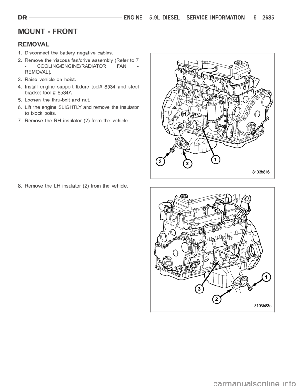
MOUNT - FRONT
REMOVAL
1. Disconnect the battery negative cables.
2. Remove the viscous fan/drive assembly (Refer to 7
- COOLING/ENGINE/RADIATOR FAN -
REMOVAL).
3. Raise vehicle on hoist.
4. Install engine support fixture tool# 8534 and steel
bracket tool # 8534A
5. Loosen the thru-bolt and nut.
6. Lift the engine SLIGHTLY and remove the insulator
to block bolts.
7. Remove the RH insulator (2) from the vehicle.
8. Remove the LH insulator (2) from the vehicle.
Page 1995 of 5267
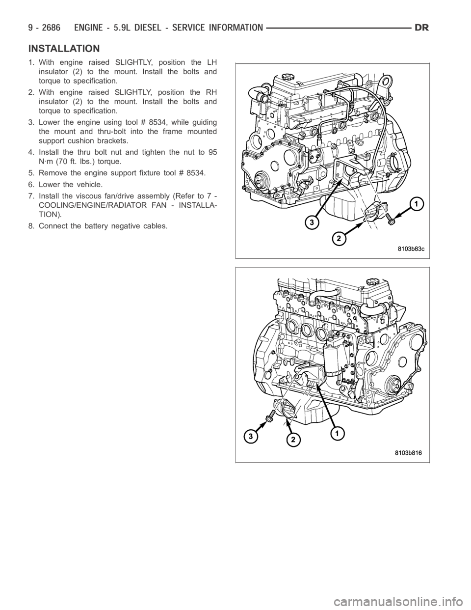
INSTALLATION
1. With engine raised SLIGHTLY, position the LH
insulator (2) to the mount. Install the bolts and
torque to specification.
2. With engine raised SLIGHTLY, position the RH
insulator (2) to the mount. Install the bolts and
torque to specification.
3. Lower the engine using tool # 8534, while guiding
the mount and thru-bolt into the frame mounted
support cushion brackets.
4. Install the thru bolt nut and tighten the nut to 95
Nꞏm (70 ft. lbs.) torque.
5. Remove the engine support fixture tool # 8534.
6. Lower the vehicle.
7. Install the viscous fan/drive assembly (Refer to 7 -
COOLING/ENGINE/RADIATOR FAN - INSTALLA-
TION).
8. Connect the battery negative cables.
Page 2008 of 5267
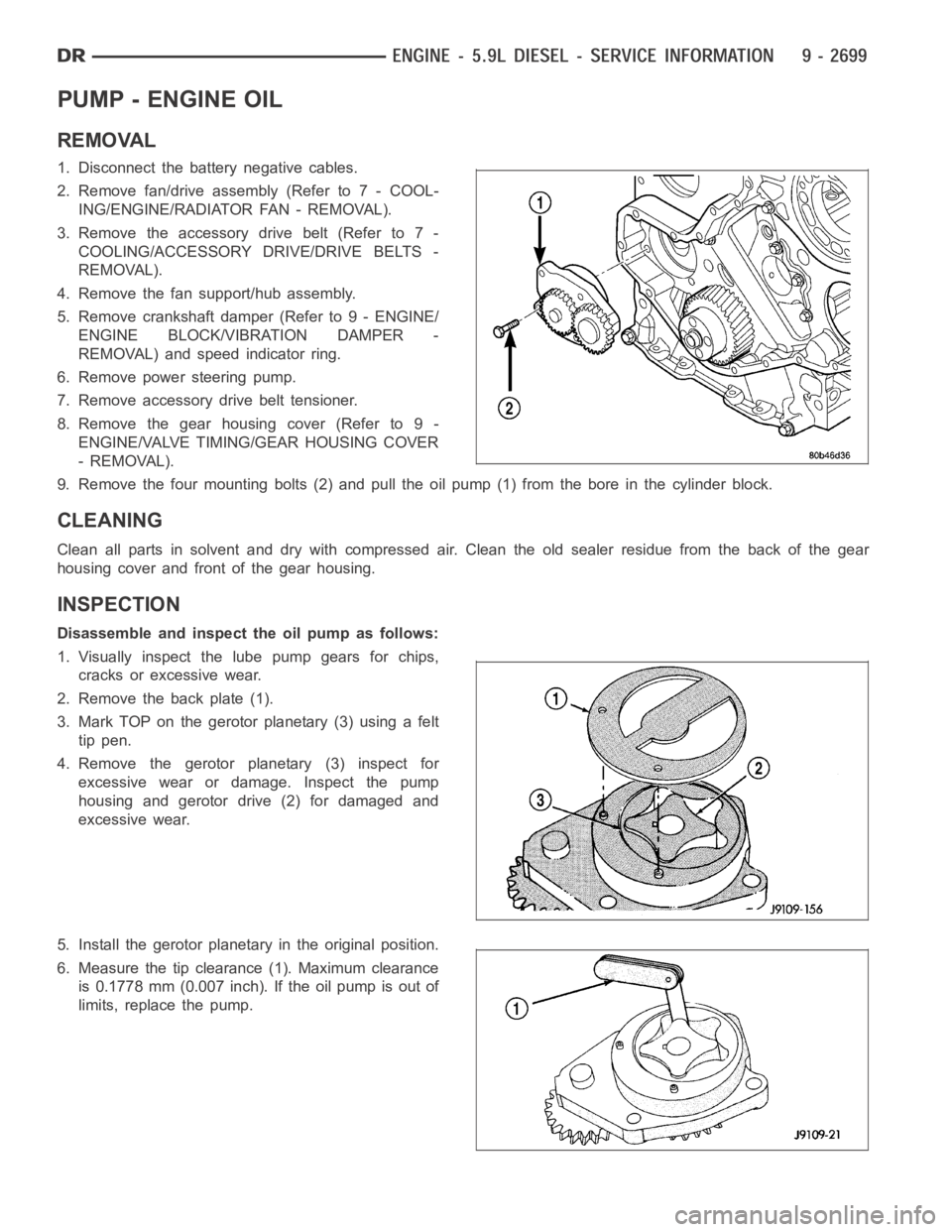
PUMP - ENGINE OIL
REMOVAL
1. Disconnect the battery negative cables.
2. Remove fan/drive assembly (Refer to 7 - COOL-
ING/ENGINE/RADIATOR FAN - REMOVAL).
3. Remove the accessory drive belt (Refer to 7 -
COOLING/ACCESSORY DRIVE/DRIVE BELTS -
REMOVAL).
4. Remove the fan support/hub assembly.
5. Remove crankshaft damper (Refer to 9 - ENGINE/
ENGINE BLOCK/VIBRATION DAMPER -
REMOVAL) and speed indicator ring.
6. Remove power steering pump.
7. Remove accessory drive belt tensioner.
8. Remove the gear housing cover (Refer to 9 -
ENGINE/VALVE TIMING/GEAR HOUSING COVER
- REMOVAL).
9. Remove the four mounting bolts (2) and pull the oil pump (1) from the bore in the cylinder block.
CLEANING
Clean all parts in solvent and dry with compressed air. Clean the old sealerresidue from the back of the gear
housing cover and front of the gear housing.
INSPECTION
Disassemble and inspect the oil pump as follows:
1. Visually inspect the lube pump gears for chips,
cracks or excessive wear.
2. Remove the back plate (1).
3. Mark TOP on the gerotor planetary (3) using a felt
tip pen.
4. Remove the gerotor planetary (3) inspect for
excessive wear or damage. Inspect the pump
housing and gerotor drive (2) for damaged and
excessive wear.
5. Install the gerotor planetary in the original position.
6. Measure the tip clearance (1). Maximum clearance
is 0.1778 mm (0.007 inch). If the oil pump is out of
limits, replace the pump.
Page 2010 of 5267
3. The back plate on the pump seats against the bot-
tom of the bore in the cylinder block. When the
pump is correctly installed, the flange on the pump
will not touch the cylinder block.
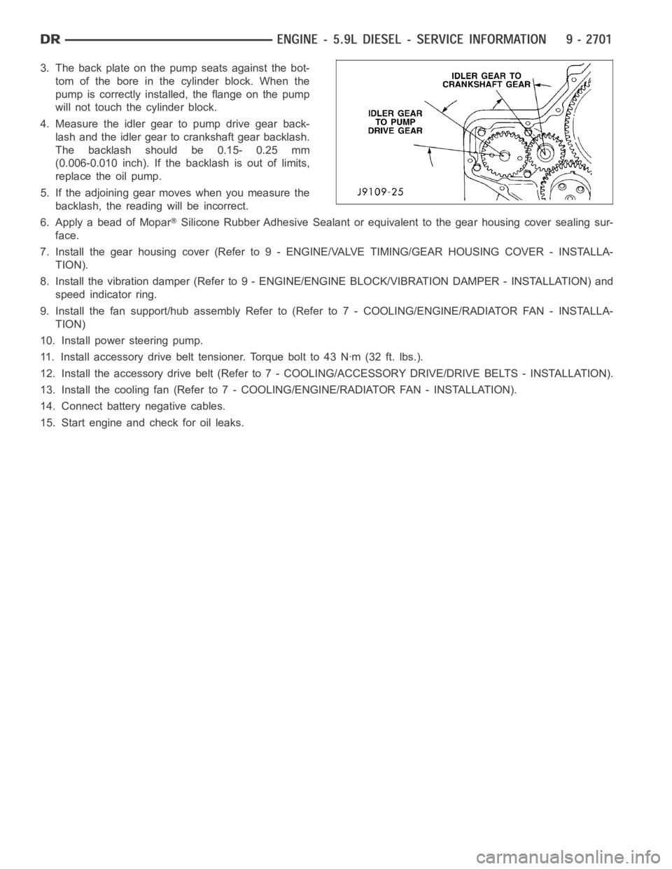
4. Measure the idler gear to pump drive gear back-
lash and the idler gear to crankshaft gear backlash.
The backlash should be 0.15- 0.25 mm
(0.006-0.010 inch). If the backlash is out of limits,
replace the oil pump.
5. If the adjoining gear moves when you measure the
backlash, the reading will be incorrect.
6. Apply a bead of Mopar
Silicone Rubber Adhesive Sealant or equivalent to the gear housing cover sealing sur-
face.
7. Install the gear housing cover (Refer to 9 - ENGINE/VALVE TIMING/GEAR HOUSING COVER - INSTALLA-
TION).
8. Install the vibration damper (Refer to 9 - ENGINE/ENGINE BLOCK/VIBRATION DAMPER - INSTALLATION) and
speed indicator ring.
9. Install the fan support/hub assemblyRefer to (Refer to 7 - COOLING/ENGINE/RADIATOR FAN - INSTALLA-
TION)
10. Install power steering pump.
11. Install accessory drive belt tensioner. Torque bolt to 43 Nꞏm (32 ft. lbs.).
12. Install the accessory drive belt (Refer to 7 - COOLING/ACCESSORY DRIVE/DRIVE BELTS - INSTALLATION).
13. Install the cooling fan (Refer to 7 - COOLING/ENGINE/RADIATOR FAN - INSTALLATION).
14. Connect battery negative cables.
15. Start engine and check for oil leaks.