relay DODGE RAM SRT-10 2006 Service Repair Manual
[x] Cancel search | Manufacturer: DODGE, Model Year: 2006, Model line: RAM SRT-10, Model: DODGE RAM SRT-10 2006Pages: 5267, PDF Size: 68.7 MB
Page 2281 of 5267
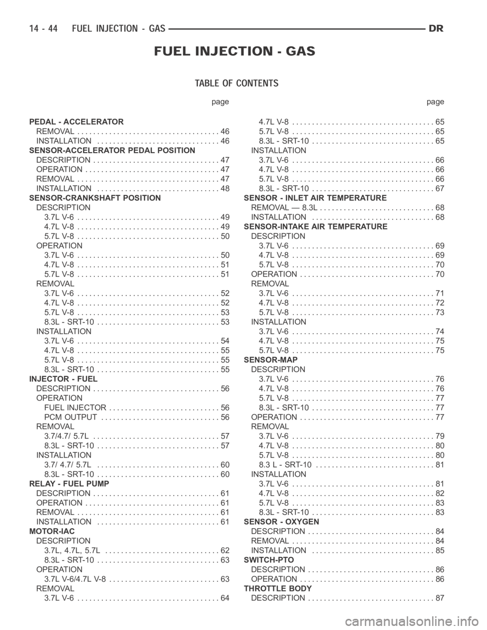
page page
PEDAL - ACCELERATOR
REMOVAL .................................... 46
INSTALLATION ............................... 46
SENSOR-ACCELERATOR PEDAL POSITION
DESCRIPTION ................................ 47
OPERATION .................................. 47
REMOVAL .................................... 47
INSTALLATION ............................... 48
SENSOR-CRANKSHAFT POSITION
DESCRIPTION
3.7L V-6 .................................... 49
4.7L V-8 .................................... 49
5.7L V-8 .................................... 50
OPERATION
3.7L V-6 .................................... 50
4.7L V-8 .................................... 51
5.7L V-8 .................................... 51
REMOVAL
3.7L V-6 .................................... 52
4.7L V-8 .................................... 52
5.7L V-8 .................................... 53
8.3L - SRT-10 ............................... 53
INSTALLATION
3.7L V-6 .................................... 54
4.7L V-8 .................................... 55
5.7L V-8 .................................... 55
8.3L - SRT-10 ............................... 55
INJECTOR - FUEL
DESCRIPTION ................................ 56
OPERATION
FUEL INJECTOR ............................ 56
PCM OUTPUT .............................. 56
REMOVAL
3.7/4.7/ 5.7L ................................ 57
8.3L - SRT-10 ............................... 57
INSTALLATION
3.7/ 4.7/ 5.7L ............................... 60
8.3L - SRT-10 ............................... 60
RELAY - FUEL PUMP
DESCRIPTION ................................ 61
OPERATION .................................. 61
REMOVAL .................................... 61
INSTALLATION ............................... 61
MOTOR-IAC
DESCRIPTION
3.7L, 4.7L, 5.7L ............................. 62
8.3L - SRT-10 ............................... 63
OPERATION
3.7L V-6/4.7L V-8 ............................ 63
REMOVAL
3.7L V-6 .................................... 644.7L V-8 .................................... 65
5.7L V-8 .................................... 65
8.3L - SRT-10 ............................... 65
INSTALLATION
3.7L V-6 .................................... 66
4.7L V-8 .................................... 66
5.7L V-8 .................................... 66
8.3L - SRT-10 ............................... 67
SENSOR - INLET AIR TEMPERATURE
REMOVAL — 8.3L ............................. 68
INSTALLATION ............................... 68
SENSOR-INTAKE AIR TEMPERATURE
DESCRIPTION
3.7L V-6 .................................... 69
4.7L V-8 .................................... 69
5.7L V-8 .................................... 70
OPERATION .................................. 70
REMOVAL
3.7L V-6 .................................... 71
4.7L V-8 .................................... 72
5.7L V-8 .................................... 73
INSTALLATION
3.7L V-6 .................................... 74
4.7L V-8 .................................... 75
5.7L V-8 .................................... 75
SENSOR-MAP
DESCRIPTION
3.7L V-6 .................................... 76
4.7L V-8 .................................... 76
5.7L V-8 .................................... 77
8.3L - SRT-10 ............................... 77
OPERATION .................................. 77
REMOVAL
3.7L V-6 .................................... 79
4.7L V-8 .................................... 80
5.7L V-8 .................................... 80
8.3 L - SRT-10 .............................. 81
INSTALLATION
3.7L V-6 .................................... 81
4.7L V-8 .................................... 82
5.7L V-8 .................................... 83
8.3L - SRT-10 ............................... 83
SENSOR - OXYGEN
DESCRIPTION ................................ 84
REMOVAL .................................... 84
INSTALLATION ............................... 85
SWITCH-PTO
DESCRIPTION ................................ 86
OPERATION .................................. 86
THROTTLE BODY
DESCRIPTION ................................ 87
Page 2293 of 5267
INJECTOR - FUEL
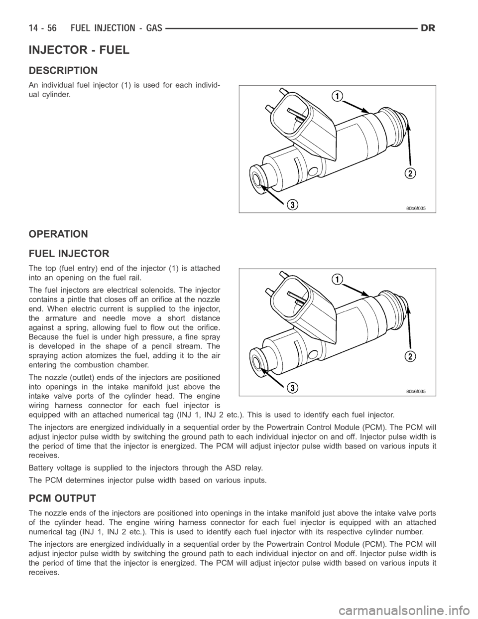
DESCRIPTION
An individual fuel injector (1) is used for each individ-
ual cylinder.
OPERATION
FUEL INJECTOR
The top (fuel entry) end of the injector (1) is attached
into an opening on the fuel rail.
The fuel injectors are electrical solenoids. The injector
contains a pintle that closes off an orifice at the nozzle
end. When electric current is supplied to the injector,
the armature and needle move a short distance
against a spring, allowing fuel to flow out the orifice.
Because the fuel is under high pressure, a fine spray
is developed in the shape of a pencil stream. The
spraying action atomizes the fuel, adding it to the air
entering the combustion chamber.
The nozzle (outlet) ends of the injectors are positioned
into openings in the intake manifold just above the
intake valve ports of the cylinder head. The engine
wiring harness connector for each fuel injector is
equipped with an attached numerical tag (INJ 1, INJ 2 etc.). This is used to identify each fuel injector.
The injectors are energized individually in a sequential order by the Powertrain Control Module (PCM). The PCM will
adjust injector pulse width by switching the ground path to each individual injector on and off. Injector pulse width is
the period of time that the injector isenergized. The PCM will adjust injector pulse width based on various inputs it
receives.
Battery voltage is supplied to the injectors through the ASD relay.
The PCM determines injector pulse width based on various inputs.
PCM OUTPUT
The nozzle ends of the injectors are positioned into openings in the intakemanifold just above the intake valve ports
of the cylinder head. The engine wiring harness connector for each fuel injector is equipped with an attached
numerical tag (INJ 1, INJ 2 etc.). This is used to identify each fuel injector with its respective cylinder number.
The injectors are energized individually in a sequential order by the Powertrain Control Module (PCM). The PCM will
adjust injector pulse width by switching the ground path to each individual injector on and off. Injector pulse width is
the period of time that the injector isenergized. The PCM will adjust injector pulse width based on various inputs it
receives.
Page 2294 of 5267
Battery voltage (12 volts +) is supplied to the injectors through the ASD relay. The ASD relay will shut-down the 12
volt power source to the fuel injectors if the PCM senses the ignition is on,but the engine is not running. This
occurs after the engine has not been running for approximately 1.8 seconds.
The PCM determines injector on-time (pulse width) based on various inputs.
REMOVAL
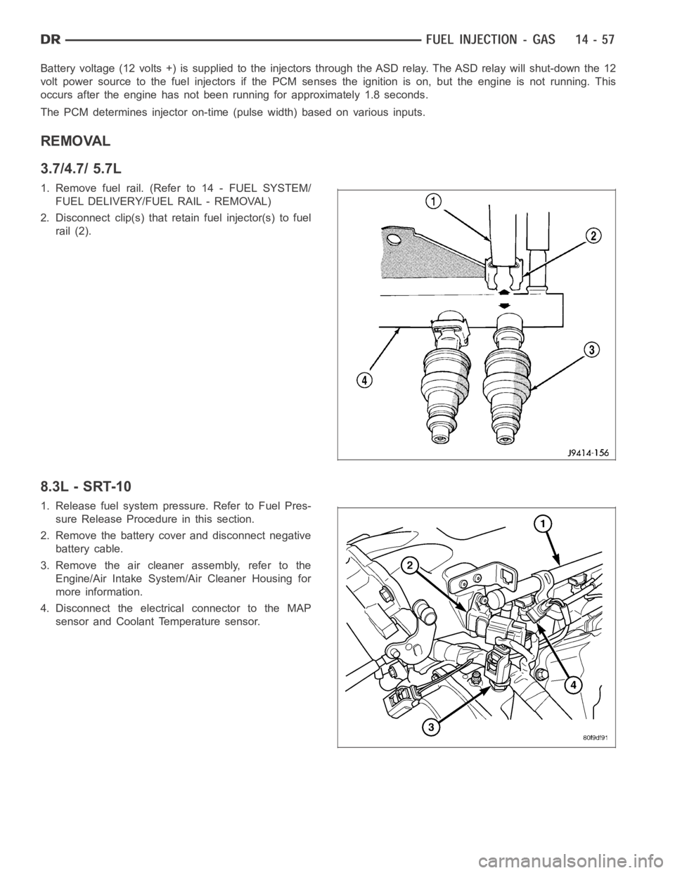
3.7/4.7/ 5.7L
1. Remove fuel rail. (Refer to 14 - FUEL SYSTEM/
FUEL DELIVERY/FUEL RAIL - REMOVAL)
2. Disconnect clip(s) that retain fuel injector(s) to fuel
rail (2).
8.3L - SRT-10
1. Release fuel system pressure. Refer to Fuel Pres-
sure Release Procedure in this section.
2. Remove the battery cover and disconnect negative
battery cable.
3. Remove the air cleaner assembly, refer to the
Engine/Air Intake System/Air Cleaner Housing for
more information.
4. Disconnect the electrical connector to the MAP
sensor and Coolant Temperature sensor.
Page 2298 of 5267
RELAY - FUEL PUMP
DESCRIPTION
The 5–pin, 12–volt, fuel pump relay is located in the Power Distribution Center (PDC). Refer to the label on the PDC
cover for relay location.
OPERATION
The Powertrain Control Module (PCM) energizes the electric fuel pump through the fuel pump relay. The fuel pump
relay is energized by first applying battery voltage to it when the ignition key is turned ON, and then applying a
ground signal to the relay from the PCM.
Whenever the ignition key is turned ON, the electric fuel pump will operate. But, the PCM will shut-down the ground
circuit to the fuel pump relay in approximately 1–3 seconds unless the engine is operating or the starter motor is
engaged.
REMOVAL
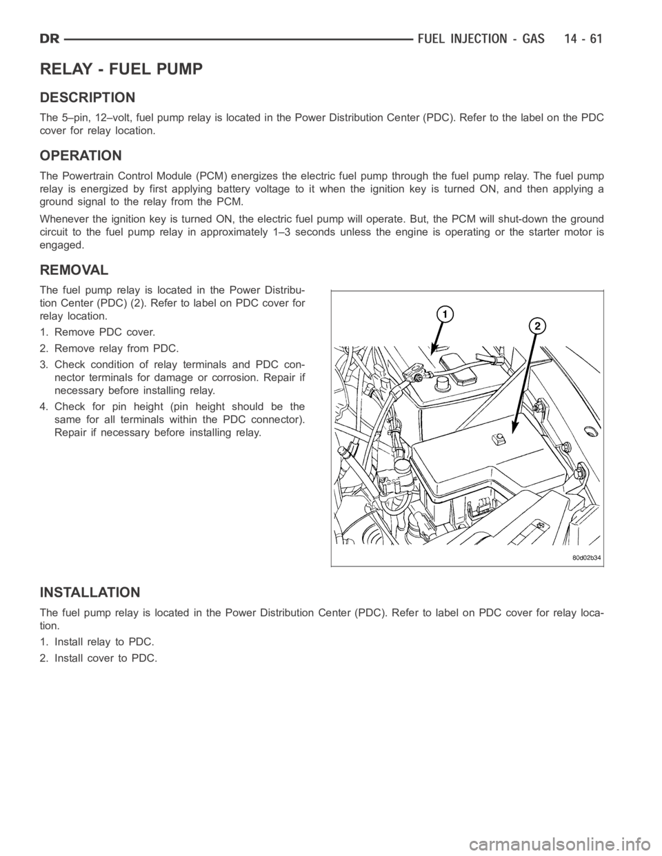
The fuel pump relay is located in the Power Distribu-
tion Center (PDC) (2). Refer to label on PDC cover for
relay location.
1. Remove PDC cover.
2. Remove relay from PDC.
3. Check condition of relay terminals and PDC con-
nector terminals for damage or corrosion. Repair if
necessary before installing relay.
4. Check for pin height (pin height should be the
same for all terminals within the PDC connector).
Repair if necessary before installing relay.
INSTALLATION
The fuel pump relay is located in the Power Distribution Center (PDC). Refer to label on PDC cover for relay loca-
tion.
1. Install relay to PDC.
2. Install cover to PDC.
Page 2342 of 5267
FUEL DELIVERY - DIESEL
DESCRIPTION - DIESEL FUEL SYSTEM
WARNING: High-pressure fuel lines deliver diesel
fuel under extreme pressure from the injection
pump to the fuel injectors. This may be as high as
160,000 kpa (23,206 psi). Use extreme caution
when inspecting for high-pressure fuel leaks.
Inspect for high-pressure fuel leaks with a sheet of
cardboard. High fuel injection pressure can cause
personal injury if contact is made with the skin.
The fuel system used on the Cummins engine is an electronically controlled, Bosch HPCR (High-Pressure Common
Rail) system. The HPCR system consists of five main components:
Electric Fuel Transfer (lift) Pump Located in the Fuel Tank
Fuel Pump/Gear Pump (attached to fuel injection pump)
High-Pressure Fuel Injection Pump
Fuel Injection Rail
Fuel Injectors
Also to be considered as part of the overall fuel system are:
Accelerator Pedal
Air Cleaner Housing/Element
Check Valve Banjo Fitting at Rear of Cylinder Head
Fuel Connector Tubes
Fuel Drain Manifold (passage)
Fuel Drain Valve (at filter)
Fuel Filter/Water Separator
Fuel Heater
Fuel Heater Relay
Fuel Transfer Pump Relay
Fuel Level (gauge) Sending Unit
Fuel Pressure Limiting Valve
Fuel Tank
Fuel Tank Module (containing a fuel gauge sending unit, separate fuel filter located at bottom of tank module,
and fuel transfer pump)
Fuel Tank Filler/Vent Tube Assembly
Fuel Tank Filler Tube Cap
Fuel Tubes/Lines/Hoses
High-Pressure Fuel Injector Lines
In-Tank Fuel Filter (at bottom of fuel tank module)
Low-Pressure Fuel Supply Lines
Low-Pressure Fuel Return Lines
Overflow Valve
Quick-Connect Fuel Line Fittings
Accelerator Pedal Position Sensor (APPS) Located in Cab
Water Draining (maintenance)
Water-In-Fuel (WIF) Sensor
Screened Banjo Bolt (22)
The fuel injection pump supplies high pressure to the fuel rail independent of engine speed. This high pressure fuel
is then accumulated in the fuel rail. High pressure fuel is constantly supplied to the injectors by the fuel rail. The
Engine Control Module (ECM) controls the fueling and timing of the engine by actuating the injectors.
Page 2352 of 5267
HEATER-FUEL
DESCRIPTION
The fuel heater assembly is located on the side of the fuel filter housing and internal to the fuel filter housing .
The heater/element assembly is equipped with a temperature sensor (thermostat) that senses fuel temperature. This
sensor is attached to the fuel heater/element assembly.
OPERATION
The fuel heater is used to prevent diesel fuel from waxing during cold weather operation.
When the fuel temperature is below 45° ±8 F (7°C), the temperature sensor allows current to flow to the heater
element warming the fuel. When the fuel temperature is above 75° ±8 F (24°C), the sensor stops current flow to the
heater element.
Battery voltage to operate the fuel heater element is supplied from the ignition switch and through a solid stated
device in the IPM.The fuel heater element and
solid state device in IPMinstead offuel heater relayare not
computer controlled.
The heater element operates on 12 volts, 300 watts at 0° F (-18° C).
DIAGNOSIS AND TESTING
FUEL HEATER
The fuel heater is used to prevent diesel fuel from waxing during cold weather operation.
NOTE: The fuel heater element,
solid state device in IPMinstead offuel heater relayand fuel heater tem-
perature sensor are not controlled by the Engine Control Module (ECM).
A malfunctioning fuel heater can cause a wax build-up in the fuel filter/water separator. Wax build-up in the filter/
separator can cause engine starting problems and prevent the engine from revving up. It can also cause blue or
white fog-like exhaust. If the heater is not operating in cold temperatures, the engine may not operate due to fuel
waxing.
The fuel heater assembly is located on the side of fuel filter housing and internal to the fuel filter housing.
The heater assembly is equipped with a built-in fuel temperature sensor (thermostat) that senses fuel temperature.
When fuel temperature drops below 45° ± 8° F (7° C), the sensor allows current to flow to built-in heater element
to warm fuel. When fuel temperature rises above 75 °± 8° F (24° C), the sensorstops current flow to heater ele-
ment (circuit is open).
Voltage to operate fuel heater element is supplied from ignition switch, through
solid state device in IPM,tofuel
temperature sensor and on to fuel heater element.
The heater element operates on 12 volts, 300 watts at 0 °F (-18° C). As temperature increases, power requirements
decrease.
A minimum of 7 volts is required to operate the fuel heater. The resistance value of the heater element is less than
1 ohm (cold) and up to 1000 ohms warm.
TESTING
1. Disconnect electrical connector from thermostat.
Ambient temperature must be below the circuit close temperature. If necessary, induce this ambient temperature by
placing ice packs on thermostat to produce an effective ambient temperature below circuit close temperature.
Measure resistance across two pins. Operating range is 0.3 - 0.45 Ohms.
2. If resistance is out of range, remove thermostat and check resistance across terminal connections of heater. The
heater can be checked at room temperature. Operating range is 0.3 - 0.45 Ohms.
3. Replace heater if resistance is not within operating range.
4. If heater is within operating range, replace heater thermostat.
Page 2373 of 5267
PUMP - FUEL TRANSFER
DESCRIPTION
The fuel transfer pump (fuel lift pump) is part of the fuel pump module. The fuel pump module is located in the fuel
tank. The 12–volt electric pump is operated and controlled by the Engine Control Module (ECM). The ECM controls
a relay in the Intelligent Power Module(IPM) for transfer pump operation.
OPERATION
The purpose of the fuel transfer pump is to supply (transfer) a low-pressure fuel source:fromthe fuel tank,through
the fuel filter/water separator andtothe fuel injection pump. Here, the low-pressure is raised to a high-pressure by
the fuel injection pump for operation of the high-pressure fuel injectors. Check valves within the pump, control direc-
tion of fuel flow and prevent fuel bleed-back during engine shut down.
Maximum current flow to the pump is 5 amperes.
With the engine running, the pump has a 100 percent duty-cycle.
The transfer pump is self-priming: When the key is first turned on (withoutcranking engine), the pump will operate
for approximately 2 seconds and then shut off (Note: When ambient temperatures are cold enough to cause the
intake air heaters to operate, the fuel lift pump will operate during the entire intake air pre-heat cycle). The pump will
also operate for up to 25 seconds after the starter is engaged, and then disengaged and the engine is not running.
The pump shuts off immediately if the key is on and the engine stops running.
The fuel volume of the transfer pump will always provide more fuel than the fuel injection pump requires. Excess
fuel is returned from the injection pump through an overflow valve, and then back to the fuel tank.
REMOVAL
The fuel transfer pump (fuel lift pump) is a part of the fuel tank module. It is not serviced separately. Refer to Fuel
Tank Module Removal or Installation for procedures (Refer to 14 - FUEL SYSTEM/FUEL DELIVERY/FUEL TANK
MODULE - REMOVAL).
INSTALLATION
The fuel transfer pump (fuel lift pump) is a part of the fuel tank module. It is not serviced separately (Refer to 14 -
FUEL SYSTEM/FUEL DELIVERY/FUEL TANK MODULE - INSTALLATION).
Page 2377 of 5267
page page
SENSOR-ACCELERATOR PEDAL POSITION
DESCRIPTION ............................... 141
OPERATION ................................. 141
REMOVAL ................................... 141
INSTALLATION .............................. 142
SENSOR-CAMSHAFT POSITION
DESCRIPTION ............................... 143
OPERATION ................................. 143
REMOVAL ................................... 143
INSTALLATION .............................. 144
SENSOR-CRANKSHAFT POSITION
DESCRIPTION ............................... 145
OPERATION ................................. 145
REMOVAL ................................... 146
INSTALLATION .............................. 146
ACTUATOR - FUEL CONTROL
DESCRIPTION ............................... 147
OPERATION ................................. 147
REMOVAL ................................... 147
INSTALLATION .............................. 147
INJECTOR - FUEL
DESCRIPTION ............................... 148
OPERATION ................................. 149
REMOVAL ................................... 149
INSTALLATION .............................. 153
FUEL INJECTOR RAIL
DESCRIPTION ............................... 155
OPERATION ................................. 155REMOVAL ................................... 155
INSTALLATION .............................. 156
SENSOR-TEMPERATURE/PRESSURE-INTAKE
DESCRIPTION ............................... 157
OPERATION ................................. 157
REMOVAL ................................... 157
INSTALLATION .............................. 159
HEATER - INTAKE AIR
DESCRIPTION ............................... 160
OPERATION ................................. 160
REMOVAL ................................... 160
INSTALLATION .............................. 162
RELAY - INTAKE AIR HEATER
DESCRIPTION ............................... 163
OPERATION ................................. 163
REMOVAL ................................... 163
INSTALLATION .............................. 164
SENSOR-TEMPERATURE/PRESSURE-MAP
DESCRIPTION ............................... 165
OPERATION ................................. 165
REMOVAL ................................... 165
INSTALLATION .............................. 166
SENSOR-MAP
DESCRIPTION ............................... 167
SWITCH - PTO
DESCRIPTION ............................... 168
OPERATION ................................. 168
Page 2397 of 5267
HEATER - INTAKE AIR
DESCRIPTION
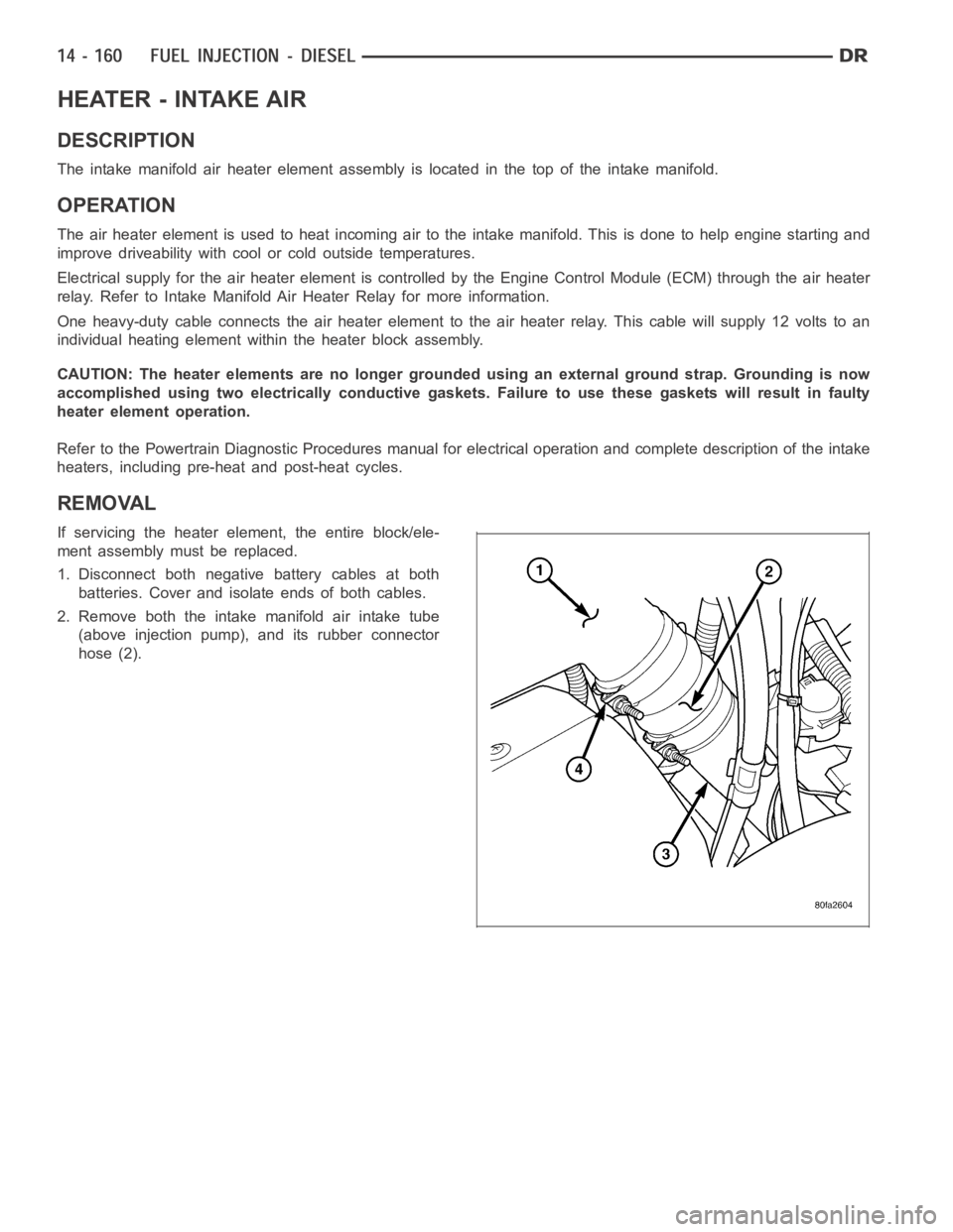
The intake manifold air heater element assembly is located in the top of theintake manifold.
OPERATION
The air heater element is used to heat incoming air to the intake manifold. This is done to help engine starting and
improve driveability with cool or cold outside temperatures.
Electrical supply for the air heater element is controlled by the Engine Control Module (ECM) through the air heater
relay. Refer to Intake Manifold Air Heater Relay for more information.
One heavy-duty cable connects the air heater element to the air heater relay. This cable will supply 12 volts to an
individual heating element within the heater block assembly.
CAUTION: The heater elements are no longer grounded using an external ground strap. Grounding is now
accomplished using two electrically conductive gaskets. Failure to use these gaskets will result in faulty
heater element operation.
Refer to the Powertrain Diagnostic Procedures manual for electrical operation and complete description of the intake
heaters, including pre-heat and post-heat cycles.
REMOVAL
If servicing the heater element, the entire block/ele-
ment assembly must be replaced.
1. Disconnect both negative battery cables at both
batteries. Cover and isolate ends of both cables.
2. Remove both the intake manifold air intake tube
(above injection pump), and its rubber connector
hose (2).
Page 2400 of 5267
RELAY - INTAKE AIR HEATER
DESCRIPTION
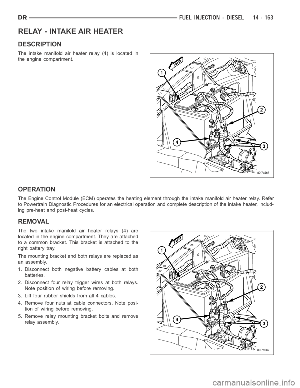
The intake manifold air heater relay (4) is located in
the engine compartment.
OPERATION
The Engine Control Module (ECM) operates the heating element through the intake manifold air heater relay. Refer
to Powertrain Diagnostic Procedures for an electrical operation and complete description of the intake heater, includ-
ing pre-heat and post-heat cycles.
REMOVAL
The two intake manifold air heater relays (4) are
located in the engine compartment. They are attached
to a common bracket. This bracket is attached to the
right battery tray.
The mounting bracket and both relays are replaced as
an assembly.
1. Disconnect both negative battery cables at both
batteries.
2. Disconnect four relay trigger wires at both relays.
Note position of wiring before removing.
3. Lift four rubber shields from all 4 cables.
4. Remove four nuts at cable connectors. Note posi-
tion of wiring before removing.
5. Remove relay mounting bracket bolts and remove
relay assembly.