relay DODGE RAM SRT-10 2006 Service Repair Manual
[x] Cancel search | Manufacturer: DODGE, Model Year: 2006, Model line: RAM SRT-10, Model: DODGE RAM SRT-10 2006Pages: 5267, PDF Size: 68.7 MB
Page 1447 of 5267
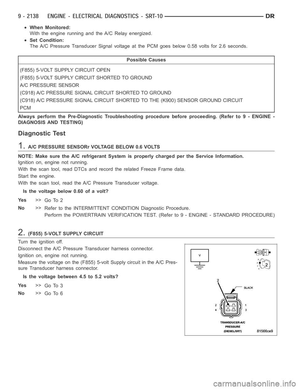
When Monitored:
With the engine running and the A/C Relay energized.
Set Condition:
The A/C Pressure Transducer Signal voltage at the PCM goes below 0.58 voltsfor 2.6 seconds.
Possible Causes
(F855) 5-VOLT SUPPLY CIRCUIT OPEN
(F855) 5-VOLT SUPPLY CIRCUIT SHORTED TO GROUND
A/C PRESSURE SENSOR
(C918) A/C PRESSURE SIGNAL CIRCUIT SHORTED TO GROUND
(C918) A/C PRESSURE SIGNAL CIRCUIT SHORTED TO THE (K900) SENSOR GROUND CIRCUIT
PCM
Always perform the Pre-Diagnostic Troubleshooting procedure before proceeding. (Refer to 9 - ENGINE -
DIAGNOSIS AND TESTING)
Diagnostic Test
1.A/C PRESSURE SENSORr VOLTAGE BELOW 0.6 VOLTS
NOTE: Make sure the A/C refrigerant System is properly charged per the Service Information.
Ignition on, engine not running.
With the scan tool, read DTCs and record the related Freeze Frame data.
Start the engine.
With the scan tool, read the A/C Pressure Transducer voltage.
Is the voltage below 0.60 of a volt?
Ye s>>
Go To 2
No>>
Refer to the INTERMITTENT CONDITION Diagnostic Procedure.
Perform the POWERTRAIN VERIFICATION TEST. (Refer to 9 - ENGINE - STANDARD PROCEDURE)
2.(F855) 5-VOLT SUPPLY CIRCUIT
Turn the ignition off.
Disconnect the A/C Pressure Transducer harness connector.
Ignition on, engine not running.
Measure the voltage on the (F855) 5-volt Supply circuit in the A/C Pres-
sure Transducer harness connector.
Is the voltage between 4.5 to 5.2 volts?
Ye s>>
Go To 3
No>>
Go To 6
Page 1469 of 5267
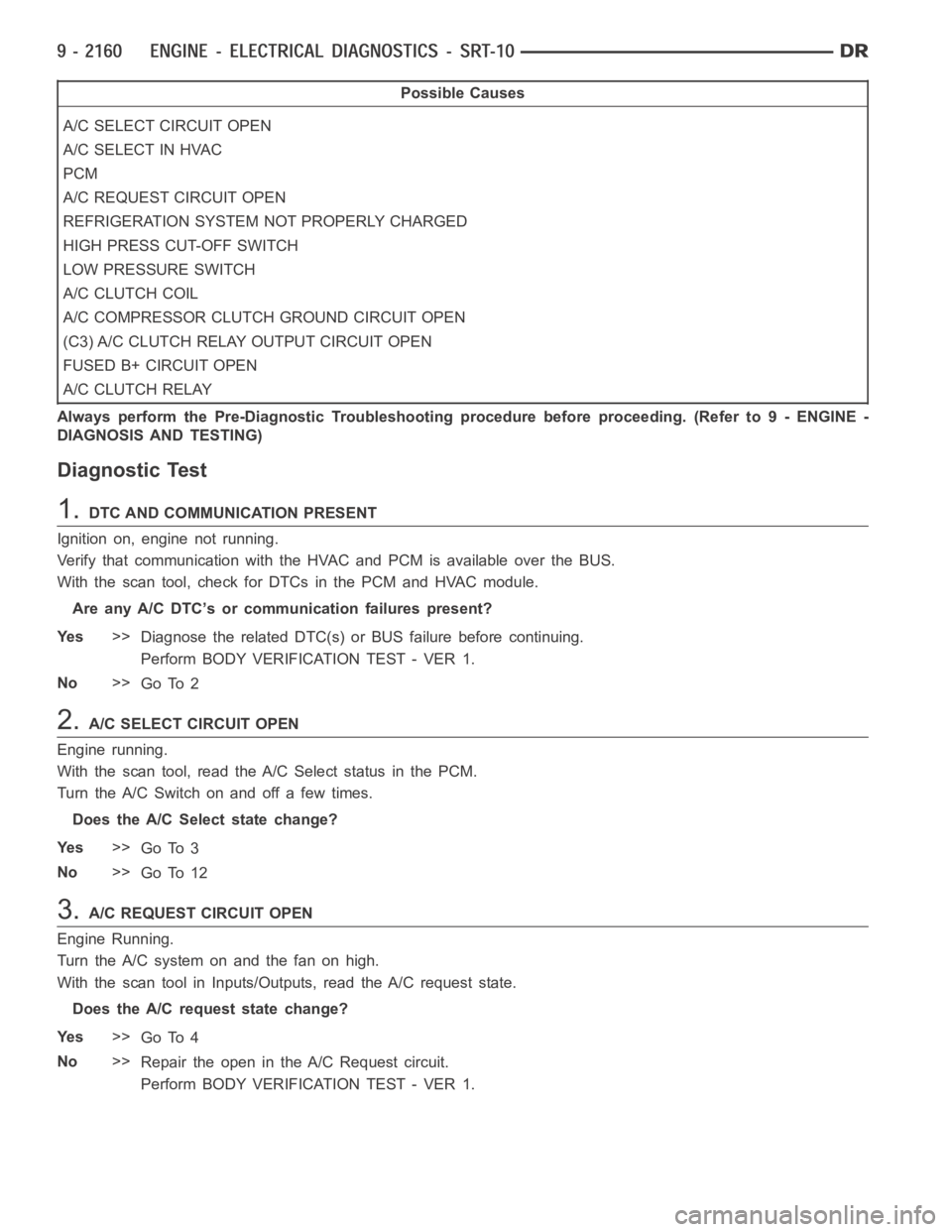
Possible Causes
A/C SELECT CIRCUIT OPEN
A/C SELECT IN HVAC
PCM
A/C REQUEST CIRCUIT OPEN
REFRIGERATION SYSTEM NOT PROPERLY CHARGED
HIGH PRESS CUT-OFF SWITCH
LOW PRESSURE SWITCH
A/CCLUTCHCOIL
A/C COMPRESSOR CLUTCH GROUND CIRCUIT OPEN
(C3) A/C CLUTCH RELAY OUTPUT CIRCUIT OPEN
FUSED B+ CIRCUIT OPEN
A/CCLUTCHRELAY
Always perform the Pre-Diagnostic Troubleshooting procedure before proceeding. (Refer to 9 - ENGINE -
DIAGNOSIS AND TESTING)
Diagnostic Test
1.DTC AND COMMUNICATION PRESENT
Ignition on, engine not running.
Verify that communication with the HVAC and PCM is available over the BUS.
With the scan tool, check for DTCs in the PCM and HVAC module.
Are any A/C DTC’s or communication failures present?
Ye s>>
Diagnose the related DTC(s) or BUS failure before continuing.
Perform BODY VERIFICATION TEST - VER 1.
No>>
Go To 2
2.A/C SELECT CIRCUIT OPEN
Engine running.
With the scan tool, read the A/C Select status in the PCM.
Turn the A/C Switch on and off a few times.
Does the A/C Select state change?
Ye s>>
Go To 3
No>>
Go To 12
3.A/C REQUEST CIRCUIT OPEN
Engine Running.
Turn the A/C system on and the fan on high.
With the scan tool in Inputs/Outputs, read the A/C request state.
Does the A/C request state change?
Ye s>>
Go To 4
No>>
Repair the open in the A/C Request circuit.
Perform BODY VERIFICATION TEST - VER 1.
Page 1470 of 5267
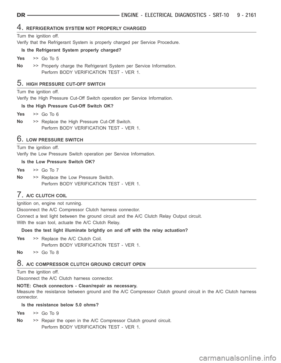
4.REFRIGERATION SYSTEM NOT PROPERLY CHARGED
Turn the ignition off.
Verify that the Refrigerant System is properly charged per Service Procedure.
Is the Refrigerant System properly charged?
Ye s>>
Go To 5
No>>
Properly charge the Refrigerant System per Service Information.
Perform BODY VERIFICATION TEST - VER 1.
5.HIGH PRESSURE CUT-OFF SWITCH
Turn the ignition off.
Verify the High Pressure Cut-Off Switch operation per Service Information.
Is the High Pressure Cut-Off Switch OK?
Ye s>>
Go To 6
No>>
Replace the High Pressure Cut-Off Switch.
Perform BODY VERIFICATION TEST - VER 1.
6.LOW PRESSURE SWITCH
Turn the ignition off.
Verify the Low Pressure Switch operation per Service Information.
Is the Low Pressure Switch OK?
Ye s>>
Go To 7
No>>
Replace the Low Pressure Switch.
Perform BODY VERIFICATION TEST - VER 1.
7.A/C CLUTCH COIL
Ignition on, engine not running.
Disconnect the A/C Compressor Clutch harness connector.
Connect a test light between the ground circuit and the A/C Clutch Relay Output circuit.
With the scan tool, actuate the A/C Clutch Relay.
Does the test light illuminate brightly on and off with the relay actuation?
Ye s>>
Replace the A/C Clutch Coil.
Perform BODY VERIFICATION TEST - VER 1.
No>>
Go To 8
8.A/C COMPRESSOR CLUTCH GROUND CIRCUIT OPEN
Turn the ignition off.
Disconnect the A/C Clutch harness connector.
NOTE: Check connectors - Clean/repair as necessary.
Measure the resistance between ground and the A/C Compressor Clutch ground circuit in the A/C Clutch harness
connector.
Is the resistance below 5.0 ohms?
Ye s>>
Go To 9
No>>
Repair the open in the A/C Compressor Clutch ground circuit.
Perform BODY VERIFICATION TEST - VER 1.
Page 1471 of 5267
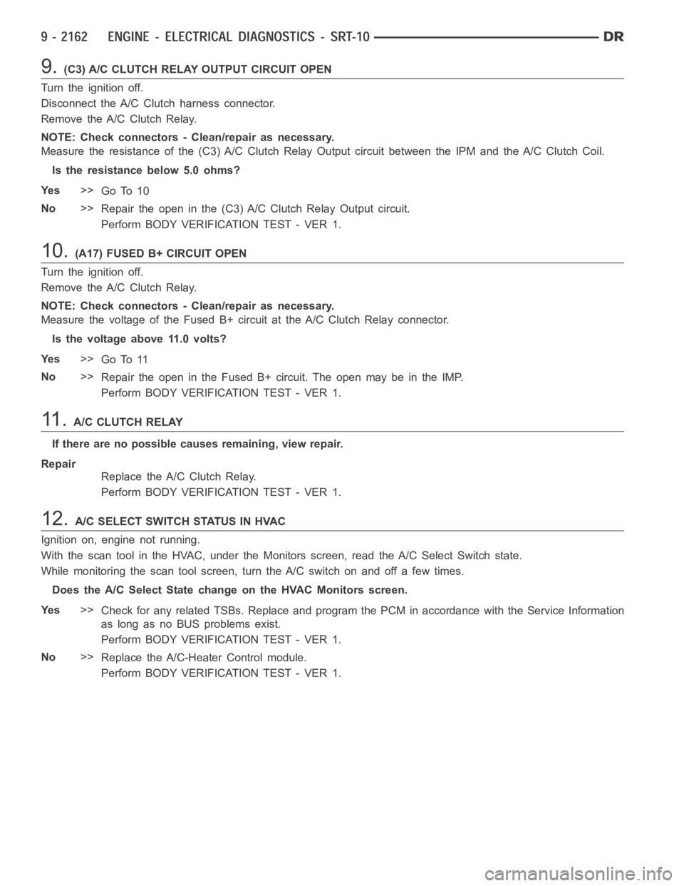
9.(C3) A/C CLUTCH RELAY OUTPUT CIRCUIT OPEN
Turn the ignition off.
Disconnect the A/C Clutch harness connector.
Remove the A/C Clutch Relay.
NOTE: Check connectors - Clean/repair as necessary.
Measure the resistance of the (C3) A/C Clutch Relay Output circuit betweenthe IPM and the A/C Clutch Coil.
Is the resistance below 5.0 ohms?
Ye s>>
Go To 10
No>>
Repair the open in the (C3) A/C Clutch Relay Output circuit.
Perform BODY VERIFICATION TEST - VER 1.
10.(A17) FUSED B+ CIRCUIT OPEN
Turn the ignition off.
Remove the A/C Clutch Relay.
NOTE: Check connectors - Clean/repair as necessary.
Measure the voltage of the Fused B+ circuit at the A/C Clutch Relay connector.
Is the voltage above 11.0 volts?
Ye s>>
Go To 11
No>>
Repair the open in the Fused B+ circuit. The open may be in the IMP.
Perform BODY VERIFICATION TEST - VER 1.
11 .A/C CLUTCH RELAY
If there are no possible causes remaining, view repair.
Repair
Replace the A/C Clutch Relay.
Perform BODY VERIFICATION TEST - VER 1.
12.A/CSELECTSWITCHSTATUSINHVAC
Ignition on, engine not running.
With the scan tool in the HVAC, under the Monitors screen, read the A/C Select Switch state.
While monitoring the scan tool screen, turn the A/C switch on and off a few times.
Does the A/C Select State change on the HVAC Monitors screen.
Ye s>>
Check for any related TSBs. Replace and program the PCM in accordance with the Service Information
as long as no BUS problems exist.
Perform BODY VERIFICATION TEST - VER 1.
No>>
Replace the A/C-Heater Control module.
Perform BODY VERIFICATION TEST - VER 1.
Page 1475 of 5267
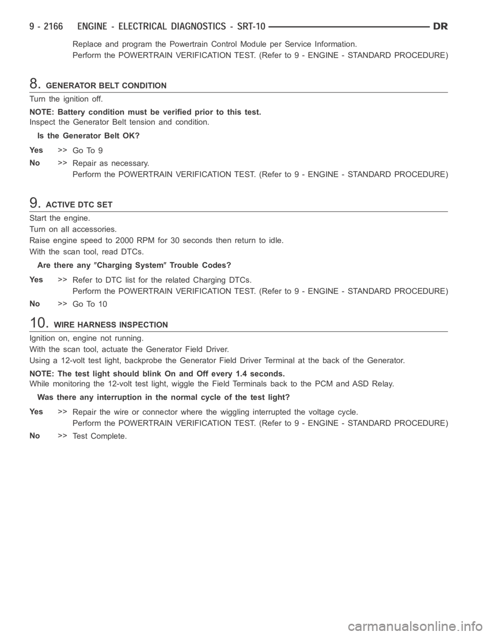
Replace and program the Powertrain Control Module per Service Information.
Perform the POWERTRAIN VERIFICATION TEST. (Refer to 9 - ENGINE - STANDARD PROCEDURE)
8.GENERATOR BELT CONDITION
Turn the ignition off.
NOTE: Battery condition must be verified prior to this test.
Inspect the Generator Belt tension and condition.
Is the Generator Belt OK?
Ye s>>
Go To 9
No>>
Repair as necessary.
Perform the POWERTRAIN VERIFICATION TEST. (Refer to 9 - ENGINE - STANDARD PROCEDURE)
9.ACTIVE DTC SET
Start the engine.
Turn on all accessories.
Raise engine speed to 2000 RPM for 30 seconds then return to idle.
With the scan tool, read DTCs.
Are there any
Charging SystemTrouble Codes?
Ye s>>
Refer to DTC list for the related Charging DTCs.
Perform the POWERTRAIN VERIFICATION TEST. (Refer to 9 - ENGINE - STANDARD PROCEDURE)
No>>
Go To 10
10.WIRE HARNESS INSPECTION
Ignition on, engine not running.
With the scan tool, actuate the Generator Field Driver.
Using a 12-volt test light, backprobe the Generator Field Driver Terminalat the back of the Generator.
NOTE: The test light should blink On and Off every 1.4 seconds.
While monitoring the 12-volt test light, wiggle the Field Terminals back to the PCM and ASD Relay.
Was there any interruption in the normal cycle of the test light?
Ye s>>
Repair the wire or connector where the wiggling interrupted the voltage cycle.
Perform the POWERTRAIN VERIFICATION TEST. (Refer to 9 - ENGINE - STANDARD PROCEDURE)
No>>
Te s t C o m p l e t e .
Page 1477 of 5267
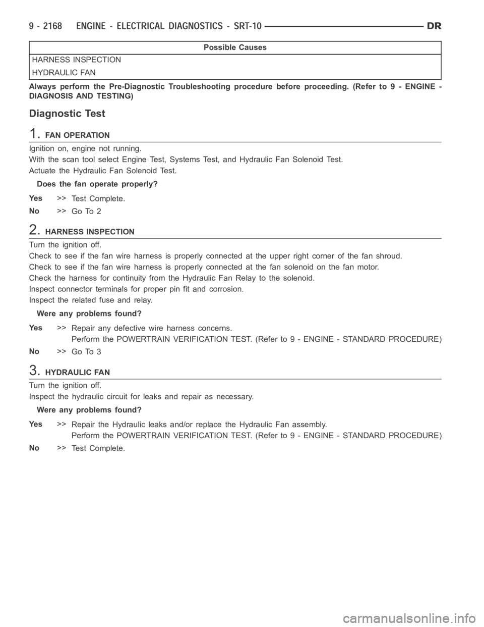
Possible Causes
HARNESS INSPECTION
HYDRAULIC FAN
Always perform the Pre-Diagnostic Troubleshooting procedure before proceeding. (Refer to 9 - ENGINE -
DIAGNOSIS AND TESTING)
Diagnostic Test
1.FAN OPERATION
Ignition on, engine not running.
With the scan tool select Engine Test, Systems Test, and Hydraulic Fan Solenoid Test.
Actuate the Hydraulic Fan Solenoid Test.
Does the fan operate properly?
Ye s>>
Te s t C o m p l e t e .
No>>
Go To 2
2.HARNESS INSPECTION
Turn the ignition off.
Check to see if the fan wire harness is properly connected at the upper rightcorner of the fan shroud.
Check to see if the fan wire harness is properly connected at the fan solenoidonthefanmotor.
Check the harness for continuity from the Hydraulic Fan Relay to the solenoid.
Inspect connector terminals for proper pin fit and corrosion.
Inspect the related fuse and relay.
Were any problems found?
Ye s>>
Repair any defective wire harness concerns.
Perform the POWERTRAIN VERIFICATION TEST. (Refer to 9 - ENGINE - STANDARD PROCEDURE)
No>>
Go To 3
3.HYDRAULIC FAN
Turn the ignition off.
Inspect the hydraulic circuit for leaks and repair as necessary.
Were any problems found?
Ye s>>
Repair the Hydraulic leaks and/or replace the Hydraulic Fan assembly.
Perform the POWERTRAIN VERIFICATION TEST. (Refer to 9 - ENGINE - STANDARD PROCEDURE)
No>>
Te s t C o m p l e t e .
Page 1490 of 5267
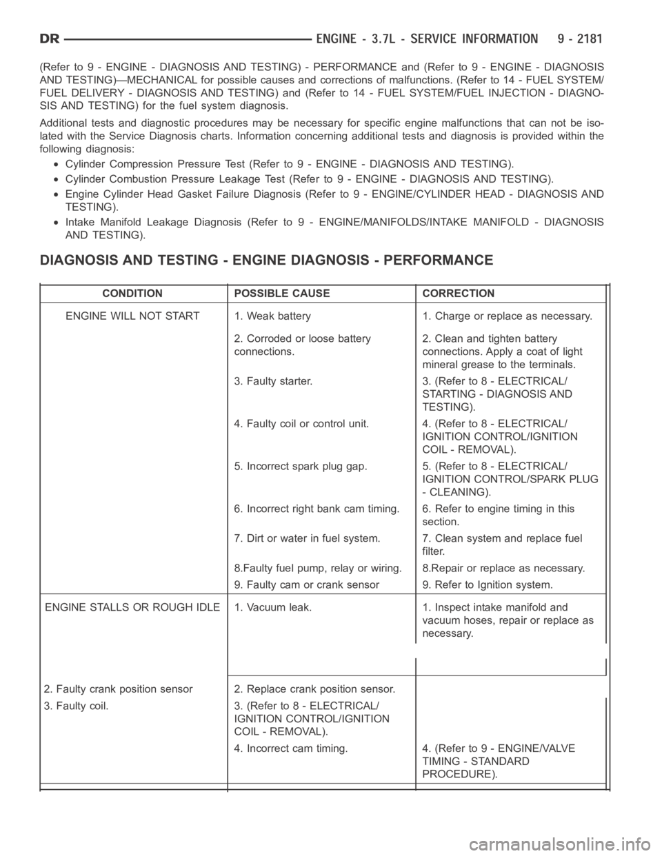
(Refer to 9 - ENGINE - DIAGNOSIS AND TESTING) - PERFORMANCE and (Refer to 9 - ENGINE - DIAGNOSIS
AND TESTING)—MECHANICAL for possible causes and corrections of malfunctions. (Refer to 14 - FUEL SYSTEM/
FUEL DELIVERY - DIAGNOSIS AND TESTING) and (Refer to 14 - FUEL SYSTEM/FUEL INJECTION - DIAGNO-
SIS AND TESTING) for the fuel system diagnosis.
Additional tests and diagnostic procedures may be necessary for specificengine malfunctions that can not be iso-
lated with the Service Diagnosis charts. Information concerning additional tests and diagnosis is provided within the
following diagnosis:
Cylinder Compression Pressure Test (Refer to 9 - ENGINE - DIAGNOSIS AND TESTING).
Cylinder Combustion Pressure LeakageTest (Refer to 9 - ENGINE - DIAGNOSISAND TESTING).
Engine Cylinder Head Gasket Failure Diagnosis (Refer to 9 - ENGINE/CYLINDER HEAD - DIAGNOSIS AND
TESTING).
Intake Manifold Leakage Diagnosis (Refer to 9 - ENGINE/MANIFOLDS/INTAKEMANIFOLD - DIAGNOSIS
AND TESTING).
DIAGNOSIS AND TESTING - ENGINE DIAGNOSIS - PERFORMANCE
CONDITION POSSIBLE CAUSE CORRECTION
ENGINE WILL NOT START 1. Weak battery 1. Charge or replace as necessary.
2. Corroded or loose battery
connections.2. Clean and tighten battery
connections. Apply a coat of light
mineral grease to the terminals.
3. Faulty starter. 3. (Refer to 8 - ELECTRICAL/
STARTING - DIAGNOSIS AND
TESTING).
4. Faulty coil or control unit. 4. (Refer to 8 - ELECTRICAL/
IGNITION CONTROL/IGNITION
COIL - REMOVAL).
5. Incorrect spark plug gap. 5. (Refer to 8 - ELECTRICAL/
IGNITION CONTROL/SPARK PLUG
- CLEANING).
6. Incorrect right bank cam timing. 6. Refer to engine timing in this
section.
7. Dirt or water in fuel system. 7. Clean system and replace fuel
filter.
8.Faulty fuel pump, relay or wiring. 8.Repair or replace as necessary.
9. Faulty cam or crank sensor 9. Refer to Ignition system.
ENGINE STALLS OR ROUGH IDLE 1. Vacuum leak. 1. Inspect intake manifold and
vacuum hoses, repair or replace as
necessary.
2. Faulty crank position sensor 2. Replace crank position sensor.
3. Faulty coil. 3. (Refer to 8 - ELECTRICAL/
IGNITION CONTROL/IGNITION
COIL - REMOVAL).
4. Incorrect cam timing. 4. (Refer to 9 - ENGINE/VALVE
TIMING - STANDARD
PROCEDURE).
Page 1494 of 5267
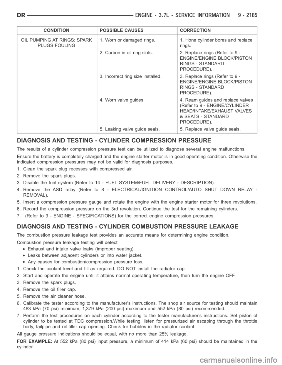
CONDITION POSSIBLE CAUSES CORRECTION
OIL PUMPING AT RINGS; SPARK
PLUGS FOULING1. Worn or damaged rings. 1. Hone cylinder bores and replace
rings.
2. Carbon in oil ring slots. 2. Replace rings (Refer to 9 -
ENGINE/ENGINE BLOCK/PISTON
RINGS - STANDARD
PROCEDURE).
3. Incorrect ring size installed. 3. Replace rings (Refer to 9 -
ENGINE/ENGINE BLOCK/PISTON
RINGS - STANDARD
PROCEDURE).
4. Worn valve guides. 4. Ream guides and replace valves
(Refer to 9 - ENGINE/CYLINDER
HEAD/INTAKE/EXHAUST VALVES
& SEATS - STANDARD
PROCEDURE).
5. Leaking valve guide seals. 5. Replace valve guide seals.
DIAGNOSIS AND TESTING - CYLINDER COMPRESSION PRESSURE
The results of a cylinder compressionpressure test can be utilized to diagnose several engine malfunctions.
Ensurethebatteryiscompletelychargedandtheenginestartermotorisingood operating condition. Otherwise the
indicated compression pressures may not be valid for diagnosis purposes.
1. Clean the spark plug recesses with compressed air.
2. Remove the spark plugs.
3. Disable the fuel system (Refer to 14 - FUEL SYSTEM/FUEL DELIVERY - DESCRIPTION).
4. Remove the ASD relay (Refer to 8 - ELECTRICAL/IGNITION CONTROL/AUTO SHUTDOWNRELAY-
REMOVAL).
5. Insert a compression pressure gauge and rotate the engine with the engine starter motor for three revolutions.
6. Record the compression pressure on the 3rd revolution. Continue the test for the remaining cylinders.
7. (Refer to 9 - ENGINE - SPECIFICATIONS) for the correct engine compression pressures.
DIAGNOSIS AND TESTING - CYLINDERCOMBUSTION PRESSURE LEAKAGE
The combustion pressure leakage test provides an accurate means for determining engine condition.
Combustion pressure leakage testing will detect:
Exhaust and intake valve leaks (improper seating).
Leaks between adjacent cylinders or into water jacket.
Any causes for combustion/compression pressure loss.
1. Check the coolant level and fill as required. DO NOT install the radiatorcap.
2. Start and operate the engine until it attains normal operating temperature, then turn the engine OFF.
3. Remove the spark plugs.
4. Remove the oil filler cap.
5. Remove the air cleaner hose.
6. Calibrate the tester according to the manufacturer’s instructions. The shop air source for testing should maintain
483 kPa (70 psi) minimum, 1,379 kPa (200 psi) maximum and 552 kPa (80 psi) recommended.
7. Perform the test procedures on each cylinder according to the tester manufacturer’s instructions. Set piston of
cylinder to be tested at TDC compression,While testing, listen for pressurized air escaping through the throttle
body, tailpipe and oil filler cap opening. Check for bubbles in the radiator coolant.
All gauge pressure indications should be equal, with no more than 25% leakage.
FOR EXAMPLE:At 552 kPa (80 psi) input pressure, a minimum of 414 kPa (60 psi) should be maintained in the
cylinder.
Page 1625 of 5267
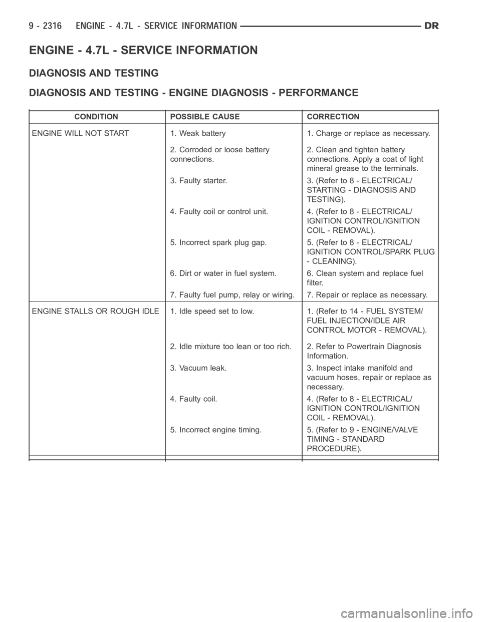
ENGINE - 4.7L - SERVICE INFORMATION
DIAGNOSIS AND TESTING
DIAGNOSIS AND TESTING - ENGINE DIAGNOSIS - PERFORMANCE
CONDITION POSSIBLE CAUSE CORRECTION
ENGINE WILL NOT START 1. Weak battery 1. Charge or replace as necessary.
2. Corroded or loose battery
connections.2. Clean and tighten battery
connections. Apply a coat of light
mineral grease to the terminals.
3. Faulty starter. 3. (Refer to 8 - ELECTRICAL/
STARTING - DIAGNOSIS AND
TESTING).
4. Faulty coil or control unit. 4. (Refer to 8 - ELECTRICAL/
IGNITION CONTROL/IGNITION
COIL - REMOVAL).
5. Incorrect spark plug gap. 5. (Refer to 8 - ELECTRICAL/
IGNITION CONTROL/SPARK PLUG
- CLEANING).
6. Dirt or water in fuel system. 6. Clean system and replace fuel
filter.
7. Faulty fuel pump, relay or wiring. 7. Repair or replace as necessary.
ENGINE STALLS OR ROUGH IDLE 1. Idle speed set to low. 1. (Refer to 14 - FUEL SYSTEM/
FUEL INJECTION/IDLE AIR
CONTROL MOTOR - REMOVAL).
2. Idle mixture too lean or too rich. 2. Refer to Powertrain Diagnosis
Information.
3. Vacuum leak. 3. Inspect intake manifold and
vacuum hoses, repair or replace as
necessary.
4. Faulty coil. 4. (Refer to 8 - ELECTRICAL/
IGNITION CONTROL/IGNITION
COIL - REMOVAL).
5. Incorrect engine timing. 5. (Refer to 9 - ENGINE/VALVE
TIMING - STANDARD
PROCEDURE).
Page 1628 of 5267
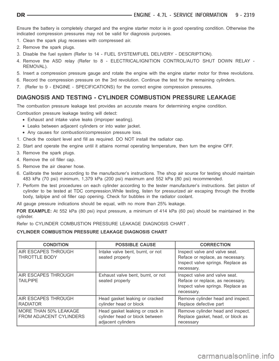
Ensurethebatteryiscompletelychargedandtheenginestartermotorisingood operating condition. Otherwise the
indicated compression pressures may not be valid for diagnosis purposes.
1. Clean the spark plug recesses with compressed air.
2. Remove the spark plugs.
3. Disable the fuel system (Refer to 14 - FUEL SYSTEM/FUEL DELIVERY - DESCRIPTION).
4. Remove the ASD relay (Refer to 8 - ELECTRICAL/IGNITION CONTROL/AUTO SHUTDOWNRELAY-
REMOVAL).
5. Insert a compression pressure gauge and rotate the engine with the engine starter motor for three revolutions.
6. Record the compression pressure on the 3rd revolution. Continue the test for the remaining cylinders.
7. (Refer to 9 - ENGINE - SPECIFICATIONS) for the correct engine compression pressures.
DIAGNOSIS AND TESTING - CYLINDERCOMBUSTION PRESSURE LEAKAGE
The combustion pressure leakage test provides an accurate means for determining engine condition.
Combustion pressure leakage testing will detect:
Exhaust and intake valve leaks (improper seating).
Leaks between adjacent cylinders or into water jacket.
Any causes for combustion/compression pressure loss.
1. Check the coolant level and fill as required. DO NOT install the radiatorcap.
2. Start and operate the engine until it attains normal operating temperature, then turn the engine OFF.
3. Remove the spark plugs.
4. Remove the oil filler cap.
5. Remove the air cleaner hose.
6. Calibrate the tester according to the manufacturer’s instructions. The shop air source for testing should maintain
483 kPa (70 psi) minimum, 1,379 kPa (200 psi) maximum and 552 kPa (80 psi) recommended.
7. Perform the test procedures on each cylinder according to the tester manufacturer’s instructions. Set piston of
cylinder to be tested at TDC compression,While testing, listen for pressurized air escaping through the throttle
body, tailpipe and oil filler cap opening. Check for bubbles in the radiator coolant.
All gauge pressure indications should be equal, with no more than 25% leakage.
FOR EXAMPLE:At 552 kPa (80 psi) input pressure, a minimum of 414 kPa (60 psi) should be maintained in the
cylinder.
Refer to CYLINDER COMBUSTION PRESSURE LEAKAGE DIAGNOSIS CHART .
CYLINDER COMBUSTION PRESSURE LEAKAGE DIAGNOSIS CHART
CONDITION POSSIBLE CAUSE CORRECTION
AIR ESCAPES THROUGH
THROTTLE BODYIntake valve bent, burnt, or not
seated properlyInspect valve and valve seat.
Reface or replace, as necessary.
Inspect valve springs. Replace as
necessary.
AIR ESCAPES THROUGH
TAILPIPEExhaust valve bent, burnt, or not
seated properlyInspect valve and valve seat.
Reface or replace, as necessary.
Inspect valve springs. Replace as
necessary.
AIR ESCAPES THROUGH
RADIATORHead gasket leaking or cracked
cylinder head or blockRemove cylinder head and inspect.
Replace defective part
MORE THAN 50% LEAKAGE
FROM ADJACENT CYLINDERSHead gasket leaking or crack in
cylinder head or block between
adjacent cylindersRemove cylinder head and inspect.
Replace gasket, head, or block as
necessary