relay DODGE RAM SRT-10 2006 Service Repair Manual
[x] Cancel search | Manufacturer: DODGE, Model Year: 2006, Model line: RAM SRT-10, Model: DODGE RAM SRT-10 2006Pages: 5267, PDF Size: 68.7 MB
Page 2887 of 5267
3.PCM AND WIRING
Turn the ignition off to the lock position.
Remove the Ignition Switch Feed fuse from the TIPM.
CAUTION: Removal of the Ignition Switch Feed fuse from the TIPM will prevent the vehicle from being
startedingear.
WARNING: The Ignition Switch Feed fuse must be removed from the TIPM. Failure to do so can result in
personal injury or death.
Install the Transmission Simulator,Miller tool #8333 and the ElectronicTransmission Adapter kit.
Ignition on, engine not running.
With the Transmission Simulator, turn the Pressure Switch selector switchtoL/R.
With the scan tool, monitor the L/R Pressure Switch State while pressing the Pressure Switch Test button.
Did the Pressure Switch state change from open to closed when the test button was pressed?
Ye s>>
Repair internal transmission as necessary per the Service Information. Inspect the Solenoid Switch
Valve per the Service Information and repair or replace as necessary. If noproblems are found, replace
the Transmission Solenoid/Pressure Switch Assembly.
Perform 42RLE TRANSMISSION VERIFICATION TEST - VER 1. (Refer to 21 - TRANSMISSION/
TRANSAXLE/AUTOMATIC - 42RLE - STANDARD PROCEDURE)
No>>
Go To 4
4.(T16) TRANSMISSION CONTROL OUTPUT CIRCUIT OPEN
Turn the ignition off to the lock position.
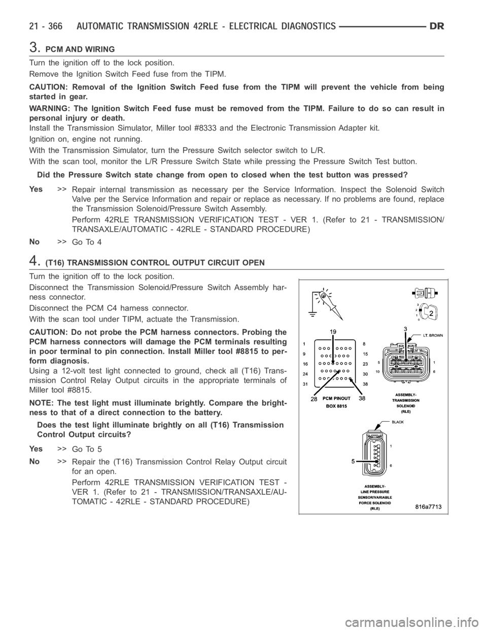
Disconnect the Transmission Solenoid/Pressure Switch Assembly har-
ness connector.
Disconnect the PCM C4 harness connector.
With the scan tool under TIPM, actuate the Transmission.
CAUTION: Do not probe the PCM harness connectors. Probing the
PCM harness connectors will damage the PCM terminals resulting
in poor terminal to pin connection. Install Miller tool #8815 to per-
form diagnosis.
Using a 12-volt test light connected to ground, check all (T16) Trans-
mission Control Relay Output circuits in the appropriate terminals of
Miller tool #8815.
NOTE: The test light must illuminate brightly. Compare the bright-
ness to that of a direct connection to the battery.
Does the test light illuminate brightly on all (T16) Transmission
Control Output circuits?
Ye s>>
Go To 5
No>>
Repair the (T16) Transmission Control Relay Output circuit
for an open.
Perform 42RLE TRANSMISSION VERIFICATION TEST -
VER 1. (Refer to 21 - TRANSMISSION/TRANSAXLE/AU-
TOMATIC - 42RLE - STANDARD PROCEDURE)
Page 2911 of 5267
MECHANISM-SHIFT
DESCRIPTION ............................... 536
OPERATION ................................. 536
SOLENOID
DESCRIPTION ............................... 537
OPERATION ................................. 538
ASSEMBLY-TRANSMISSION SOLENOID/
PRESSURE SWITCH
DESCRIPTION ............................... 539
OPERATION ................................. 539
REMOVAL ................................... 540
INSTALLATION .............................. 541
CONVERTER-TORQUE
DESCRIPTION ............................... 542
OPERATION ................................. 546
REMOVAL ................................... 548
INSTALLATION .............................. 549
SWITCH-TOW/HAUL OVERDRIVE
DESCRIPTION ............................... 550
OPERATION ................................. 550REMOVAL ................................... 550
INSTALLATION .............................. 551
RELAY-TRANSMISSION CONTROL
DESCRIPTION ............................... 552
OPERATION ................................. 552
SENSOR-TRANSMISSION RANGE
DESCRIPTION ............................... 553
OPERATION ................................. 553
REMOVAL ................................... 554
INSTALLATION .............................. 555
SENSOR-TRANSMISSION TEMPERATURE
DESCRIPTION ............................... 556
OPERATION ................................. 556
BODY-VALVE
DESCRIPTION ............................... 557
OPERATION ................................. 558
REMOVAL ................................... 562
DISASSEMBLY .............................. 564
ASSEMBLY .................................. 571
INSTALLATION .............................. 578
Page 2914 of 5267
The 42RLE is a four-speed transmission that is a conventional hydraulic/mechanical assembly controlled with adap-
tive electronic controls and monitors. The hydraulic system of the transmission consists of the transmission fluid,
fluid passages, hydraulic valves, and various line pressure control components. An input clutch assembly which
houses the underdrive, overdrive, and reverse clutches is used. It also utilizes separate holding clutches: 2nd/4th
gear and Low/Reverse. The primary mechanical components of the transmission consist of the following:
Three multiple disc input clutches
Two multiple disc holding clutches
Four hydraulic accumulators
Two planetary gear sets
Hydraulic oil pump
Valve body
Solenoid/Pressure switch assembly
Control of the transmission is accomplished by fully adaptive electronics. Optimum shift scheduling is accomplished
through continuous real-time sensor feedback information provided to the Transmission Control Module (TCM) por-
tion of the Powertrain Control Module (PCM).
The TCM is the heart of the electronic control system and relies on information from various direct and indirect
inputs (sensors, switches, etc.) to determine driver demand and vehicle operating conditions. With this information,
the TCM can calculate and perform timely and quality shifts through various output or control devices (solenoid
pack, transmission control relay, etc.).
The TCM also performs certain self-diagnostic functions and provides comprehensive information (sensor data,
DTC’s, etc.) which is helpful in proper diagnosis and repair. This informationcanbeviewedwiththescantool.
TRANSMISSION IDENTIFICATION
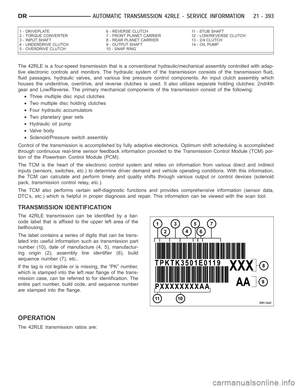
The 42RLE transmission can be identified by a bar-
code label that is affixed to the upper left area of the
bellhousing.
The label contains a series of digits that can be trans-
lated into useful information such as transmission part
number (10), date of manufacture (4, 5), manufactur-
ing origin (2), assembly line identifier (6), build
sequence number (7), etc..
If the tag is not legible or is missing, the “PK” number,
which is stamped into the left rear flange of the trans-
mission case, can be referred to for identification. The
entire part number, build code, and sequence number
are stamped into the flange.
OPERATION
The 42RLE transmission ratios are:
1 - DRIVEPLATE 6 - REVERSE CLUTCH 11 - STUB SHAFT
2 - TORQUE CONVERTER 7 - FRONT PLANET CARRIER 12 - LOW/REVERSE CLUTCH
3 - INPUT SHAFT 8 - REAR PLANET CARRIER 13 - 2/4 CLUTCH
4 - UNDERDRIVE CLUTCH 9 - OUTPUT SHAFT 14 - OIL PUMP
5 - OVERDRIVE CLUTCH 10 - SNAP RING
Page 3060 of 5267
ASSEMBLY-TRANSMISSION SOLENOID/PRESSURE SWITCH
DESCRIPTION
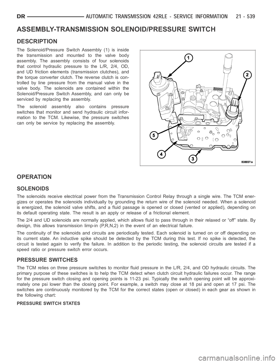
The Solenoid/Pressure Switch Assembly (1) is inside
the transmission and mounted to the valve body
assembly. The assembly consists of four solenoids
that control hydraulic pressure to the L/R, 2/4, OD,
and UD friction elements (transmission clutches), and
the torque converter clutch. The reverse clutch is con-
trolled by line pressure from the manual valve in the
valve body. The solenoids are contained within the
Solenoid/Pressure Switch Assembly, and can only be
serviced by replacing the assembly.
The solenoid assembly also contains pressure
switches that monitor and send hydraulic circuit infor-
mation to the TCM. Likewise, the pressure switches
can only be service by replacing the assembly.
OPERATION
SOLENOIDS
The solenoids receive electrical power from the Transmission Control Relay through a single wire. The TCM ener-
gizes or operates the solenoids individually by grounding the return wireof the solenoid needed. When a solenoid
is energized, the solenoid valve shifts, and a fluid passage is opened or closed (vented or applied), depending on
its default operating state. The result is an apply or release of a frictional element.
The 2/4 and UD solenoids are normally applied, which allows fluid to pass throughintheirrelaxedor“off”state.By
design, this allows transmission limp-in (P,R,N,2) in the event of an electrical failure.
The continuity of the solenoids and circuits are periodically tested. Each solenoid is turned on or off depending on
its current state. An inductive spike should be detected by the TCM during this test. If no spike is detected, the
circuit is tested again to verify the failure. In addition to the periodic testing, the solenoid circuits are tested if a
speed ratio or pressure switch error occurs.
PRESSURE SWITCHES
The TCM relies on three pressure switches to monitor fluid pressure in the L/R, 2/4, and OD hydraulic circuits. The
primary purpose of these switches is to help the TCM detect when clutch circuit hydraulic failures occur. The range
for the pressure switch closing and opening points is 11-23 psi. Typicallythe switch opening point will be approxi-
mately one psi lower than the closing point. For example, a switch may closeat 18 psi and open at 17 psi. The
switches are continuously monitored by the TCM for the correct states (open or closed) in each gear as shown in
the following chart:
PRESSURE SWITCH STATES
Page 3073 of 5267
RELAY-TRANSMISSION CONTROL
DESCRIPTION
The relay is supplied fused B+ voltage, energized by the TCM, and is used to supply power to the solenoid pack
when the transmission is in normal operating mode.
OPERATION
When the relay is “off”, no power is supplied to the solenoid pack and the transmission is in “limp-in” mode. After a
controller reset, the TCM energizes the relay. Prior to this, the TCM verifies that the contacts are open by checking
for no voltage at the switched batteryterminals. After this is verified, the voltage at the solenoid pack pressure
switches is checked. After the relay is energized, the TCM monitors the terminals to verify that the voltage is greater
than 3 volts.
Page 3111 of 5267
When Monitored:
With the engine running and the PCM has closed the Transmission Control Relay.
Set Condition:
If the battery voltage of the Transmission Output circuit(s) to the PCM is less than 10.0 volts for the period of
15 seconds. Note: P0562 generally indicates a gradually falling battery voltage or a resistive connection(s) to
the PCM. The DTC will also set if the battery voltage sensed at the PCM is lessthan 6.5-volts for 200ms or
where the Transmission Output circuits are less than 7.2-volts for 200ms.
Possible Causes
RELATED CHARGING SYSTEM DTC’S
(Z904, Z908, Z977) GROUND CIRCUITS OPEN OR HIGH RESISTANCE
(T16) TIPM OUTPUT CIRCUIT OPEN OR HIGH RESISTANCE
TOTALLY INTEGRATED POWER MODULE (TIPM)
POWERTRAIN CONTROL MODULE
Always perform the 45RFE/545RFE Pre-Diagnostic Troubleshooting Procedure before proceeding. (Refer to
21 - TRANSMISSION/TRANSAXLE/AUTOMATIC - 45RFE/545RFE - STANDARD PROCEDURE)
Theory of Operation
Friction element distress could result from an insufficient supply voltage to properly control the solenoids. To prevent
this possibility, the battery voltage is monitored and the system is placed in logical limp-in if the battery voltage
drops below the limit.
Diagnostic Test
1.RELATED CHARGING SYSTEM DTCS
With the scan tool, read the Engine DTCs.
Are there any related Charging System DTCs also present?
Ye s>>
Refer to the Charging System category and repair any Engine Charging System DTCs, before testing
DTC P0562. NOTE: After repairing the Engine Charging System DTC’s, perform the Transmission Ver-
ification test to verify the transmission control systemwas not damaged.
Perform 45RFE/545RFE TRANSMISSION VERIFICATION TEST - VER 1. (Refer to 21- TRANSMIS-
SION/TRANSAXLE/AUTOMATIC - 45RFE/545RFE - STANDARD PROCEDURE)
No>>
Go To 2
2.CHECK FOR TIPM DTCS
NOTE: Generator, battery, and charging system must be fully functional before performing this test.
With the scan tool, read TIPM DTCs.
Are there any TCM TIPM DTCs present.
Ye s>>
Refer to the Transmission category and perform the appropriate symptom. (Refer to 21 - TRANSMIS-
SION/TRANSAXLE/AUTOMATIC - 45RFE/545RFE - DIAGNOSIS AND TESTING)
No>>
Go To 3
Page 3116 of 5267
P0604-INTERNAL CONTROL MODULE RAM
For a complete wiring diagramRefer to Section 8W.
Theory of Operation
After the controller is reset (ignition turned to the RUN position), the microprocessor checks the integrity of each
RAM location by writing to it and reading back from it. The read value shouldbe same as value written.
When Monitored:
One time after the controller is reset (ignition turned to the RUN position).
Set Condition:
Whenever the Powertrain Control Module (PCM) detects an internal controller problem.
Possible Causes
POWERORGROUNDCIRCUIT
POWERTRAIN CONTROL MODULE
Always perform the Pre-Diagnostic Troubleshooting procedure before proceeding. (Refer to 21 - TRANSMIS-
SION/TRANSAXLE/AUTOMATIC - 45RFE/545RFE - STANDARD PROCEDURE)
Diagnostic Test
1.CHECK WIRING AND CONNECTORS FOR INTERMITTENT OPERATION
Using the schematics as a guide, check the Powertrain Control Module (PCM)terminals for corrosion, damage, or
terminal push out. Pay particular attention to all power and ground circuits.
NOTE: Due to the integration of the Powertrain and Transmission Control Modules, the transmission part of
the PCM has it’s own specific power and ground circuits.
Wiggle the wires while checking for shorted and open circuits.
Check for any Service Bulletins that may apply.
Were there any problems found?
Ye s>>
Repair the power and/or ground circuits to the PCM and Transmission Control Relay as necessary.
Perform 45RFE/545RFE TRANSMISSION VERIFICATION TEST - VER 1. (Refer to 21- TRANSMIS-
SION/TRANSAXLE/AUTOMATIC - 45RFE/545RFE - STANDARD PROCEDURE)
No>>
Replace the PCM per the Service Information. With the scan tool, perform QUICK LEARN.
Perform 45RFE/545RFE TRANSMISSION VERIFICATION TEST - VER 1. (Refer to 21- TRANSMIS-
SION/TRANSAXLE/AUTOMATIC - 45RFE/545RFE - STANDARD PROCEDURE)
Page 3118 of 5267
P0613-INTERNAL TCM
For a complete wiring diagramRefer to Section 8W.
Theory of Operation
The internal Watchdog (WD) is a separate hardware circuit that continuously monitors the microprocessor. To insure
the proper operation of the Transmission controller the watchdog must receive a signal from the microprocessor
within a specific time window (14 msec ± 1 msec) to prevent a system shutdownafter a short delay (570 msec).
The microprocessor periodically tests the WD’s ability to provide this shutdown function using a three phase test;
1) Send the signal too late > 15 msec
2) Send the signal too early < 13 msec
3) Delay test < 590 msec
If the watchdog input signal arrives too early or too late, the Watchdog Fault line will go low and the watchdog delay
will start to time out. The delay will be reset by the correct timing of watchdog signal sent during subsequent oper-
ations.
The Delay Test checks the delay time out. The Delay Monitor line is pulled low, which forces the delay to start timing
out. At the end of the delay time the Transmission Relay will be turned off. The delay test, upon detection of the
relay turning off, will immediately turn the relay back on before shutdowncan occur.
When Monitored:
1) One time after the controller is reset (ignition turned to the RUN position) and every 60 seconds thereafter.
The Delay Test is executed after a reset only.
2) 2 seconds after an invalid test.
Set Condition:
If either of the following conditions occur 3 times:
1) The watchdog fault line remains high after the period has elapsed for thetoo early - too late watchdog test.
2) The Transmission Control Relay remains on after the watchdog delay expired.
Possible Causes
POWERORGROUNDCIRCUIT
POWERTRAIN CONTROL MODULE
Always perform the Pre-Diagnostic Troubleshooting procedure before proceeding. (Refer to 21 - TRANSMIS-
SION/TRANSAXLE/AUTOMATIC - 45RFE/545RFE - STANDARD PROCEDURE)
Diagnostic Test
1.CHECK THE WIRING AND CONNECTORS
Using the schematics as a guide, check the Powertrain Control Module (PCM)terminals for corrosion, damage, or
terminal push out. Pay particular attention to all power and ground circuits.
NOTE: Due to the integration of the Powertrain and Transmission Control Modules, the transmission part of
the PCM has it’s own specific power and ground circuits.
Wiggle the wires while checking for shorted and open circuits.
Check for any Service Bulletins that may apply.
Were there any problems found?
Ye s>>
Repair the power and/or ground circuits as necessary.
Perform 45RFE/545RFE TRANSMISSION VERIFICATION TEST - VER 1. (Refer to 21- TRANSMIS-
SION/TRANSAXLE/AUTOMATIC - 45RFE/545RFE - STANDARD PROCEDURE)
No>>
Replace the PCM per the Service Information. With the scan tool, perform QUICK LEARN.
Perform 45RFE/545RFE TRANSMISSION VERIFICATION TEST - VER 1. (Refer to 21- TRANSMIS-
SION/TRANSAXLE/AUTOMATIC - 45RFE/545RFE - STANDARD PROCEDURE)
Page 3225 of 5267
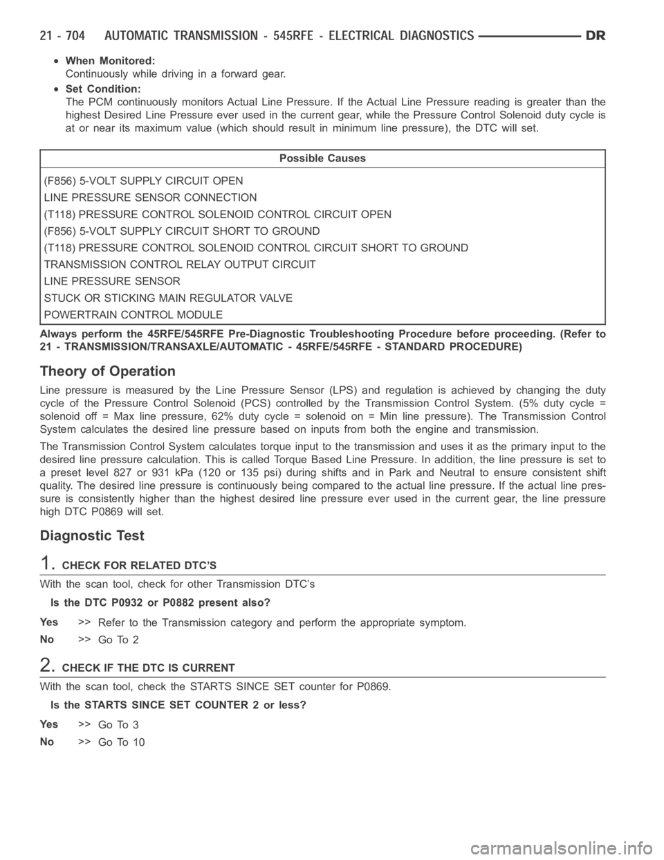
When Monitored:
Continuously while driving in a forward gear.
Set Condition:
The PCM continuously monitors Actual Line Pressure. If the Actual Line Pressure reading is greater than the
highest Desired Line Pressure ever used in the current gear, while the Pressure Control Solenoid duty cycle is
at or near its maximum value (which should result in minimum line pressure), the DTC will set.
Possible Causes
(F856) 5-VOLT SUPPLY CIRCUIT OPEN
LINE PRESSURE SENSOR CONNECTION
(T118) PRESSURE CONTROL SOLENOID CONTROL CIRCUIT OPEN
(F856) 5-VOLT SUPPLY CIRCUIT SHORT TO GROUND
(T118) PRESSURE CONTROL SOLENOID CONTROL CIRCUIT SHORT TO GROUND
TRANSMISSION CONTROL RELAY OUTPUT CIRCUIT
LINE PRESSURE SENSOR
STUCK OR STICKING MAIN REGULATOR VALVE
POWERTRAIN CONTROL MODULE
Always perform the 45RFE/545RFE Pre-Diagnostic Troubleshooting Procedure before proceeding. (Refer to
21 - TRANSMISSION/TRANSAXLE/AUTOMATIC - 45RFE/545RFE - STANDARD PROCEDURE)
Theory of Operation
Line pressure is measured by the Line Pressure Sensor (LPS) and regulationis achieved by changing the duty
cycle of the Pressure Control Solenoid (PCS) controlled by the Transmission Control System. (5% duty cycle =
solenoid off = Max line pressure, 62%duty cycle = solenoid on = Min line pressure). The Transmission Control
System calculates the desired line pressure based on inputs from both the engine and transmission.
The Transmission Control System calculates torque input to the transmission and uses it as the primary input to the
desired line pressure calculation. This is called Torque Based Line Pressure. In addition, the line pressure is set to
a preset level 827 or 931 kPa (120 or 135 psi) during shifts and in Park and Neutral to ensure consistent shift
quality. The desired line pressure is continuously being compared to the actual line pressure. If the actual line pres-
sure is consistently higher than the highest desired line pressure ever used in the current gear, the line pressure
high DTC P0869 will set.
Diagnostic Test
1.CHECKFORRELATEDDTC’S
With the scan tool, check for other Transmission DTC’s
Is the DTC P0932 or P0882 present also?
Ye s>>
Refer to the Transmission category and perform the appropriate symptom.
No>>
Go To 2
2.CHECK IF THE DTC IS CURRENT
With the scan tool, check the STARTS SINCE SET counter for P0869.
Is the STARTS SINCE SET COUNTER 2 or less?
Ye s>>
Go To 3
No>>
Go To 10
Page 3231 of 5267
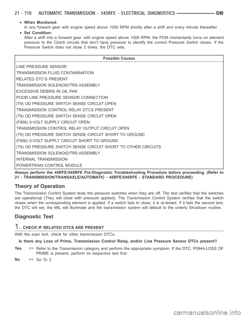
When Monitored:
In any forward gear with engine speed above 1000 RPM shortly after a shift and every minute thereafter.
Set Condition:
After a shift into a forward gear, with engine speed above 1000 RPM, the PCM momentarily turns on element
pressure to the Clutch circuits that don’t have pressure to identify the correct Pressure Switch closes. If the
Pressure Switch does not close 2 times, the DTC sets.
Possible Causes
LINE PRESSURE SENSOR
TRANSMISSION FLUID CONTAMINATION
RELATED DTC’S PRESENT
TRANSMISSION SOLENOID/TRS ASSEMBLY
EXCESSIVE DEBRIS IN OIL PAN
POOR LINE PRESSURE SENSOR CONNECTION
(T9) OD PRESSURE SWITCH SENSE CIRCUIT OPEN
TRANSMISSION CONTROL RELAY DTCS PRESENT
(T9) OD PRESSURE SWITCH SENSE CIRCUIT OPEN
(F856) 5-VOLT SUPPLY CIRCUIT OPEN
TRANSMISSION CONTROL RELAY OUTPUT CIRCUIT OPEN
(T9) OD PRESSURE SWITCH SENSE CIRCUIT SHORT TO GROUND
(F856) 5-VOLT SUPPLY CIRCUIT SHORT TO GROUND
(T9) OD PRESSURE SWITCH SENSE CIRCUIT SHORT TO OTHER CIRCUITS
TRANSMISSION SOLENOID/TRS ASSEMBLY
INTERNAL TRANSMISSION
POWERTRAIN CONTROL MODULE
Always perform the 45RFE/545RFE Pre-Diagnostic Troubleshooting Procedure before proceeding. (Refer to
21 - TRANSMISSION/TRANSAXLE/AUTOMATIC - 45RFE/545RFE - STANDARD PROCEDURE)
Theory of Operation
The Transmission Control System tests the pressure switches when they areoff. The test verifies that the switches
are operational (They will close with pressure applied). The Transmission Control System verifies that the switch
closes when the corresponding element is applied. If a switch fails to close, it is re-tested. If it fails the second test,
the DTC will set, the MIL will illuminate and the transmission system will default to the orderly Shutdown routine.
Diagnostic Test
1.CHECK IF RELATED DTCS ARE PRESENT
With the scan tool, check for other transmission DTCs.
Is there any Loss of Prime, Transmission Control Relay, and/or Line Pressure Sensor DTCs present?
Ye s>>
Refer to the Transmission category and perform the appropriate symptom. If the DTC, P0944-LOSS OF
PRIME is present, perform its respective test first.
No>>
Go To 2