radiator DODGE RAM SRT-10 2006 Service User Guide
[x] Cancel search | Manufacturer: DODGE, Model Year: 2006, Model line: RAM SRT-10, Model: DODGE RAM SRT-10 2006Pages: 5267, PDF Size: 68.7 MB
Page 1518 of 5267
7. Remove the master cylinder and booster assembly (Refer to 5 - BRAKES/HYDRAULIC/MECHANICAL/POWER
BRAKE BOOSTER - REMOVAL).
8. Remove the cylinder head cover (Refer to 9 - ENGINE/CYLINDER HEAD/CYLINDER HEAD COVER(S) -
REMOVAL).
9. Remove the fan shroud and fan blade assembly
(Refer to 7 - COOLING/ENGINE/RADIATOR FAN -
REMOVAL).
10. Remove accessory drive belt (Refer to 7 - COOL-
ING/ACCESSORY DRIVE/DRIVE BELTS -
REMOVAL).
11. Remove the power steering pump and set aside.
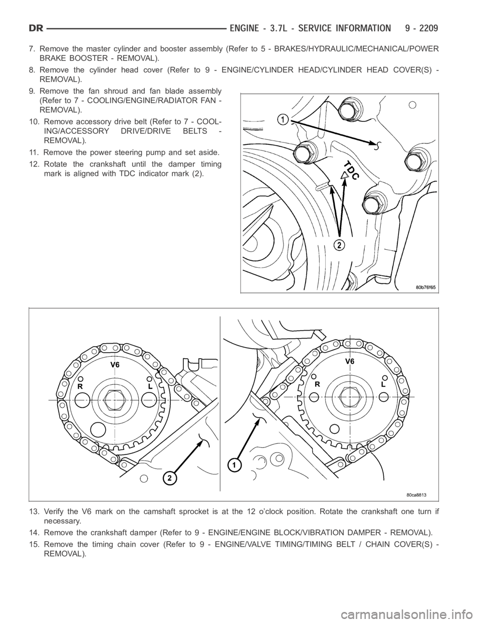
12. Rotate the crankshaft until the damper timing
mark is aligned with TDC indicator mark (2).
13. Verify the V6 mark on the camshaft sprocket is at the 12 o’clock position. Rotate the crankshaft one turn if
necessary.
14. Remove the crankshaft damper (Refer to 9 - ENGINE/ENGINE BLOCK/VIBRATION DAMPER - REMOVAL).
15. Remove the timing chain cover (Refer to 9 - ENGINE/VALVE TIMING/TIMINGBELT / CHAIN COVER(S) -
REMOVAL).
Page 1521 of 5267
2. Position the new cylinder head gasket on the locat-
ing dowels.
CAUTION: When installing cylinder head, use care
not damage the tensioner arm or the guide arm.
3. Position the cylinder head onto the cylinder block.
Make sure the cylinder head seats fully over the
locating dowels.
NOTE: The four smaller cylinder head mounting
bolts require sealant to be added to them before
installing. Failure to do so may cause leaks.
4. Lubricate the cylinder head bolt threads with clean
engine oil and install the eight M11 bolts.
5. Coat the four M8 cylinder head bolts withMopar
Lock and Seal Adhesivethen install the bolts.
NOTE: The cylinder head bolts are tightened using
an angle torque procedure, however, the bolts are
not a torque-to-yield design.
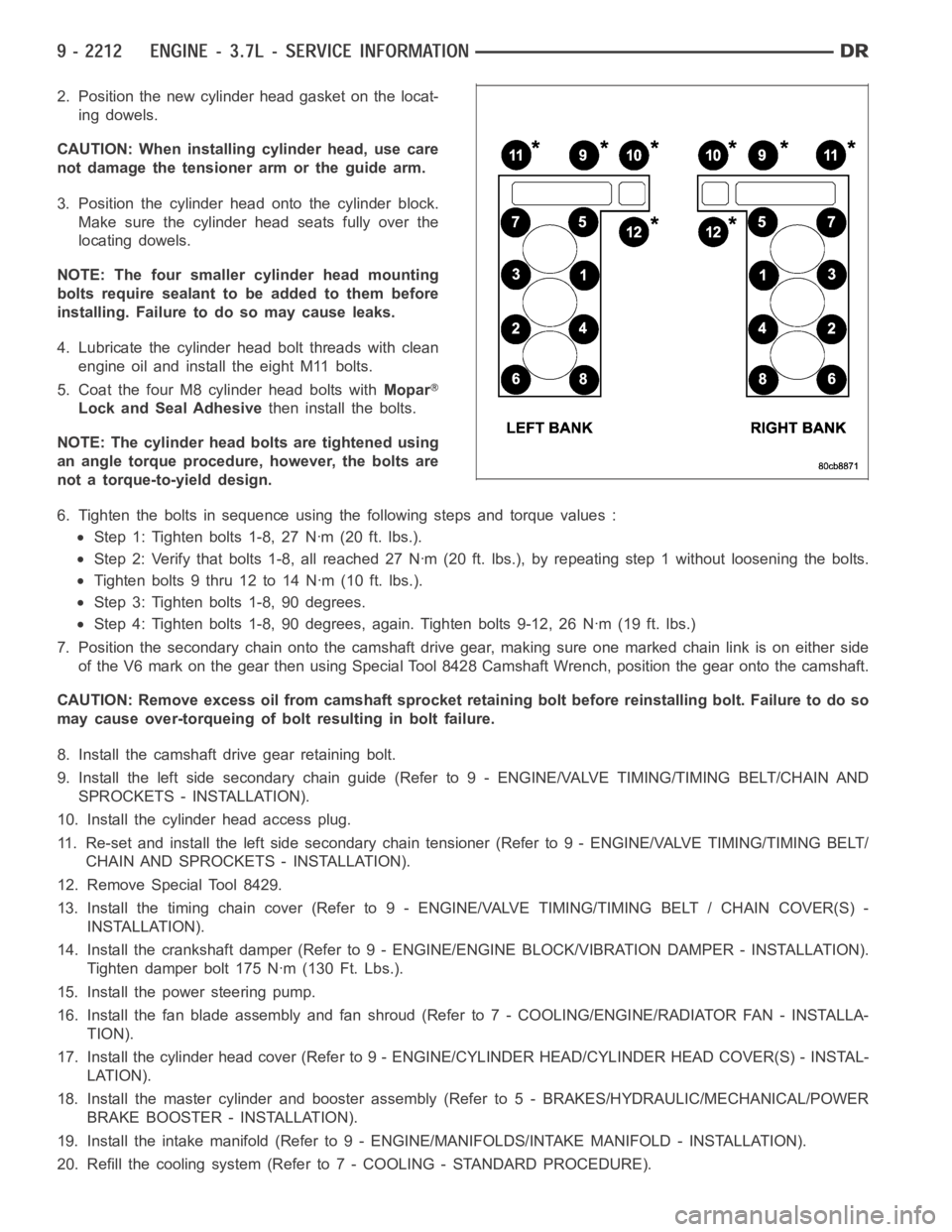
6. Tighten the bolts in sequence using the following steps and torque values:
Step 1: Tighten bolts 1-8, 27 Nꞏm (20 ft. lbs.).
Step 2: Verify that bolts 1-8, all reached 27 Nꞏm (20 ft. lbs.), by repeatingstep 1 without loosening the bolts.
Tightenbolts9thru12to14Nꞏm(10ft.lbs.).
Step 3: Tighten bolts 1-8, 90 degrees.
Step 4: Tighten bolts 1-8, 90 degrees, again. Tighten bolts 9-12, 26 Nꞏm (19ft. lbs.)
7. Position the secondary chain onto the camshaft drive gear, making sure one marked chain link is on either side
of the V6 mark on the gear then using Special Tool 8428 Camshaft Wrench, position the gear onto the camshaft.
CAUTION: Remove excess oil from camshaft sprocket retaining bolt before reinstalling bolt. Failure to do so
may cause over-torqueing of bolt resulting in bolt failure.
8. Install the camshaft drive gear retaining bolt.
9. Install the left side secondary chain guide (Refer to 9 - ENGINE/VALVE TIMING/TIMING BELT/CHAIN AND
SPROCKETS - INSTALLATION).
10. Install the cylinder head access plug.
11. Re-set and install the left side secondary chain tensioner (Refer to 9 -ENGINE/VALVE TIMING/TIMING BELT/
CHAIN AND SPROCKETS - INSTALLATION).
12. Remove Special Tool 8429.
13. Install the timing chain cover (Refer to 9 - ENGINE/VALVE TIMING/TIMING BELT / CHAIN COVER(S) -
INSTALLATION).
14. Install the crankshaft damper (Refer to 9 - ENGINE/ENGINE BLOCK/VIBRATION DAMPER - INSTALLATION).
Tighten damper bolt 175 Nꞏm (130 Ft. Lbs.).
15. Install the power steering pump.
16. Install the fan blade assembly and fan shroud (Refer to 7 - COOLING/ENGINE/RADIATOR FAN - INSTALLA-
TION).
17. Install the cylinder head cover (Refer to 9 - ENGINE/CYLINDER HEAD/CYLINDER HEAD COVER(S) - INSTAL-
LATION).
18. Install the master cylinder and booster assembly (Refer to 5 - BRAKES/HYDRAULIC/MECHANICAL/POWER
BRAKE BOOSTER - INSTALLATION).
19. Install the intake manifold (Refer to 9 - ENGINE/MANIFOLDS/INTAKE MANIFOLD - INSTALLATION).
20. Refill the cooling system (Refer to 7 - COOLING - STANDARD PROCEDURE).
Page 1536 of 5267
HEAD-CYLINDER-RIGHT
DIAGNOSIS AND TESTING - HYDRAULIC LASH ADJUSTER
A tappet-like noise may be produced from several items. Check the followingitems.
1. Engine oil level too high or too low. This may cause aerated oil to enter the adjusters and cause them to be
spongy.
2. Insufficient running time after rebuilding cylinder head. Low speed runningupto1hourmayberequired.
3. Turn engine off and let set for a few minutes before restarting. Repeat this several times after engine has
reached normal operating temperature.
4. Low oil pressure.
5. The oil restrictor in cylinder head gasket or the oil passage to the cylinder head is plugged with debris.
6. Airingestedintooilduetobrokenorcrackedoilpumppickup.
7. Worn valve guides.
8. Rocker arm ears contacting valve spring retainer.
9. Rocker arm loose, adjuster stuck or at maximum extension and still leaves lash in the system.
10. Oil leak or excessive cam bore wear in cylinder head.
11. Faulty lash adjuster.
a. Check lash adjusters for sponginess while installed in cylinder head and cam on camshaft at base circle.
Depress part of rocker arm over adjuster. Normal adjusters should feel firm when pressed quickly. When pressed
very slowly, lash adjusters should collapse.
b. Remove suspected lash adjusters, and replace.
c. Before installation, make sure adjusters are full of oil. This can be verified by little plunger travel when lash
adjuster is depressed quickly.
REMOVAL
REMOVAL RIGHT CYLINDER HEAD
1. Disconnect battery negative cable.
2. Raise the vehicle on a hoist.
3. Disconnect the exhaust pipe at the right side
exhaust manifold.
4. Drain the engine coolant (Refer to 7 - COOLING -
STANDARD PROCEDURE).
5. Lower the vehicle.
6. Remove the intake manifold (Refer to 9 - ENGINE/
MANIFOLDS/INTAKE MANIFOLD - REMOVAL).
7. Remove the cylinder head cover (Refer to 9 -
ENGINE/CYLINDER HEAD - REMOVAL).
8. Remove the fan shroud (Refer to 7 - COOLING/
ENGINE/RADIATOR FAN - REMOVAL).
9. Remove oil fill housing from cylinder head.
10. Remove accessory drive belt (Refer to 7 - COOL-
ING/ACCESSORY DRIVE/DRIVE BELTS -
REMOVAL).
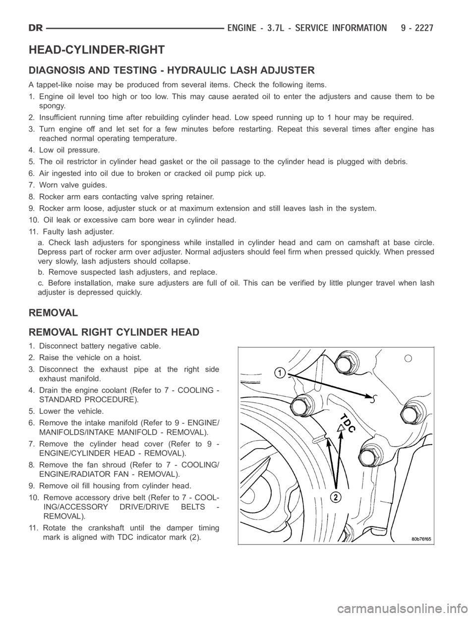
11. Rotate the crankshaft until the damper timing
mark is aligned with TDC indicator mark (2).
Page 1542 of 5267
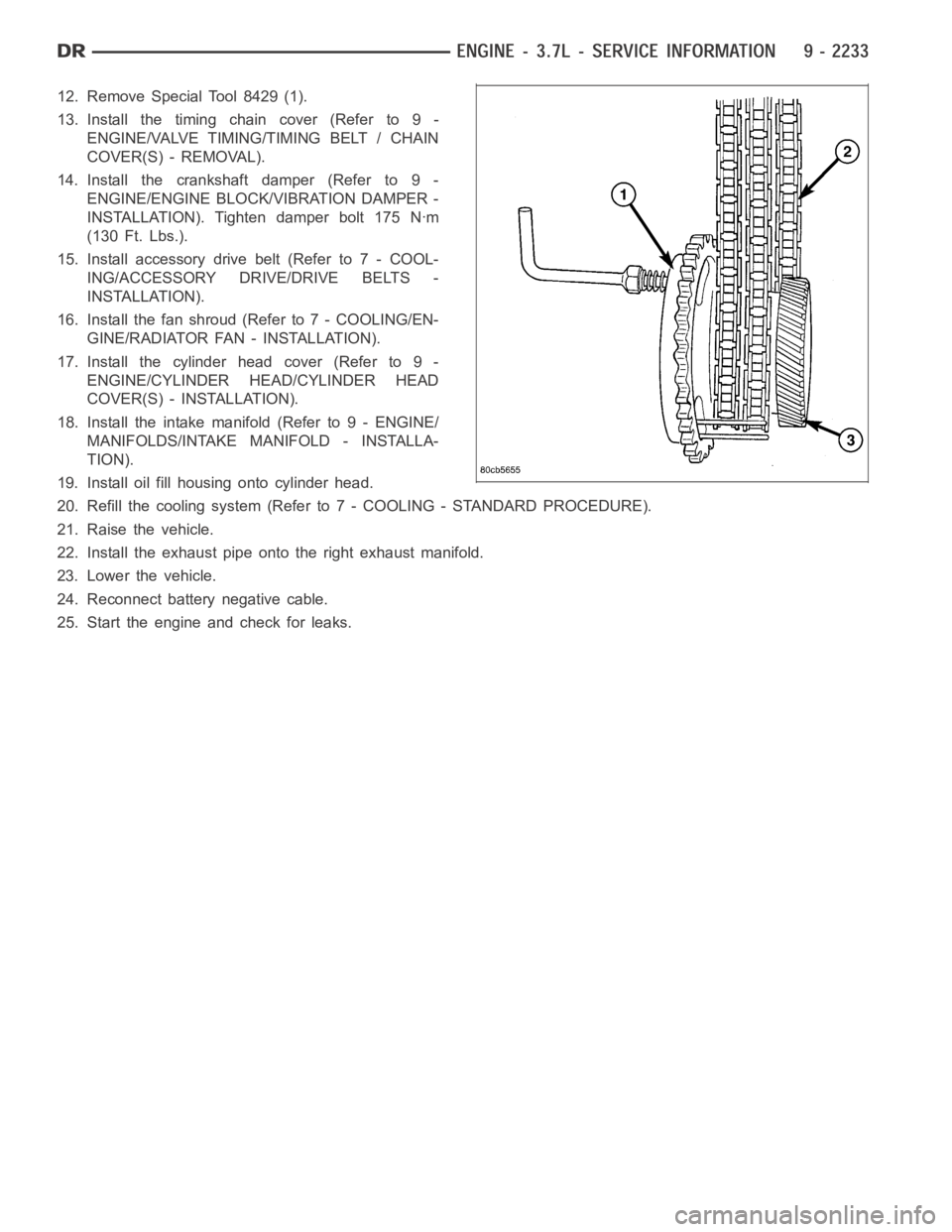
12. Remove Special Tool 8429 (1).
13. Install the timing chain cover (Refer to 9 -
ENGINE/VALVE TIMING/TIMING BELT / CHAIN
COVER(S) - REMOVAL).
14. Install the crankshaft damper (Refer to 9 -
ENGINE/ENGINE BLOCK/VIBRATION DAMPER -
INSTALLATION). Tighten damper bolt 175 Nꞏm
(130 Ft. Lbs.).
15. Install accessory drive belt (Refer to 7 - COOL-
ING/ACCESSORY DRIVE/DRIVE BELTS -
INSTALLATION).
16. Install the fan shroud (Refer to 7 - COOLING/EN-
GINE/RADIATOR FAN - INSTALLATION).
17. Install the cylinder head cover (Refer to 9 -
ENGINE/CYLINDER HEAD/CYLINDER HEAD
COVER(S) - INSTALLATION).
18. Install the intake manifold (Refer to 9 - ENGINE/
MANIFOLDS/INTAKE MANIFOLD - INSTALLA-
TION).
19. Install oil fill housing onto cylinder head.
20. Refill the cooling system (Refer to 7 - COOLING - STANDARD PROCEDURE).
21. Raise the vehicle.
22. Install the exhaust pipe onto the right exhaust manifold.
23. Lower the vehicle.
24. Reconnect battery negative cable.
25. Start the engine and check for leaks.
Page 1562 of 5267
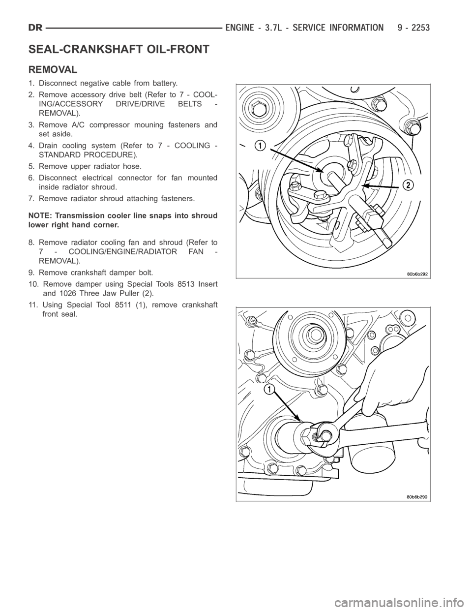
SEAL-CRANKSHAFT OIL-FRONT
REMOVAL
1. Disconnect negative cable from battery.
2. Remove accessory drive belt (Refer to 7 - COOL-
ING/ACCESSORY DRIVE/DRIVE BELTS -
REMOVAL).
3. Remove A/C compressor mouning fasteners and
set aside.
4. Drain cooling system (Refer to 7 - COOLING -
STANDARD PROCEDURE).
5. Remove upper radiator hose.
6. Disconnect electrical connector for fan mounted
inside radiator shroud.
7. Remove radiator shroud attaching fasteners.
NOTE: Transmission cooler line snaps into shroud
lower right hand corner.
8. Remove radiator cooling fan and shroud (Refer to
7 - COOLING/ENGINE/RADIATOR FAN -
REMOVAL).
9. Remove crankshaft damper bolt.
10. Remove damper using Special Tools 8513 Insert
and 1026 Three Jaw Puller (2).
11. Using Special Tool 8511 (1), remove crankshaft
front seal.
Page 1563 of 5267
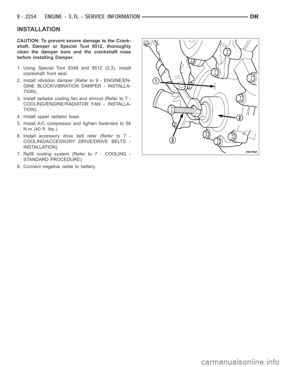
INSTALLATION
CAUTION: To prevent severe damage to the Crank-
shaft, Damper or Special Tool 8512, thoroughly
clean the damper bore and the crankshaft nose
before installing Damper.
1. Using Special Tool 8348 and 8512 (2,3), install
crankshaft front seal.
2. Install vibration damper (Refer to 9 - ENGINE/EN-
GINE BLOCK/VIBRATION DAMPER - INSTALLA-
TION).
3. Installradiatorcoolingfanandshroud(Referto7-
COOLING/ENGINE/RADIATOR FAN - INSTALLA-
TION).
4. Install upper radiator hose.
5. Install A/C compressor and tighten fasteners to 54
Nꞏm (40 ft. lbs.).
6. Install accessory drive belt refer (Refer to 7 -
COOLING/ACCESSORY DRIVE/DRIVE BELTS -
INSTALLATION).
7. Refill cooling system (Refer to 7 - COOLING -
STANDARD PROCEDURE).
8. Connect negative cable to battery.
Page 1577 of 5267
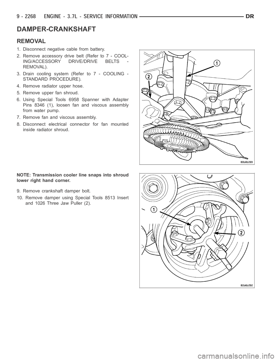
DAMPER-CRANKSHAFT
REMOVAL
1. Disconnect negative cable from battery.
2. Remove accessory drive belt (Refer to 7 - COOL-
ING/ACCESSORY DRIVE/DRIVE BELTS -
REMOVAL).
3. Drain cooling system (Refer to 7 - COOLING -
STANDARD PROCEDURE).
4. Remove radiator upper hose.
5. Remove upper fan shroud.
6. Using Special Tools 6958 Spanner with Adapter
Pins 8346 (1), loosen fan and viscous assembly
from water pump.
7. Remove fan and viscous assembly.
8. Disconnect electrical connector for fan mounted
inside radiator shroud.
NOTE: Transmission cooler line snaps into shroud
lower right hand corner.
9. Remove crankshaft damper bolt.
10. Remove damper using Special Tools 8513 Insert
and 1026 Three Jaw Puller (2).
Page 1578 of 5267
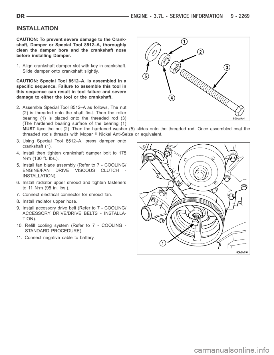
INSTALLATION
CAUTION: To prevent severe damage to the Crank-
shaft, Damper or Special Tool 8512–A, thoroughly
clean the damper bore and the crankshaft nose
before installing Damper.
1. Align crankshaft damper slot with key in crankshaft.
Slide damper onto crankshaft slightly.
CAUTION: Special Tool 8512–A, is assembled in a
specific sequence. Failure to assemble this tool in
this sequence can result in tool failure and severe
damage to either the tool or the crankshaft.
2. Assemble Special Tool 8512–A as follows, The nut
(2) is threaded onto the shaft first. Then the roller
bearing (1) is placed onto the threaded rod (3)
(The hardened bearing surface of the bearing (1)
MUSTface the nut (2). Then the hardened washer (5) slides onto the threaded rod.Once assembled coat the
threaded rod’s threads with Mopar
Nickel Anti-Seize or equivalent.
3. Using Special Tool 8512–A, press damper onto
crankshaft (1).
4. Install then tighten crankshaft damper bolt to 175
Nꞏm (130 ft. lbs.).
5. Install fan blade assembly (Refer to 7 - COOLING/
ENGINE/FAN DRIVE VISCOUS CLUTCH -
INSTALLATION).
6. Install radiator upper shroud and tighten fasteners
to 11 Nꞏm (95 in. lbs.).
7. Connect electrical connector for shroud fan.
8. Install radiator upper hose.
9. Install accessory drive belt (Refer to 7 - COOLING/
ACCESSORY DRIVE/DRIVE BELTS - INSTALLA-
TION).
10. Refill cooling system (Refer to 7 - COOLING -
STANDARD PROCEDURE).
11. Connect negative cable to battery.
Page 1613 of 5267
SHAFT-IDLER
REMOVAL
1. Remove the primary and secondary timing chains and sprockets. Refer to procedure in this section.
NOTE: To remove the idler shaft, it is necessary to tap threads into the shaft, to install the removal tool.
2. Using a 12 mm X 1.75 tap, cut threads in the idler shaft center bore.
3. Cover the radiator core with a suitable cover.
CAUTION: Use care when removing the idler shaft, Do not strike the radiatorcooling fins with the slide
hammer.
4. Using Special Tool 8517 Slide Hammer, remove the idler shaft.
INSTALLATION
1. Thoroughly clean the idler shaft bore.
2. Position the idler shaft in the bore.
NOTE: The two lubrication holes in the idler shaft do not require any specialalignment.
NOTE: Before using the retaining bolt to install the idler shaft, coat the threads and the pilot on the idler
shaft, with clean engine oil.
3. Using the primary idler sprocket retaining bolt and washer, carefully draw the idler shaft into the bore until fully
seated.
4. Coat the idler shaft with clean engine oil.
5. Install the timing chains and sprockets. Refer to procedure in this section.
Page 1614 of 5267
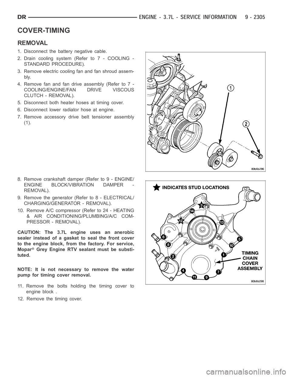
COVER-TIMING
REMOVAL
1. Disconnect the battery negative cable.
2. Drain cooling system (Refer to 7 - COOLING -
STANDARD PROCEDURE).
3. Remove electric cooling fan and fan shroud assem-
bly.
4. Remove fan and fan drive assembly (Refer to 7 -
COOLING/ENGINE/FAN DRIVE VISCOUS
CLUTCH - REMOVAL).
5. Disconnect both heater hoses at timing cover.
6. Disconnect lower radiator hose at engine.
7. Remove accessory drive belt tensioner assembly
(1).
8. Remove crankshaft damper (Refer to 9 - ENGINE/
ENGINE BLOCK/VIBRATION DAMPER -
REMOVAL).
9. Remove the generator (Refer to 8 - ELECTRICAL/
CHARGING/GENERATOR - REMOVAL).
10. Remove A/C compressor (Refer to 24 - HEATING
& AIR CONDITIONING/PLUMBING/A/C COM-
PRESSOR - REMOVAL).
CAUTION: The 3.7L engine uses an anerobic
sealer instead of a gasket to seal the front cover
to the engine block, from the factory. For service,
Mopar
Grey Engine RTV sealant must be substi-
tuted.
NOTE: It is not necessary to remove the water
pump for timing cover removal.
11. Remove the bolts holding the timing cover to
engine block .
12. Remove the timing cover.