radiator DODGE RAM SRT-10 2006 Service Service Manual
[x] Cancel search | Manufacturer: DODGE, Model Year: 2006, Model line: RAM SRT-10, Model: DODGE RAM SRT-10 2006Pages: 5267, PDF Size: 68.7 MB
Page 1835 of 5267
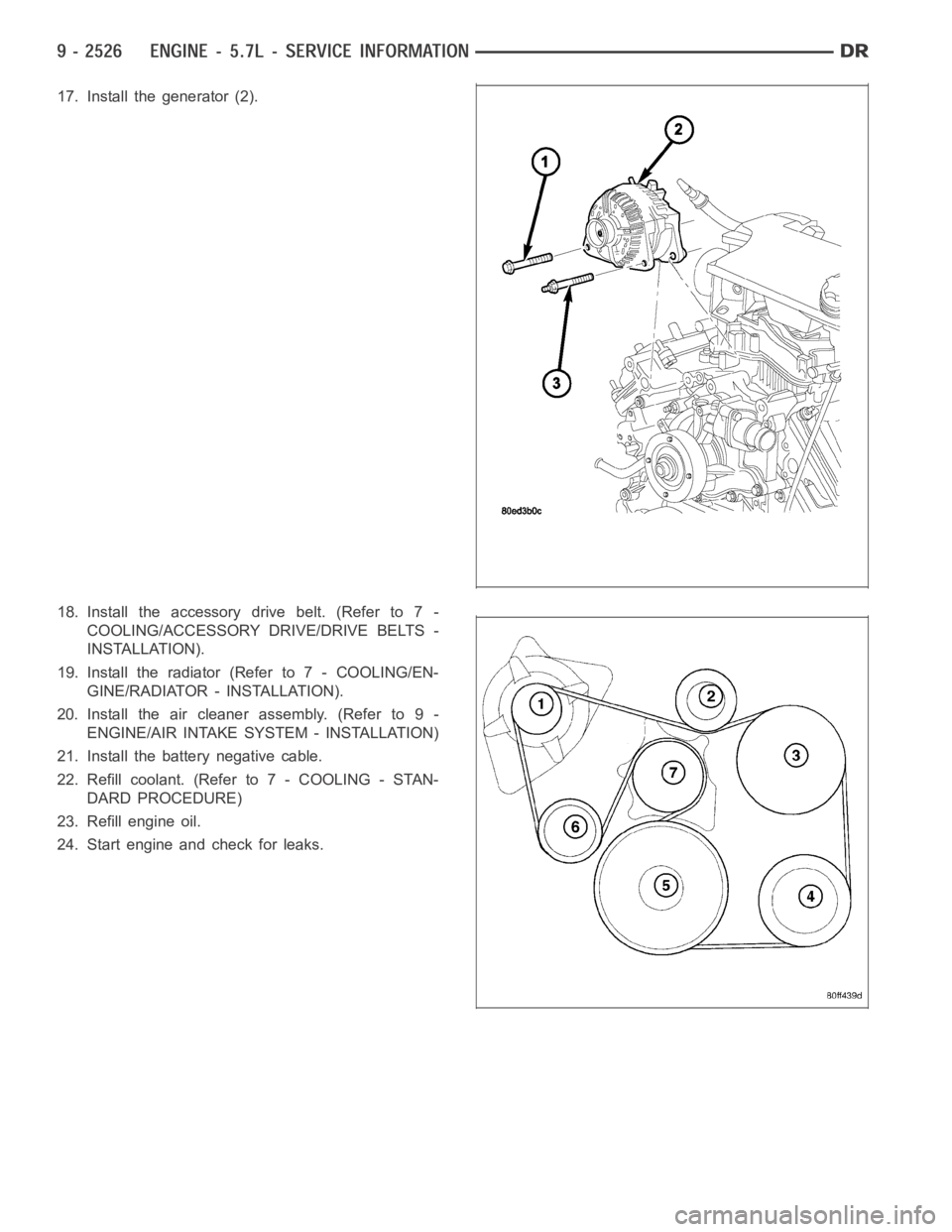
17. Install the generator (2).
18. Install the accessory drive belt. (Refer to 7 -
COOLING/ACCESSORY DRIVE/DRIVE BELTS -
INSTALLATION).
19. Install the radiator (Refer to 7 - COOLING/EN-
GINE/RADIATOR - INSTALLATION).
20. Install the air cleaner assembly. (Refer to 9 -
ENGINE/AIR INTAKE SYSTEM - INSTALLATION)
21. Install the battery negative cable.
22. Refill coolant. (Refer to 7 - COOLING - STAN-
DARD PROCEDURE)
23. Refill engine oil.
24. Start engine and check for leaks.
Page 1846 of 5267
SEAL - CRANKSHAFT OIL - FRONT
REMOVAL
1. Disconnect negative cable from battery.
2. Remove accessory drive belt (Refer to 7 - COOL-
ING/ACCESSORY DRIVE/DRIVE BELTS -
REMOVAL).
3. Drain cooling system (Refer to 7 - COOLING -
STANDARD PROCEDURE).
4. Remove upper radiator hose.
5. Remove radiator shroud attaching fasteners.
6. Remove radiator cooling fan and shroud (Refer to
7 - COOLING/ENGINE/RADIATOR FAN -
REMOVAL).
7. Remove crankshaft damper bolt.
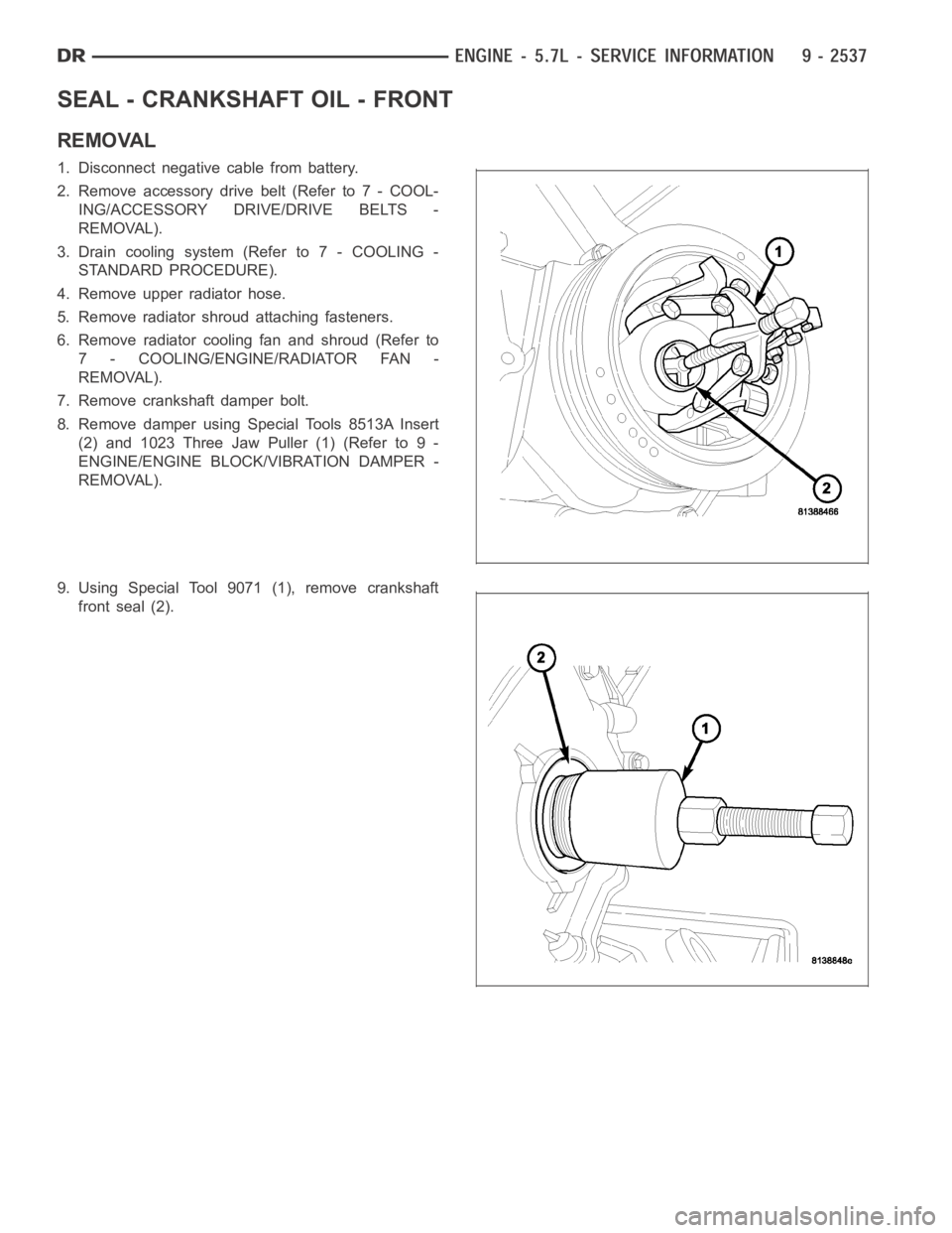
8. Remove damper using Special Tools 8513A Insert
(2) and 1023 Three Jaw Puller (1) (Refer to 9 -
ENGINE/ENGINE BLOCK/VIBRATION DAMPER -
REMOVAL).
9. Using Special Tool 9071 (1), remove crankshaft
front seal (2).
Page 1847 of 5267
INSTALLATION
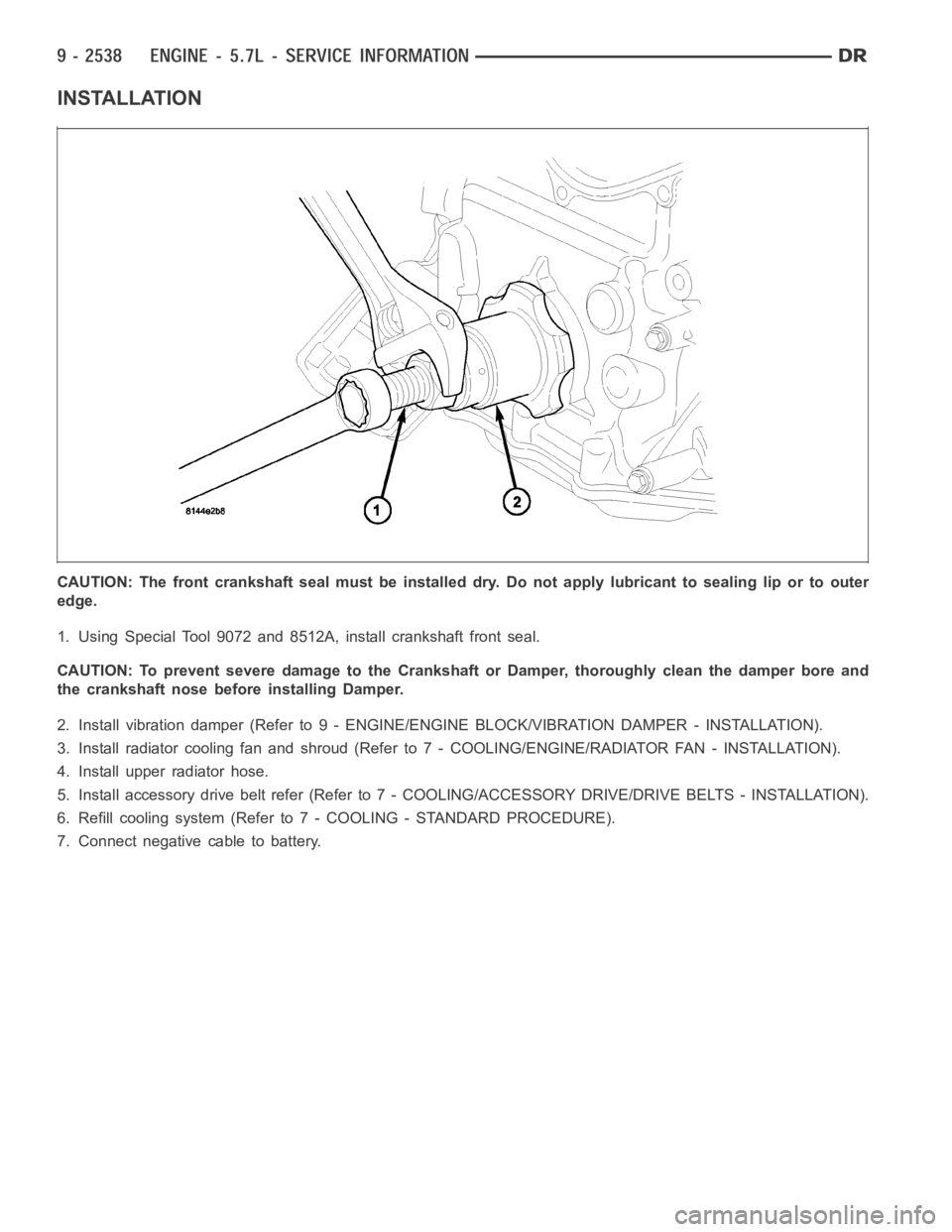
CAUTION: The front crankshaft seal must be installed dry. Do not apply lubricant to sealing lip or to outer
edge.
1. Using Special Tool 9072 and 8512A, install crankshaft front seal.
CAUTION: To prevent severe damage to the Crankshaft or Damper, thoroughlyclean the damper bore and
the crankshaft nose before installing Damper.
2. Install vibration damper (Refer to 9 - ENGINE/ENGINE BLOCK/VIBRATION DAMPER - INSTALLATION).
3. Install radiator cooling fan and shroud (Refer to 7 - COOLING/ENGINE/RADIATOR FAN - INSTALLATION).
4. Install upper radiator hose.
5. Install accessory drive belt refer (Refer to 7 - COOLING/ACCESSORY DRIVE/DRIVE BELTS - INSTALLATION).
6. Refill cooling system (Refer to 7 - COOLING - STANDARD PROCEDURE).
7. Connect negative cable to battery.
Page 1863 of 5267
DAMPER - CRANKSHAFT
REMOVAL
1. Disconnect negative cable from battery.
2. Remove accessory drive belt (Refer to 7 - COOLING/ACCESSORY DRIVE/DRIVE BELTS - REMOVAL).
3. Drain cooling system (Refer to 7 - COOLING - STANDARD PROCEDURE).
4. Remove radiator upper hose.
5. Removefanshroud(Referto7-COOLING/ENGINE/RADIATOR FAN - REMOVAL).
6. Remove crankshaft damper bolt.
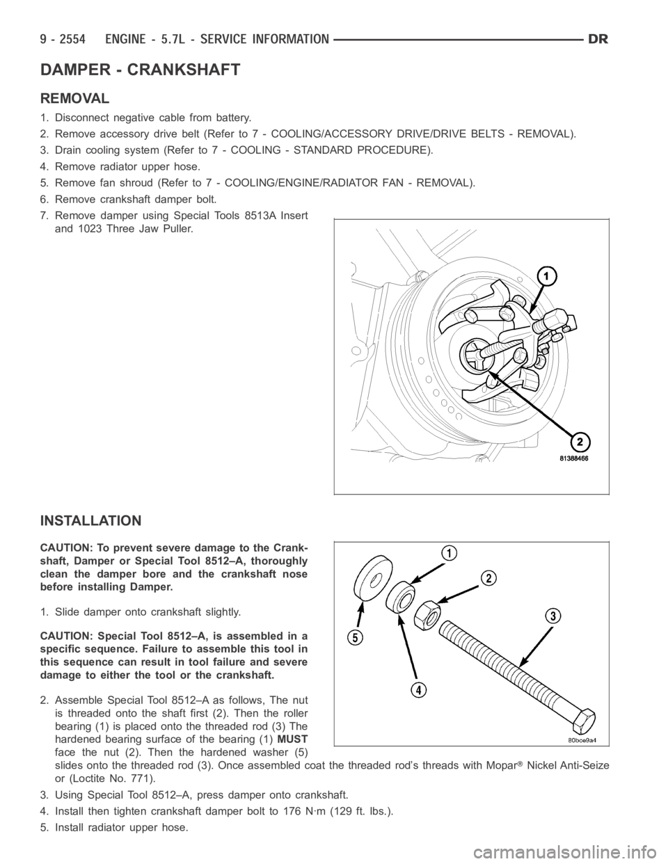
7. Remove damper using Special Tools 8513A Insert
and 1023 Three Jaw Puller.
INSTALLATION
CAUTION: To prevent severe damage to the Crank-
shaft, Damper or Special Tool 8512–A, thoroughly
clean the damper bore and the crankshaft nose
before installing Damper.
1. Slide damper onto crankshaft slightly.
CAUTION: Special Tool 8512–A, is assembled in a
specific sequence. Failure to assemble this tool in
this sequence can result in tool failure and severe
damage to either the tool or the crankshaft.
2. Assemble Special Tool 8512–A as follows, The nut
is threaded onto the shaft first (2). Then the roller
bearing (1) is placed onto the threaded rod (3) The
hardened bearing surface of the bearing (1)MUST
face the nut (2). Then the hardened washer (5)
slides onto the threaded rod (3). Once assembled coat the threaded rod’s threads with Mopar
Nickel Anti-Seize
or (Loctite No. 771).
3. Using Special Tool 8512–A, press damper onto crankshaft.
4. Install then tighten crankshaft damper bolt to 176 Nꞏm (129 ft. lbs.).
5. Install radiator upper hose.
Page 1892 of 5267
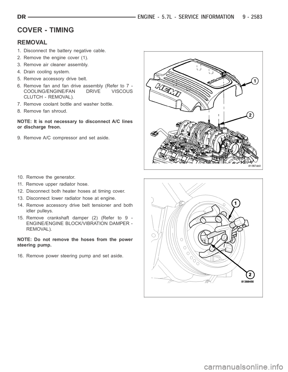
COVER - TIMING
REMOVAL
1. Disconnect the battery negative cable.
2. Remove the engine cover (1).
3. Remove air cleaner assembly.
4. Drain cooling system.
5. Remove accessory drive belt.
6. Remove fan and fan drive assembly (Refer to 7 -
COOLING/ENGINE/FAN DRIVE VISCOUS
CLUTCH - REMOVAL).
7. Remove coolant bottle and washer bottle.
8. Remove fan shroud.
NOTE: It is not necessary to disconnect A/C lines
or discharge freon.
9. Remove A/C compressor and set aside.
10. Remove the generator.
11. Remove upper radiator hose.
12. Disconnect both heater hoses at timing cover.
13. Disconnect lower radiator hose at engine.
14. Remove accessory drive belt tensioner and both
idler pulleys.
15. Remove crankshaft damper (2) (Refer to 9 -
ENGINE/ENGINE BLOCK/VIBRATION DAMPER -
REMOVAL).
NOTE: Do not remove the hoses from the power
steering pump.
16. Remove power steering pump and set aside.
Page 1895 of 5267
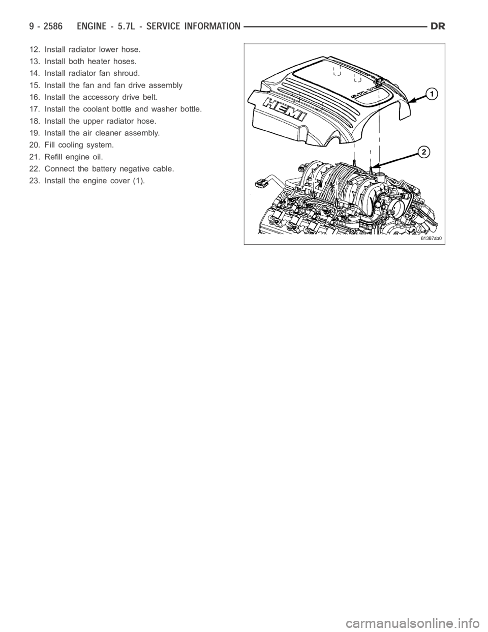
12. Install radiator lower hose.
13. Install both heater hoses.
14. Install radiator fan shroud.
15. Install the fan and fan drive assembly
16. Install the accessory drive belt.
17. Install the coolant bottle and washer bottle.
18. Install the upper radiator hose.
19. Install the air cleaner assembly.
20. Fill cooling system.
21. Refill engine oil.
22. Connect the battery negative cable.
23. Install the engine cover (1).
Page 1914 of 5267
3. Place a shop towel around the fuel injectors to catch any fluid that may possibly be under pressure in the cyl-
inder head. Remove the fuel injectors (Refer to 14 - FUEL SYSTEM/FUEL INJECTION/FUEL INJECTOR -
REMOVAL).
4. With all injectors removed, rotatethe crankshaft using the crankshaftbarring tool (PN 7471–B).
5. Identify the fluid in the cylinders (coolant, fuel, oil, etc.).
6. Be sure all fluid has been removed from the cylinders.
7. Repair engine or components as necessary to prevent this problem from occurring again.
8. Squirt a small amount of engine oil into the cylinders to lubricate the walls. This will prevent damage on restart.
9. Install fuel injectors (Refer to 14 - FUEL SYSTEM/FUEL INJECTION/FUEL INJECTOR - INSTALLATION).
10. Drain engine oil. Remove and discard the oil filter (Refer to 9 - ENGINE/LUBRICATION/OIL FILTER -
REMOVAL).
11. Installthedrainplug.Tightentheplugto50Nꞏm(37ft.lbs.)torque.
12. Install a new oil filter (Refer to 9 - ENGINE/LUBRICATION/OIL FILTER - INSTALLATION).
13. Fill engine crankcase with the specified amount and grade of oil (Referto LUBRICATION & MAINTENANCE/
FLUID TYPES - SPECIFICATIONS).
14. Connect the negative cable(s) to the battery.
15. Start the engine and check for any leaks.
REMOVAL - ENGINE
1. Disconnect both battery negative cables.
2. Disconnect engine grid heater harness at grid
heater relays.
3. Disconnect electrical connections from rear of alter-
nator.
4. Recover A/C refrigerant. (Refer to 24 - HEATING &
AIR CONDITIONING/PLUMBING - STANDARD
PROCEDURE).
5. Raise vehicle on a hoist.
6. Drain engine coolant (Refer to 7 - COOLING -
STANDARD PROCEDURE).
7. Remove engine oil drain plug and drain engine oil.
8. Reinstall drain plug. Tighten to 50 Nꞏm (37 ft. lbs.)
torque.
9. Lower the vehicle.
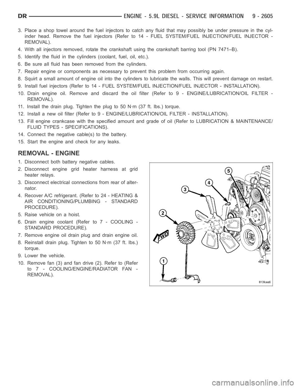
10. Remove fan (3) and fan drive (2). Refer to (Refer
to 7 - COOLING/ENGINE/RADIATOR FAN -
REMOVAL).
Page 1915 of 5267
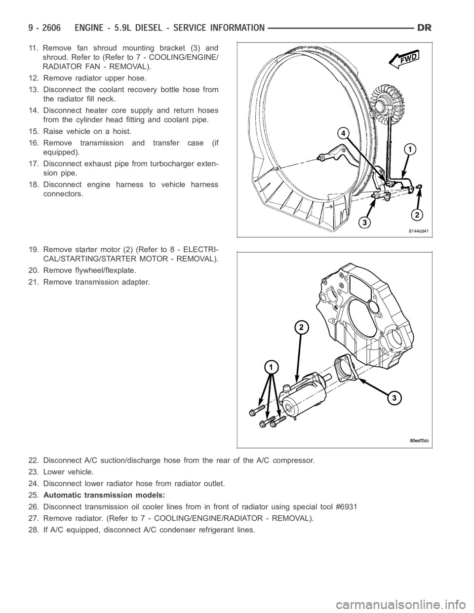
11. Remove fan shroud mounting bracket (3) and
shroud. Refer to (Refer to 7 - COOLING/ENGINE/
RADIATOR FAN - REMOVAL).
12. Remove radiator upper hose.
13. Disconnect the coolant recovery bottle hose from
the radiator fill neck.
14. Disconnect heater core supply and return hoses
from the cylinder head fitting and coolant pipe.
15. Raise vehicle on a hoist.
16. Remove transmission and transfer case (if
equipped).
17. Disconnect exhaust pipe from turbocharger exten-
sion pipe.
18. Disconnect engine harness to vehicle harness
connectors.
19. Remove starter motor (2) (Refer to 8 - ELECTRI-
CAL/STARTING/STARTER MOTOR - REMOVAL).
20. Remove flywheel/flexplate.
21. Remove transmission adapter.
22. Disconnect A/C suction/discharge hose from the rear of the A/C compressor.
23. Lower vehicle.
24. Disconnect lower radiator hose from radiator outlet.
25.Automatic transmission models:
26. Disconnect transmission oil cooler lines from in front of radiator using special tool #6931
27. Remove radiator. (Refer to 7 - COOLING/ENGINE/RADIATOR - REMOVAL).
28. If A/C equipped, disconnect A/C condenser refrigerant lines.
Page 1923 of 5267
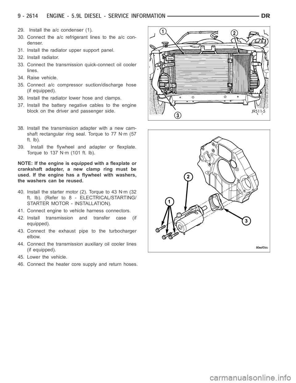
29. Install the a/c condenser (1).
30. Connect the a/c refrigerant lines to the a/c con-
denser.
31. Install the radiator upper support panel.
32. Install radiator.
33. Connect the transmission quick-connect oil cooler
lines.
34. Raise vehicle.
35. Connect a/c compressor suction/discharge hose
(if equipped).
36. Install the radiator lower hose and clamps.
37. Install the battery negative cables to the engine
block on the driver and passenger side.
38. Install the transmission adapter with a new cam-
shaft rectangular ring seal. Torque to 77 Nꞏm (57
ft. lb).
39. Install the flywheel and adapter or flexplate.
Torque to 137 Nꞏm (101 ft. lb).
NOTE: If the engine is equipped with a flexplate or
crankshaft adapter, a new clamp ring must be
used. If the engine has a flywheel with washers,
the washers can be reused.
40. Install the starter motor (2). Torque to 43 Nꞏm (32
ft. lb). (Refer to 8 - ELECTRICAL/STARTING/
STARTER MOTOR - INSTALLATION).
41. Connect engine to vehicle harness connectors.
42. Install transmission and transfer case (if
equipped).
43. Connect the exhaust pipe to the turbocharger
elbow.
44. Connect the transmission auxiliary oil cooler lines
(if equipped).
45. Lower the vehicle.
46. Connect the heater core supply and return hoses.
Page 1924 of 5267
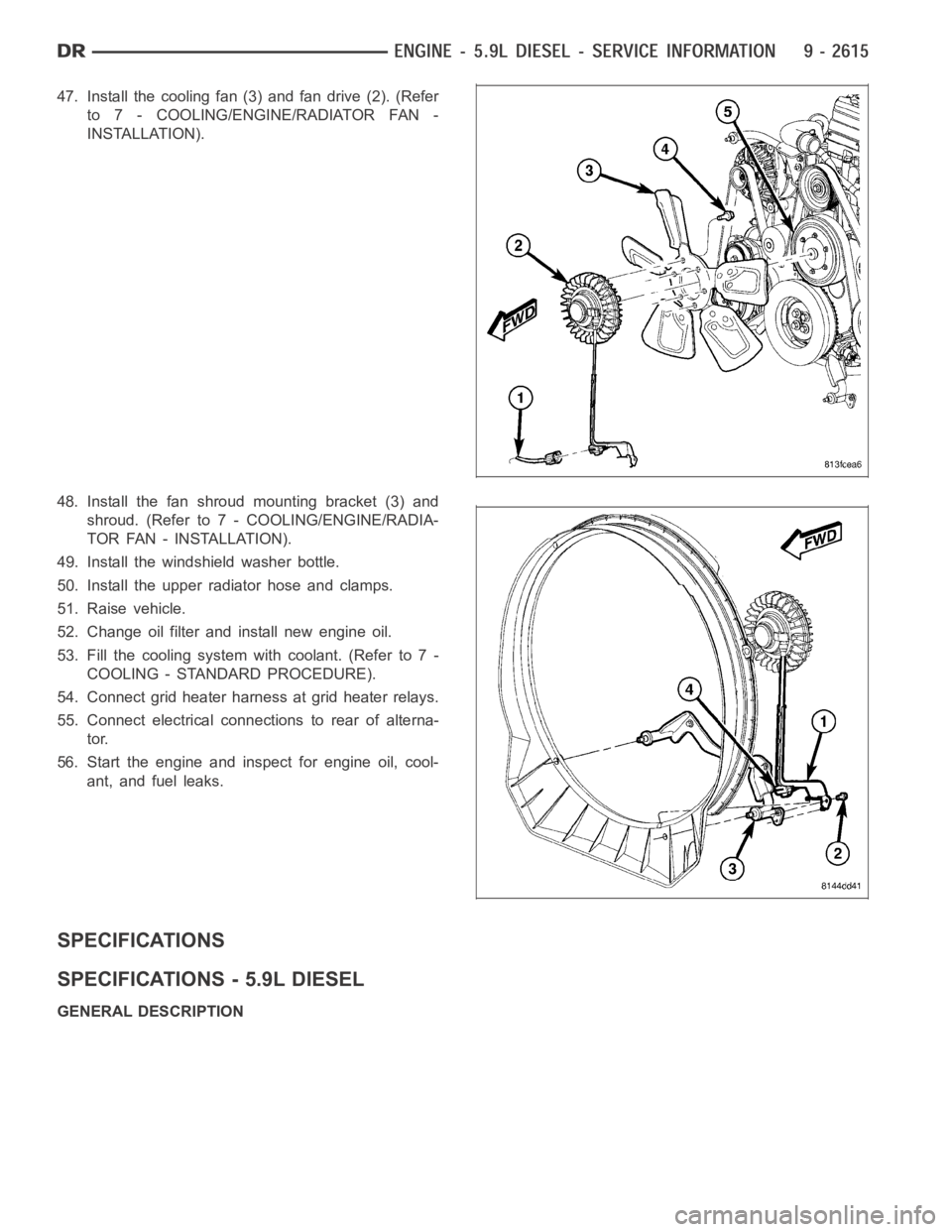
47. Install the cooling fan (3) and fan drive (2). (Refer
to 7 - COOLING/ENGINE/RADIATOR FAN -
INSTALLATION).
48. Install the fan shroud mounting bracket (3) and
shroud. (Refer to 7 - COOLING/ENGINE/RADIA-
TOR FAN - INSTALLATION).
49. Install the windshield washer bottle.
50. Install the upper radiator hose and clamps.
51. Raise vehicle.
52. Change oil filter and install new engine oil.
53. Fill the cooling system with coolant. (Refer to 7 -
COOLING - STANDARD PROCEDURE).
54. Connect grid heater harness at grid heater relays.
55. Connect electrical connections to rear of alterna-
tor.
56. Start the engine and inspect for engine oil, cool-
ant, and fuel leaks.
SPECIFICATIONS
SPECIFICATIONS - 5.9L DIESEL
GENERAL DESCRIPTION