radiator DODGE RAM SRT-10 2006 Service Owner's Manual
[x] Cancel search | Manufacturer: DODGE, Model Year: 2006, Model line: RAM SRT-10, Model: DODGE RAM SRT-10 2006Pages: 5267, PDF Size: 68.7 MB
Page 1615 of 5267
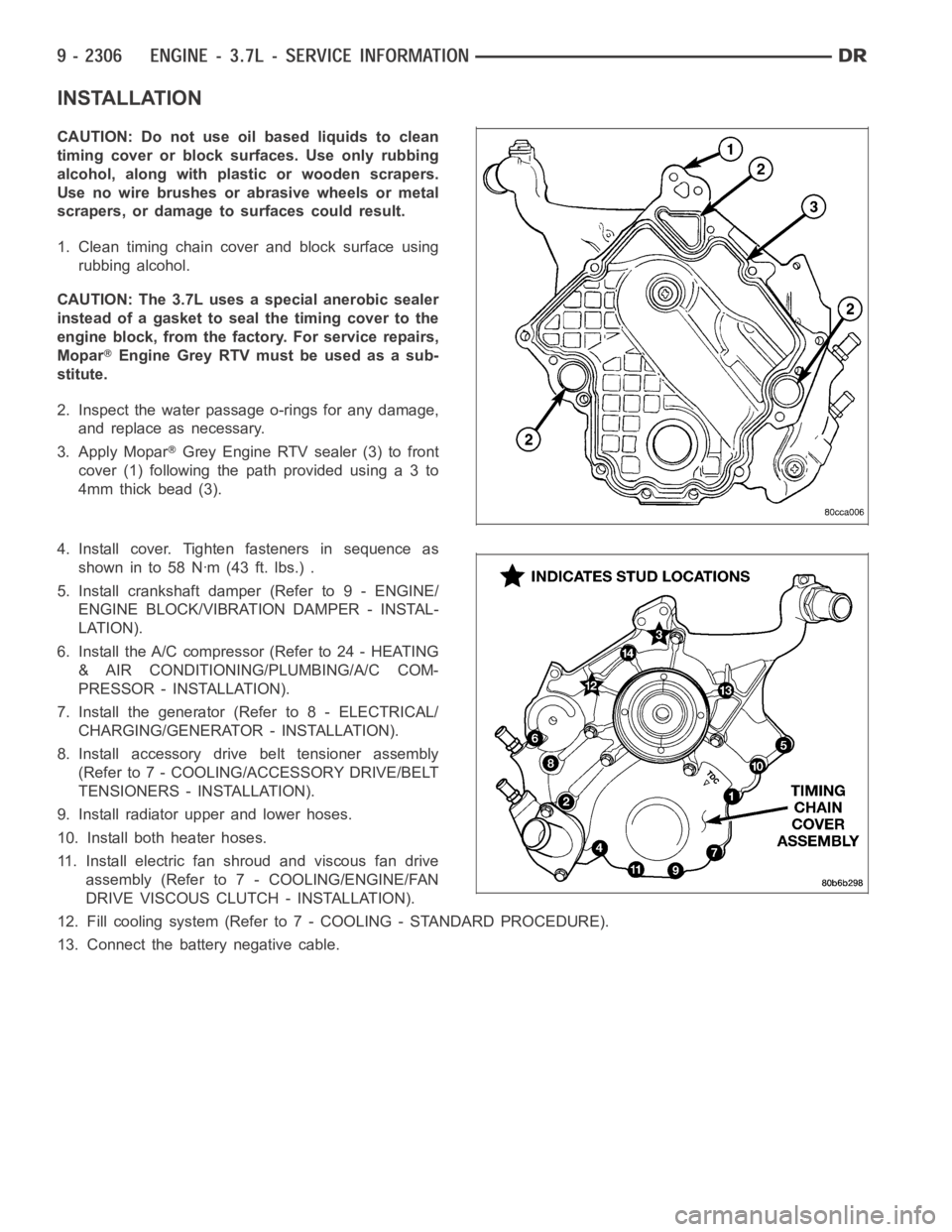
INSTALLATION
CAUTION: Do not use oil based liquids to clean
timing cover or block surfaces. Use only rubbing
alcohol, along with plastic or wooden scrapers.
Use no wire brushes or abrasive wheels or metal
scrapers, or damage to surfaces could result.
1. Clean timing chain cover and block surface using
rubbing alcohol.
CAUTION: The 3.7L uses a special anerobic sealer
instead of a gasket to seal the timing cover to the
engine block, from the factory. For service repairs,
Mopar
Engine Grey RTV must be used as a sub-
stitute.
2. Inspect the water passage o-rings for any damage,
and replace as necessary.
3. Apply Mopar
Grey Engine RTV sealer (3) to front
cover(1)followingthepathprovidedusinga3to
4mm thick bead (3).
4. Install cover. Tighten fasteners in sequence as
showninto58Nꞏm(43ft.lbs.).
5. Install crankshaft damper (Refer to 9 - ENGINE/
ENGINE BLOCK/VIBRATION DAMPER - INSTAL-
LATION).
6. Install the A/C compressor (Refer to 24 - HEATING
& AIR CONDITIONING/PLUMBING/A/C COM-
PRESSOR - INSTALLATION).
7. Install the generator (Refer to 8 - ELECTRICAL/
CHARGING/GENERATOR - INSTALLATION).
8. Install accessory drive belt tensioner assembly
(Refer to 7 - COOLING/ACCESSORY DRIVE/BELT
TENSIONERS - INSTALLATION).
9. Install radiator upper and lower hoses.
10. Install both heater hoses.
11. Install electric fan shroud and viscous fan drive
assembly (Refer to 7 - COOLING/ENGINE/FAN
DRIVE VISCOUS CLUTCH - INSTALLATION).
12. Fill cooling system (Refer to 7 - COOLING - STANDARD PROCEDURE).
13. Connect the battery negative cable.
Page 1616 of 5267
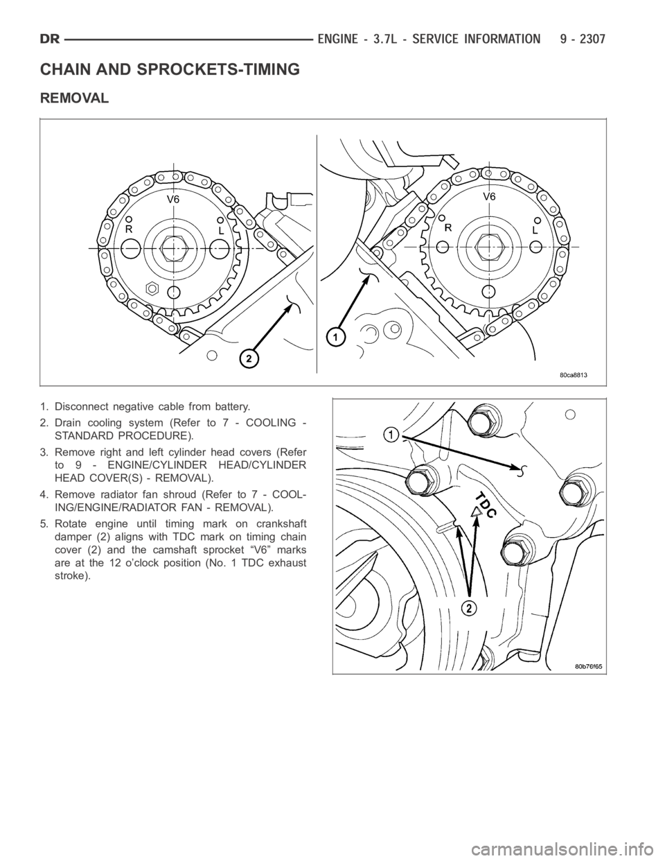
CHAIN AND SPROCKETS-TIMING
REMOVAL
1. Disconnect negative cable from battery.
2. Drain cooling system (Refer to 7 - COOLING -
STANDARD PROCEDURE).
3. Remove right and left cylinder head covers (Refer
to 9 - ENGINE/CYLINDER HEAD/CYLINDER
HEAD COVER(S) - REMOVAL).
4. Remove radiator fan shroud (Refer to 7 - COOL-
ING/ENGINE/RADIATOR FAN - REMOVAL).
5. Rotate engine until timing mark on crankshaft
damper (2) aligns with TDC mark on timing chain
cover (2) and the camshaft sprocket “V6” marks
are at the 12 o’clock position (No. 1 TDC exhaust
stroke).
Page 1628 of 5267
Ensurethebatteryiscompletelychargedandtheenginestartermotorisingood operating condition. Otherwise the
indicated compression pressures may not be valid for diagnosis purposes.
1. Clean the spark plug recesses with compressed air.
2. Remove the spark plugs.
3. Disable the fuel system (Refer to 14 - FUEL SYSTEM/FUEL DELIVERY - DESCRIPTION).
4. Remove the ASD relay (Refer to 8 - ELECTRICAL/IGNITION CONTROL/AUTO SHUTDOWNRELAY-
REMOVAL).
5. Insert a compression pressure gauge and rotate the engine with the engine starter motor for three revolutions.
6. Record the compression pressure on the 3rd revolution. Continue the test for the remaining cylinders.
7. (Refer to 9 - ENGINE - SPECIFICATIONS) for the correct engine compression pressures.
DIAGNOSIS AND TESTING - CYLINDERCOMBUSTION PRESSURE LEAKAGE
The combustion pressure leakage test provides an accurate means for determining engine condition.
Combustion pressure leakage testing will detect:
Exhaust and intake valve leaks (improper seating).
Leaks between adjacent cylinders or into water jacket.
Any causes for combustion/compression pressure loss.
1. Check the coolant level and fill as required. DO NOT install the radiatorcap.
2. Start and operate the engine until it attains normal operating temperature, then turn the engine OFF.
3. Remove the spark plugs.
4. Remove the oil filler cap.
5. Remove the air cleaner hose.
6. Calibrate the tester according to the manufacturer’s instructions. The shop air source for testing should maintain
483 kPa (70 psi) minimum, 1,379 kPa (200 psi) maximum and 552 kPa (80 psi) recommended.
7. Perform the test procedures on each cylinder according to the tester manufacturer’s instructions. Set piston of
cylinder to be tested at TDC compression,While testing, listen for pressurized air escaping through the throttle
body, tailpipe and oil filler cap opening. Check for bubbles in the radiator coolant.
All gauge pressure indications should be equal, with no more than 25% leakage.
FOR EXAMPLE:At 552 kPa (80 psi) input pressure, a minimum of 414 kPa (60 psi) should be maintained in the
cylinder.
Refer to CYLINDER COMBUSTION PRESSURE LEAKAGE DIAGNOSIS CHART .
CYLINDER COMBUSTION PRESSURE LEAKAGE DIAGNOSIS CHART
CONDITION POSSIBLE CAUSE CORRECTION
AIR ESCAPES THROUGH
THROTTLE BODYIntake valve bent, burnt, or not
seated properlyInspect valve and valve seat.
Reface or replace, as necessary.
Inspect valve springs. Replace as
necessary.
AIR ESCAPES THROUGH
TAILPIPEExhaust valve bent, burnt, or not
seated properlyInspect valve and valve seat.
Reface or replace, as necessary.
Inspect valve springs. Replace as
necessary.
AIR ESCAPES THROUGH
RADIATORHead gasket leaking or cracked
cylinder head or blockRemove cylinder head and inspect.
Replace defective part
MORE THAN 50% LEAKAGE
FROM ADJACENT CYLINDERSHead gasket leaking or crack in
cylinder head or block between
adjacent cylindersRemove cylinder head and inspect.
Replace gasket, head, or block as
necessary
Page 1632 of 5267
13. Drain cooling system (Refer to 7 - COOLING - STANDARD PROCEDURE).
14. Remove torque converter bolts (Automatic Transmission Only).
15. Remove transmission to engine mounting bolts.
16. Disconnect the engine block heater power cable from the block heater, if equipped.
17. Lower vehicle.
18. Remove throttle body resonator assembly and air inlet hose.
19. Disconnect throttle and speed control cables.
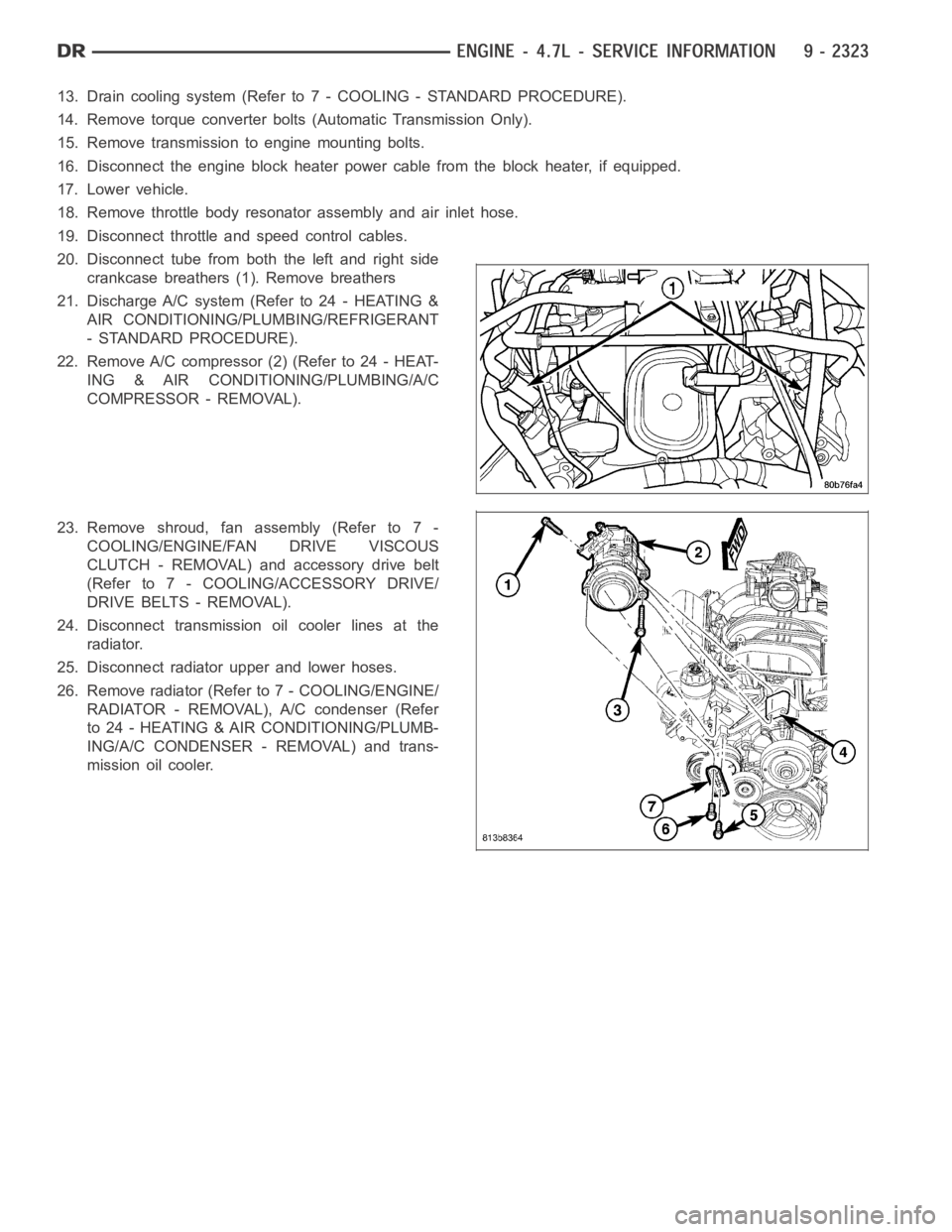
20. Disconnect tube from both the left and right side
crankcase breathers (1). Remove breathers
21. Discharge A/C system (Refer to 24 - HEATING &
AIR CONDITIONING/PLUMBING/REFRIGERANT
- STANDARD PROCEDURE).
22. Remove A/C compressor (2) (Refer to 24 - HEAT-
ING & AIR CONDITIONING/PLUMBING/A/C
COMPRESSOR - REMOVAL).
23. Remove shroud, fan assembly (Refer to 7 -
COOLING/ENGINE/FAN DRIVE VISCOUS
CLUTCH - REMOVAL) and accessory drive belt
(Refer to 7 - COOLING/ACCESSORY DRIVE/
DRIVE BELTS - REMOVAL).
24. Disconnect transmission oil cooler lines at the
radiator.
25. Disconnect radiator upper and lower hoses.
26. Remove radiator (Refer to 7 - COOLING/ENGINE/
RADIATOR - REMOVAL), A/C condenser (Refer
to 24 - HEATING & AIR CONDITIONING/PLUMB-
ING/A/C CONDENSER - REMOVAL) and trans-
mission oil cooler.
Page 1638 of 5267
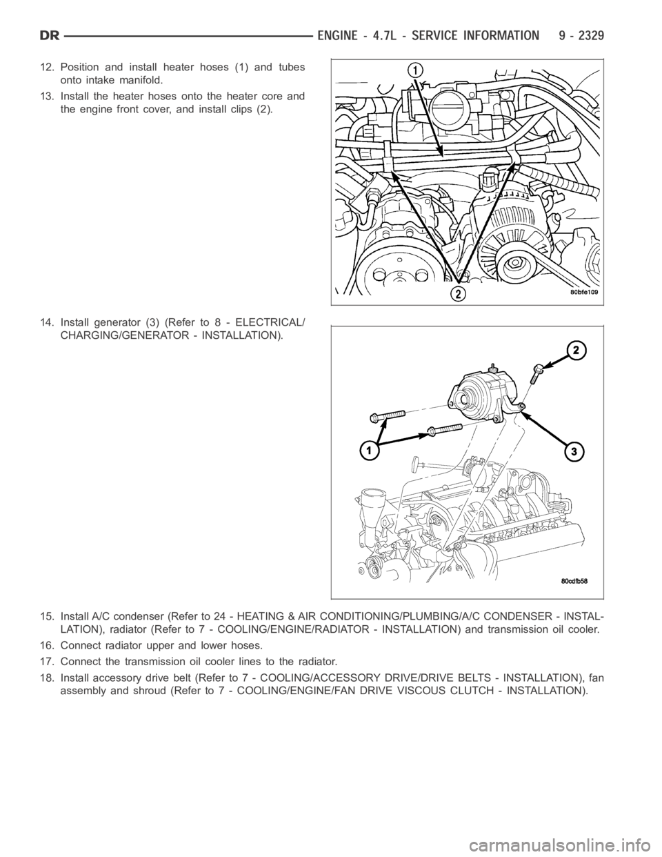
12. Position and install heater hoses (1) and tubes
onto intake manifold.
13. Install the heater hoses onto the heater core and
the engine front cover, and install clips (2).
14. Install generator (3) (Refer to 8 - ELECTRICAL/
CHARGING/GENERATOR - INSTALLATION).
15. Install A/C condenser (Refer to 24 - HEATING & AIR CONDITIONING/PLUMBING/A/C CONDENSER - INSTAL-
LATION), radiator (Refer to 7 - COOLING/ENGINE/RADIATOR - INSTALLATION)and transmission oil cooler.
16. Connect radiator upper and lower hoses.
17. Connect the transmission oil cooler lines to the radiator.
18. Install accessory drive belt (Refer to 7 - COOLING/ACCESSORY DRIVE/DRIVE BELTS - INSTALLATION), fan
assembly and shroud (Refer to 7 - COOLING/ENGINE/FAN DRIVE VISCOUS CLUTCH- INSTALLATION).
Page 1700 of 5267
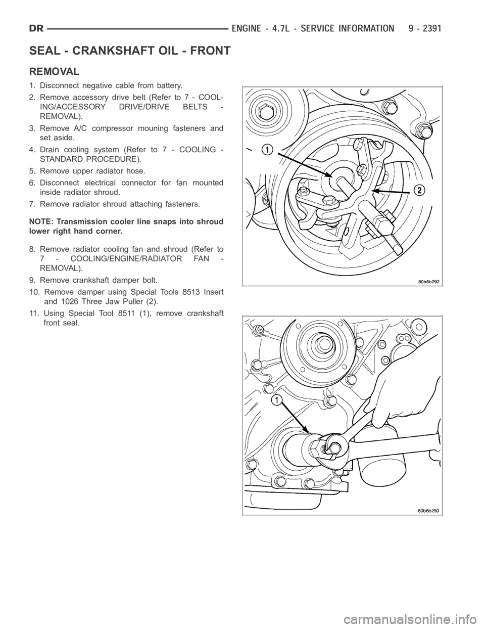
SEAL - CRANKSHAFT OIL - FRONT
REMOVAL
1. Disconnect negative cable from battery.
2. Remove accessory drive belt (Refer to 7 - COOL-
ING/ACCESSORY DRIVE/DRIVE BELTS -
REMOVAL).
3. Remove A/C compressor mouning fasteners and
set aside.
4. Drain cooling system (Refer to 7 - COOLING -
STANDARD PROCEDURE).
5. Remove upper radiator hose.
6. Disconnect electrical connector for fan mounted
inside radiator shroud.
7. Remove radiator shroud attaching fasteners.
NOTE: Transmission cooler line snaps into shroud
lower right hand corner.
8. Remove radiator cooling fan and shroud (Refer to
7 - COOLING/ENGINE/RADIATOR FAN -
REMOVAL).
9. Remove crankshaft damper bolt.
10. Remove damper using Special Tools 8513 Insert
and 1026 Three Jaw Puller (2).
11. Using Special Tool 8511 (1), remove crankshaft
front seal.
Page 1701 of 5267
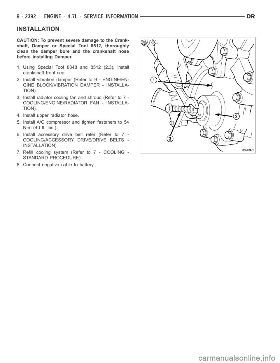
INSTALLATION
CAUTION: To prevent severe damage to the Crank-
shaft, Damper or Special Tool 8512, thoroughly
clean the damper bore and the crankshaft nose
before installing Damper.
1. Using Special Tool 8348 and 8512 (2,3), install
crankshaft front seal.
2. Install vibration damper (Refer to 9 - ENGINE/EN-
GINE BLOCK/VIBRATION DAMPER - INSTALLA-
TION).
3. Installradiatorcoolingfanandshroud(Referto7-
COOLING/ENGINE/RADIATOR FAN - INSTALLA-
TION).
4. Install upper radiator hose.
5. Install A/C compressor and tighten fasteners to 54
Nꞏm (40 ft. lbs.).
6. Install accessory drive belt refer (Refer to 7 -
COOLING/ACCESSORY DRIVE/DRIVE BELTS -
INSTALLATION).
7. Refill cooling system (Refer to 7 - COOLING -
STANDARD PROCEDURE).
8. Connect negative cable to battery.
Page 1712 of 5267
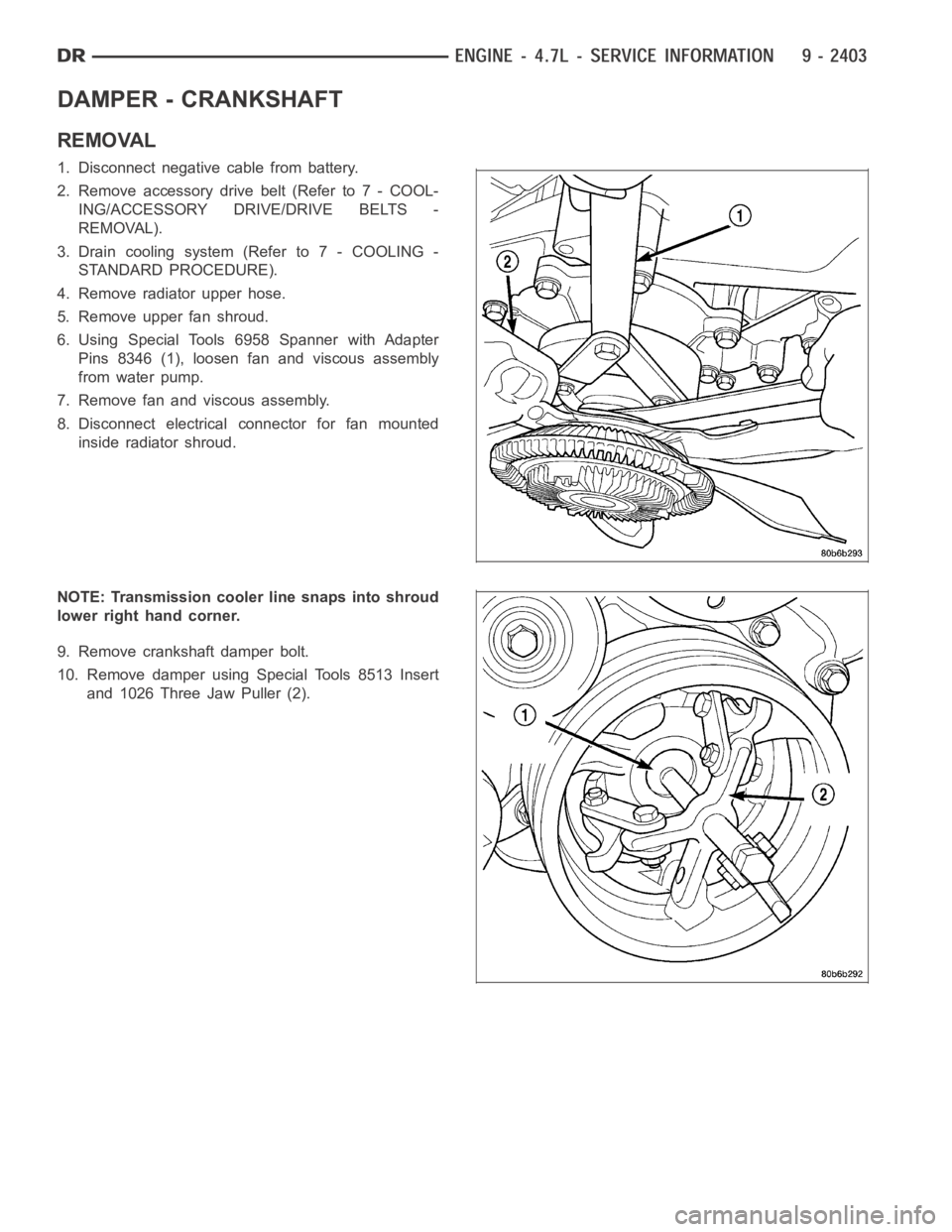
DAMPER - CRANKSHAFT
REMOVAL
1. Disconnect negative cable from battery.
2. Remove accessory drive belt (Refer to 7 - COOL-
ING/ACCESSORY DRIVE/DRIVE BELTS -
REMOVAL).
3. Drain cooling system (Refer to 7 - COOLING -
STANDARD PROCEDURE).
4. Remove radiator upper hose.
5. Remove upper fan shroud.
6. Using Special Tools 6958 Spanner with Adapter
Pins 8346 (1), loosen fan and viscous assembly
from water pump.
7. Remove fan and viscous assembly.
8. Disconnect electrical connector for fan mounted
inside radiator shroud.
NOTE: Transmission cooler line snaps into shroud
lower right hand corner.
9. Remove crankshaft damper bolt.
10. Remove damper using Special Tools 8513 Insert
and 1026 Three Jaw Puller (2).
Page 1713 of 5267
INSTALLATION
CAUTION: To prevent severe damage to the Crank-
shaft, Damper or Special Tool 8512–A, thoroughly
clean the damper bore and the crankshaft nose
before installing Damper.
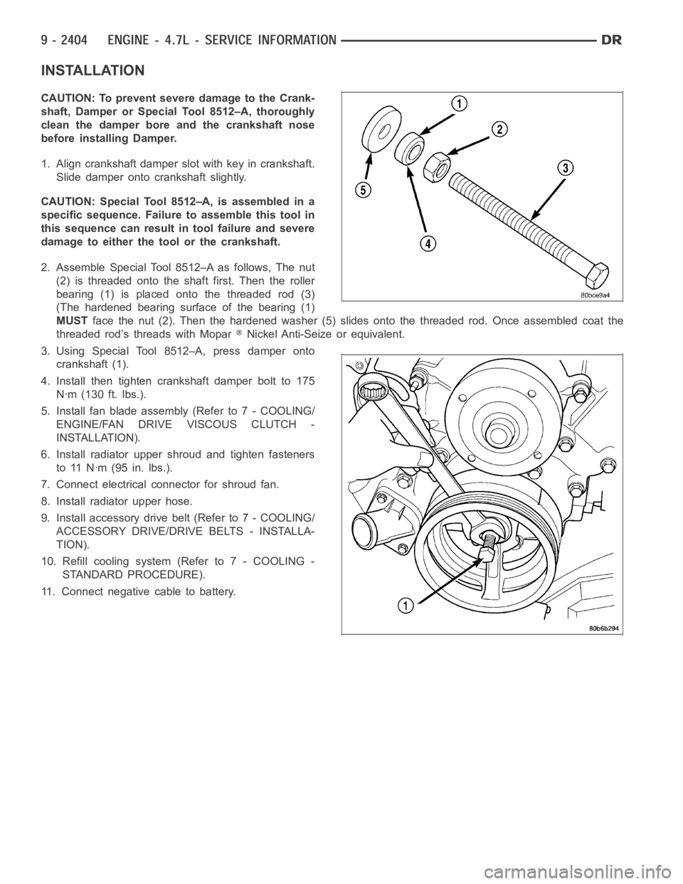
1. Align crankshaft damper slot with key in crankshaft.
Slide damper onto crankshaft slightly.
CAUTION: Special Tool 8512–A, is assembled in a
specific sequence. Failure to assemble this tool in
this sequence can result in tool failure and severe
damage to either the tool or the crankshaft.
2. Assemble Special Tool 8512–A as follows, The nut
(2) is threaded onto the shaft first. Then the roller
bearing (1) is placed onto the threaded rod (3)
(The hardened bearing surface of the bearing (1)
MUSTface the nut (2). Then the hardened washer (5) slides onto the threaded rod.Once assembled coat the
threaded rod’s threads with Mopar
Nickel Anti-Seize or equivalent.
3. Using Special Tool 8512–A, press damper onto
crankshaft (1).
4. Install then tighten crankshaft damper bolt to 175
Nꞏm (130 ft. lbs.).
5. Install fan blade assembly (Refer to 7 - COOLING/
ENGINE/FAN DRIVE VISCOUS CLUTCH -
INSTALLATION).
6. Install radiator upper shroud and tighten fasteners
to 11 Nꞏm (95 in. lbs.).
7. Connect electrical connector for shroud fan.
8. Install radiator upper hose.
9. Install accessory drive belt (Refer to 7 - COOLING/
ACCESSORY DRIVE/DRIVE BELTS - INSTALLA-
TION).
10. Refill cooling system (Refer to 7 - COOLING -
STANDARD PROCEDURE).
11. Connect negative cable to battery.
Page 1745 of 5267
COVER - TIMING
REMOVAL
1. Disconnect the battery negative cable.
2. Drain cooling system (Refer to 7 - COOLING -
STANDARD PROCEDURE).
3. Disconnect both heater hoses at timing cover.
4. Disconnect lower radiator hose at engine.
5. Remove crankshaft damper (Refer to 9 - ENGINE/
ENGINE BLOCK/VIBRATION DAMPER -
REMOVAL).
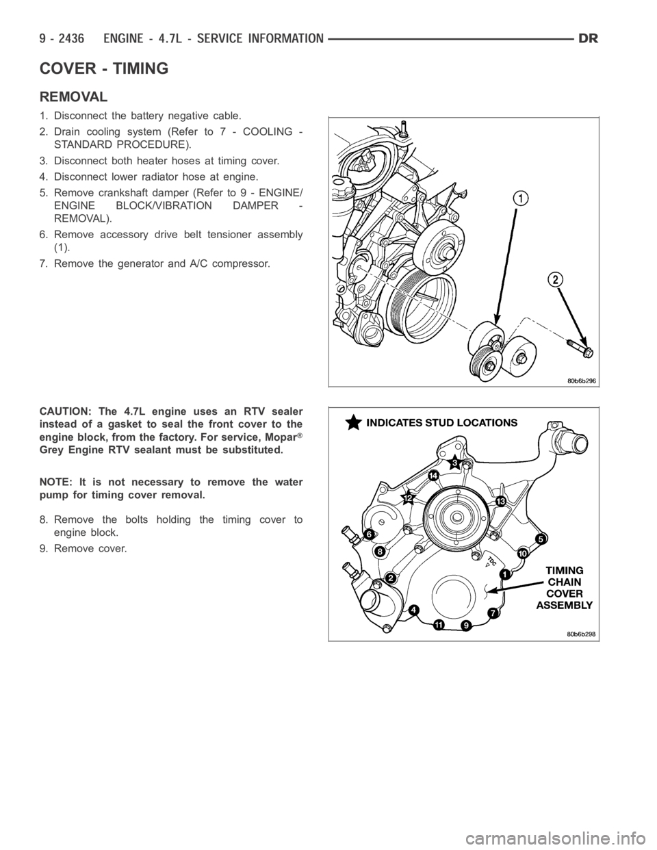
6. Remove accessory drive belt tensioner assembly
(1).
7. Remove the generator and A/C compressor.
CAUTION:The4.7LengineusesanRTVsealer
instead of a gasket to seal the front cover to the
engine block, from the factory. For service, Mopar
Grey Engine RTV sealant must be substituted.
NOTE: It is not necessary to remove the water
pump for timing cover removal.
8. Remove the bolts holding the timing cover to
engine block.
9. Remove cover.