DODGE RAM SRT-10 2006 Service Repair Manual
Manufacturer: DODGE, Model Year: 2006, Model line: RAM SRT-10, Model: DODGE RAM SRT-10 2006Pages: 5267, PDF Size: 68.7 MB
Page 3431 of 5267
In either case, air bubbles can cause overheating and/or fluid oxidation,and varnishing. This can interfere with nor-
mal valve, clutch, and accumulator operation. Foaming can also result in fluid escaping from the transmission vent
where it may be mistaken for a leak.
After the fluid has been checked, seat the dipstick fully to seal out water and dirt.
The transmission has a dipstick to check oil level. It is located on the right side of the engine. Be sure to wipe all
dirt from dipstick handle before removing.
The torque converter fills in both the P(PARK) and N (NEUTRAL) positions. Place the selector lever in P (PARK)
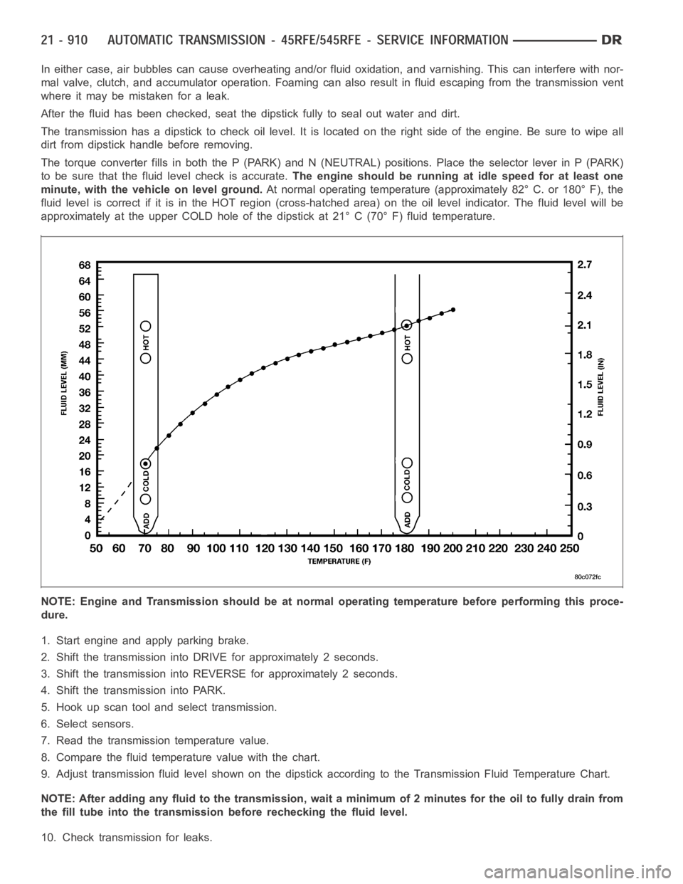
to be sure that the fluid level check is accurate.The engine should be running at idle speed for at least one
minute, with the vehicle on level ground.At normal operating temperature (approximately 82° C. or 180° F), the
fluid level is correct if it is in the HOT region (cross-hatched area) on theoil level indicator. The fluid level will be
approximately at the upper COLD hole of the dipstick at 21° C (70° F) fluid temperature.
NOTE: Engine and Transmission should be at normal operating temperature before performing this proce-
dure.
1. Start engine and apply parking brake.
2. Shift the transmission into DRIVE for approximately 2 seconds.
3. Shift the transmission into REVERSE for approximately 2 seconds.
4. Shift the transmission into PARK.
5. Hook up scan tool andselect transmission.
6. Select sensors.
7. Read the transmission temperature value.
8. Compare the fluid temperature value with the chart.
9. Adjust transmission fluid level shown on the dipstick according to the Transmission Fluid Temperature Chart.
NOTE: After adding any fluid to the transmission, wait a minimum of 2 minutes for the oil to fully drain from
the fill tube into the transmission before rechecking the fluid level.
10. Check transmission for leaks.
Page 3432 of 5267
FLUID AND FILTER REPLACEMENT
For proper service intervals (Refer to LUBRICATION & MAINTENANCE/MAINTENANCE SCHEDULES - DESCRIP-
TION).
REMOVAL
1. Hoist and support vehicle on safety stands.
2. Place a large diameter shallow drain pan beneath the transmission pan.
3. Remove bolts holding front and sides of pan to transmission.
4. Loosen bolts holding rear of pan to transmission.
5. Slowly separate front of pan away from transmission allowing the fluid to drain into drain pan.
6. Hold up pan and remove remaining bolts holding pan to transmission.
7. While holding pan level, lower pan away from transmission.
8. Pour remaining fluid in pan into drain pan.
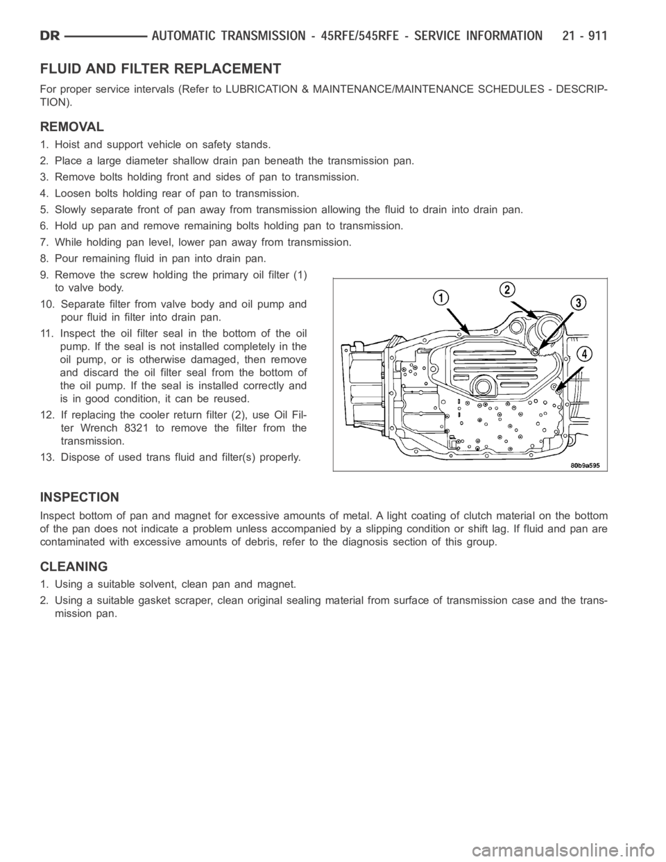
9. Remove the screw holding the primary oil filter (1)
to valve body.
10. Separate filter from valve body and oil pump and
pour fluid in filter into drain pan.
11. Inspect the oil filter seal in the bottom of the oil
pump. If the seal is not installed completely in the
oil pump, or is otherwise damaged, then remove
and discard the oil filter seal from the bottom of
the oil pump. If the seal is installed correctly and
is in good condition, it can be reused.
12. If replacing the cooler return filter (2), use Oil Fil-
ter Wrench 8321 to remove the filter from the
transmission.
13. Dispose of used trans fluid and filter(s) properly.
INSPECTION
Inspect bottom of pan and magnet for excessive amounts of metal. A light coating of clutch material on the bottom
of the pan does not indicate a problem unless accompanied by a slipping condition or shift lag. If fluid and pan are
contaminated with excessive amounts of debris, refer to the diagnosis section of this group.
CLEANING
1. Using a suitable solvent, clean pan and magnet.
2. Using a suitable gasket scraper, clean original sealing material from surface of transmission case and the trans-
mission pan.
Page 3433 of 5267
INSTALLATION
CAUTION: The primary oil filter seal MUST be fully
installed flush against the oil pump body. DO NOT
install the seal onto the filter neck and attempt to
install the filter and seal as an assembly. Damage
to the transmission will result.
1. If necessary, install a new primary oil filter seal in
the oil pump inlet bore. Seat the seal in the bore
with a suitable tool (appropriately sized drift or
socket, the butt end of a hammer, or other suitable
tool).
2. Place replacement filter in position on valve body
and into the oil pump.
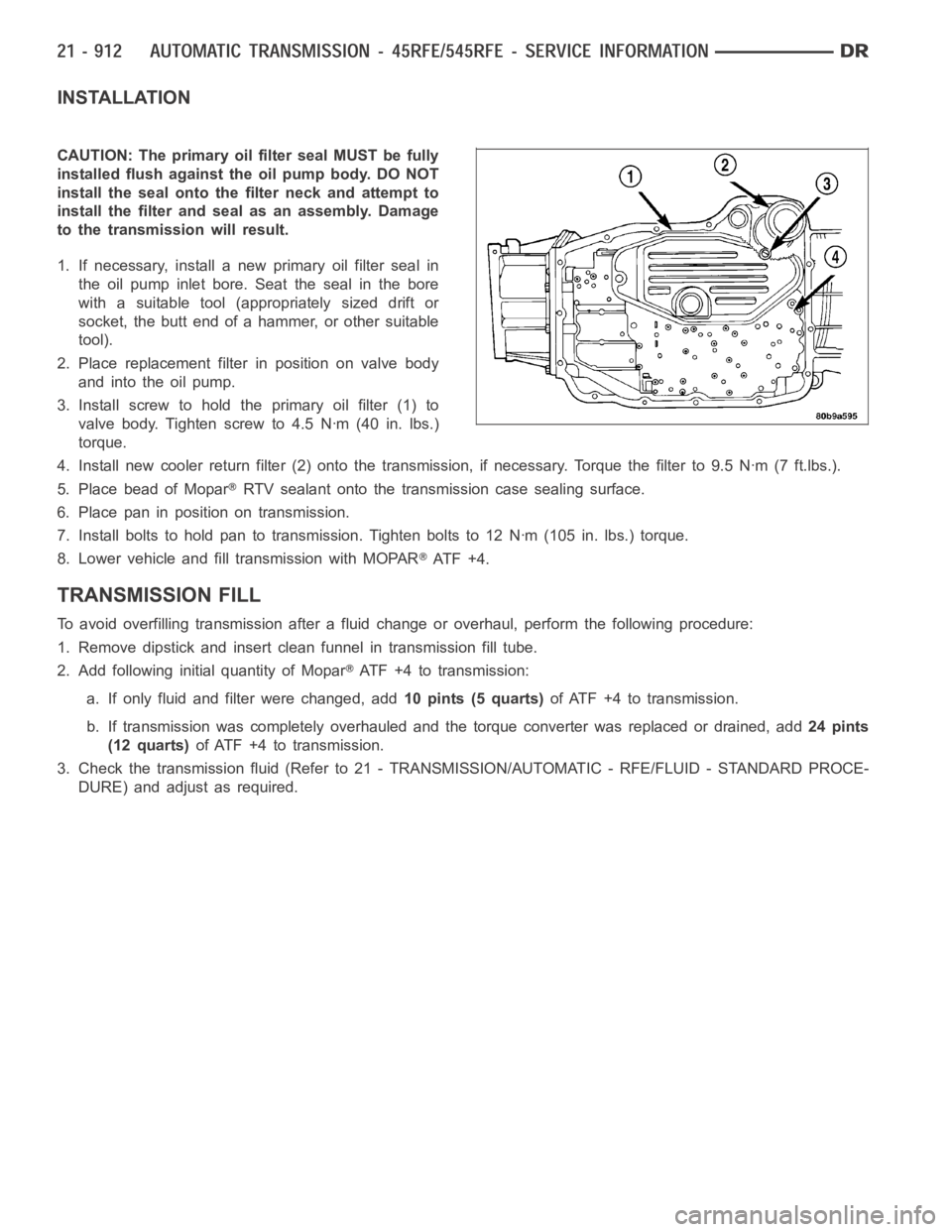
3. Install screw to hold the primary oil filter (1) to
valve body. Tighten screw to 4.5 Nꞏm (40 in. lbs.)
torque.
4. Install new cooler return filter (2) onto the transmission, if necessary. Torque the filter to 9.5 Nꞏm (7 ft.lbs.).
5. Place bead of Mopar
RTV sealant onto the transmission case sealing surface.
6. Place pan in position on transmission.
7. Install bolts to hold pan to transmission. Tighten bolts to 12 Nꞏm (105 in. lbs.) torque.
8. Lower vehicle and fill transmission with MOPAR
AT F + 4 .
TRANSMISSION FILL
To avoid overfilling transmission after a fluid change or overhaul, perform the following procedure:
1. Remove dipstick and insert clean funnel in transmission fill tube.
2. Add following initial quantity of Mopar
ATF+4totransmission:
a. If only fluid and filter were changed, add10 pints (5 quarts)of ATF +4 to transmission.
b. If transmission was completely overhauled and the torque converter wasreplaced or drained, add24 pints
(12 quarts)ofATF+4totransmission.
3. Check the transmission fluid (Refer to 21 - TRANSMISSION/AUTOMATIC - RFE/FLUID - STANDARD PROCE-
DURE) and adjust as required.
Page 3434 of 5267
CABLE-GEARSHIFT
DIAGNOSIS AND TESTING - GEARSHIFT CABLE
1. Engine starts must be possible with shift lever in PARK or NEUTRAL positions only. Engine starts must not be
possible in any other gear position.
2. With the shift lever in the:
a. PARK position - Apply upward force on the shift arm and remove pressure. Engine starts must be possible.
b. PARK position - Apply downward force on the shift arm and remove pressure. Engine starts must be pos-
sible.
c. NEUTRAL position - Normal position. Engine starts must be possible.
d. NEUTRAL position - Engine running and brakes applied, apply upward forceontheshiftarm.Transmission
shall not be able to shift from neutral to reverse.
REMOVAL
1. Shift transmission into PARK.
2. Raise vehicle.
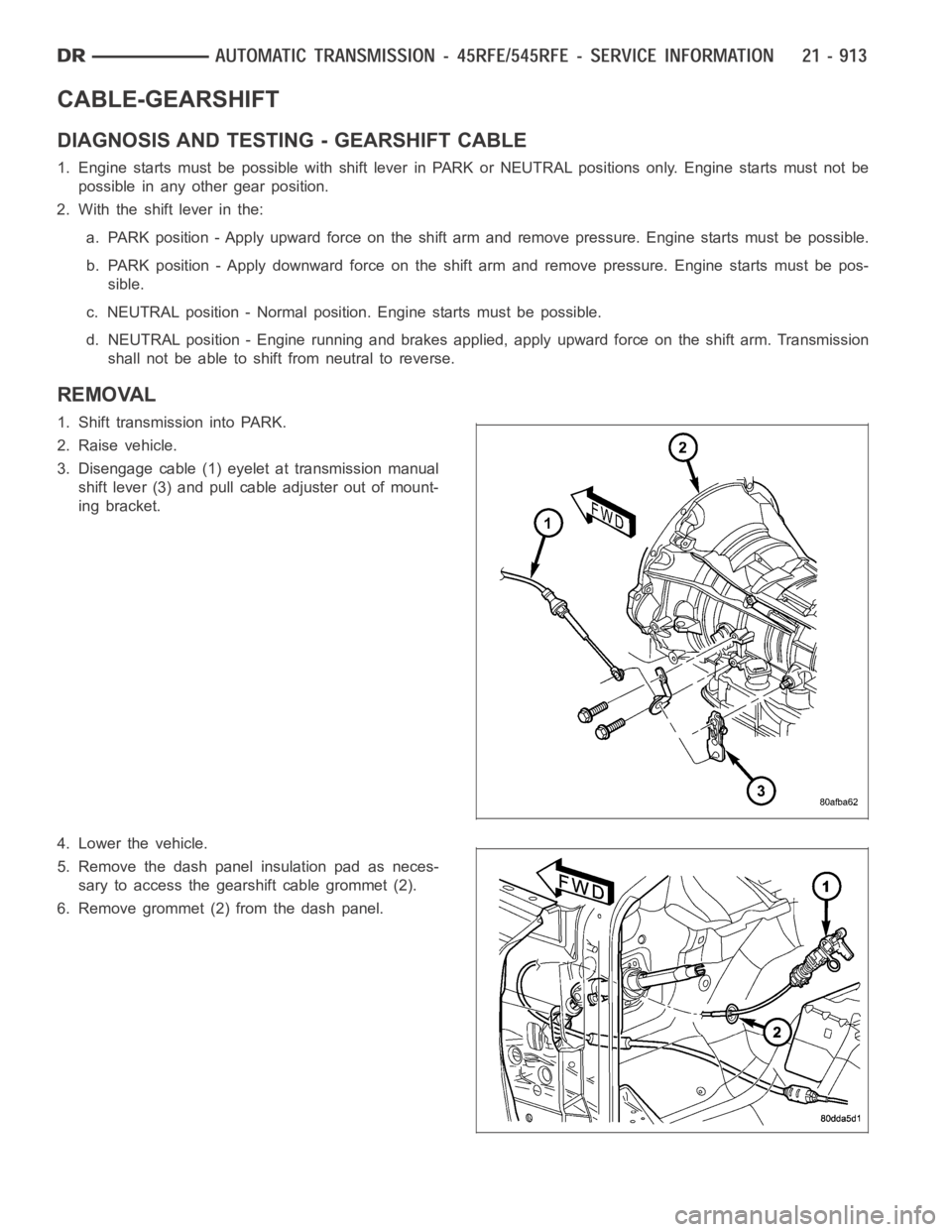
3. Disengage cable (1) eyelet at transmission manual
shift lever (3) and pull cable adjuster out of mount-
ing bracket.
4. Lower the vehicle.
5. Remove the dash panel insulation pad as neces-
sary to access the gearshift cable grommet (2).
6. Remove grommet (2) from the dash panel.
Page 3435 of 5267
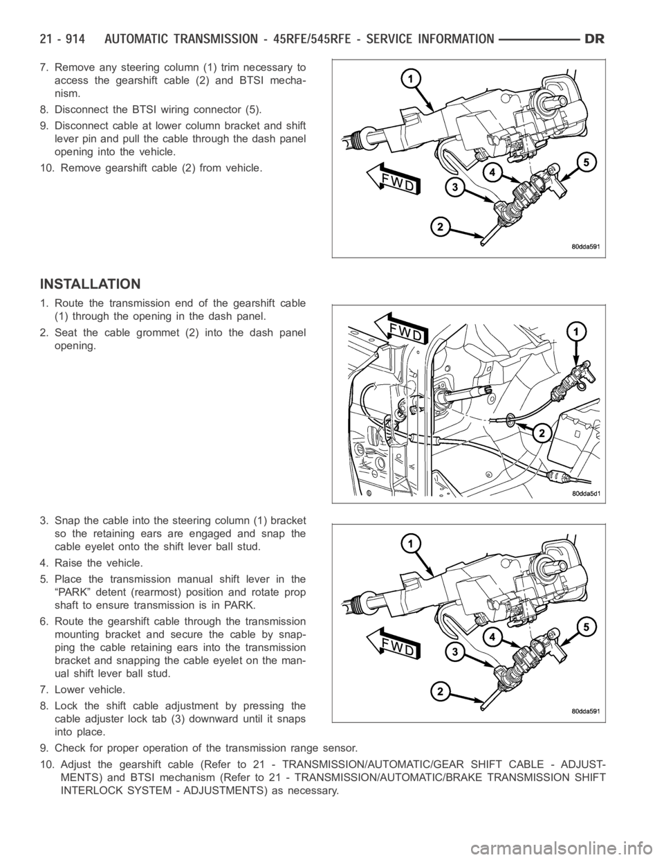
7. Remove any steering column (1) trim necessary to
access the gearshift cable (2) and BTSI mecha-
nism.
8. Disconnect the BTSI wiring connector (5).
9. Disconnect cable at lower column bracket and shift
lever pin and pull the cable through the dash panel
opening into the vehicle.
10. Remove gearshift cable (2) from vehicle.
INSTALLATION
1. Route the transmission end of the gearshift cable
(1) through the opening in the dash panel.
2. Seat the cable grommet (2) into the dash panel
opening.
3. Snap the cable into the steering column (1) bracket
so the retaining ears are engaged and snap the
cable eyelet onto the shift lever ball stud.
4. Raise the vehicle.
5. Place the transmission manual shift lever in the
“PARK” detent (rearmost) position and rotate prop
shaft to ensure transmission is in PARK.
6. Route the gearshift cable through the transmission
mounting bracket and secure the cable by snap-
ping the cable retaining ears into the transmission
bracket and snapping the cable eyelet on the man-
ual shift lever ball stud.
7. Lower vehicle.
8. Lock the shift cable adjustment by pressing the
cable adjuster lock tab (3) downward until it snaps
into place.
9. Check for proper operation of the transmission range sensor.
10. Adjust the gearshift cable (Refer to 21 - TRANSMISSION/AUTOMATIC/GEAR SHIFT CABLE - ADJUST-
MENTS) and BTSI mechanism (Refer to 21 - TRANSMISSION/AUTOMATIC/BRAKE TRANSMISSION SHIFT
INTERLOCK SYSTEM - ADJUSTMENTS) as necessary.
Page 3436 of 5267
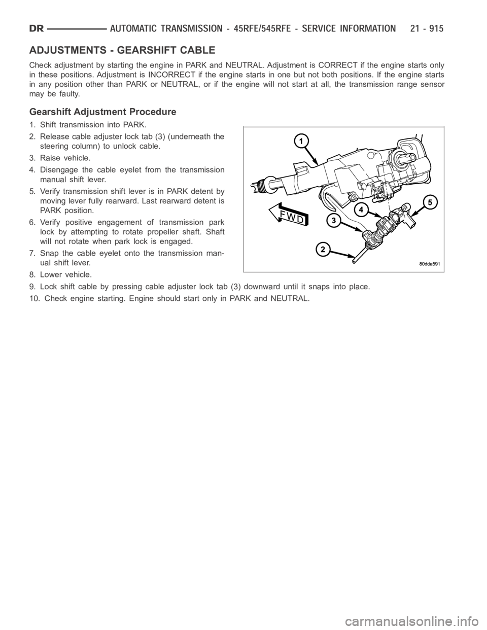
ADJUSTMENTS - GEARSHIFT CABLE
Check adjustment by starting the engine in PARK and NEUTRAL. Adjustment isCORRECT if the engine starts only
in these positions. Adjustment is INCORRECT if the engine starts in one butnot both positions. If the engine starts
in any position other than PARK or NEUTRAL, or if the engine will not start atall, the transmission range sensor
may be faulty.
Gearshift Adjustment Procedure
1. Shift transmission into PARK.
2. Release cable adjuster lock tab (3) (underneath the
steering column) to unlock cable.
3. Raise vehicle.
4. Disengage the cable eyelet from the transmission
manual shift lever.
5. Verify transmission shift lever is in PARK detent by
moving lever fully rearward. Last rearward detent is
PARK position.
6. Verify positive engagement of transmission park
lock by attempting to rotate propeller shaft. Shaft
will not rotate when park lock is engaged.
7. Snap the cable eyelet onto the transmission man-
ual shift lever.
8. Lower vehicle.
9. Lock shift cable by pressing cable adjuster lock tab (3) downward until it snaps into place.
10. Check engine starting. Engine should start only in PARK and NEUTRAL.
Page 3437 of 5267
CLUTCHES-HOLDING
DESCRIPTION
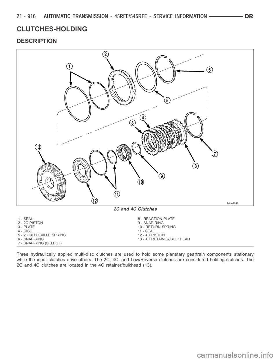
Three hydraulically applied multi-disc clutches are used to hold some planetary geartrain components stationary
while the input clutches drive others. The 2C, 4C, and Low/Reverse clutches are considered holding clutches. The
2C and 4C clutches are located in the 4C retainer/bulkhead (13).
2C and 4C Clutches
1 - SEAL 8 - REACTION PLATE
2-2CPISTON 9-SNAP-RING
3 - PLATE 10 - RETURN SPRING
4 - DISC 11 - SEAL
5 - 2C BELLEVILLE SPRING 12 - 4C PISTON
6 - SNAP-RING 13 - 4C RETAINER/BULKHEAD
7 - SNAP-RING (SELECT)
Page 3438 of 5267
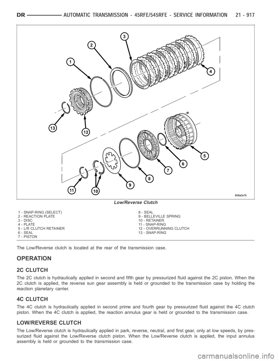
The Low/Reverse clutch is located at the rear of the transmission case.
OPERATION
2C CLUTCH
The 2C clutch is hydraulically applied in second and fifth gear by pressurized fluid against the 2C piston. When the
2C clutch is applied, the reverse sun gear assembly is held or grounded to the transmission case by holding the
reaction planetary carrier.
4C CLUTCH
The 4C clutch is hydraulically applied in second prime and fourth gear by pressurized fluid against the 4C clutch
piston. When the 4C clutch is applied, the reaction annulus gear is held or grounded to the transmission case.
LOW/REVERSE CLUTCH
The Low/Reverse clutch is hydraulically applied in park, reverse, neutral, and first gear, only at low speeds, by pres-
surized fluid against the Low/Reverse clutch piston. When the Low/Reverse clutch is applied, the input annulus
assembly is held or grounded to the transmission case.
Low/Reverse Clutch
1 - SNAP-RING (SELECT) 8 - SEAL
2 - REACTION PLATE 9 - BELLEVILLE SPRING
3 - DISC 10 - RETAINER
4 - PLATE 11 - SNAP-RING
5 - L/R CLUTCH RETAINER 12 - OVERRUNNING CLUTCH
6 - SEAL 13 - SNAP-RING
7-PISTON
Page 3439 of 5267
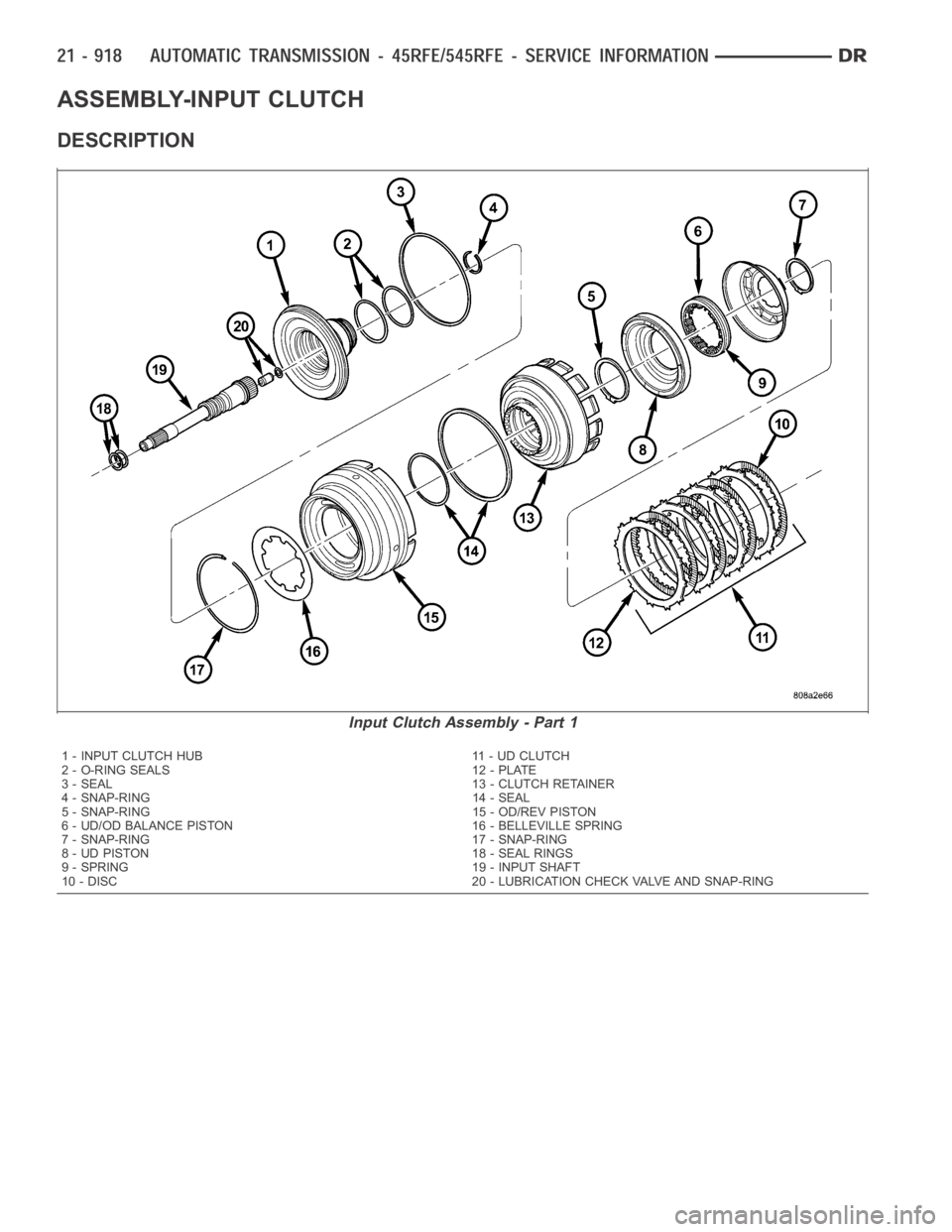
ASSEMBLY-INPUT CLUTCH
DESCRIPTION
Input Clutch Assembly - Part 1
1 - INPUT CLUTCH HUB 11 - UD CLUTCH
2 - O-RING SEALS 12 - PLATE
3 - SEAL 13 - CLUTCH RETAINER
4 - SNAP-RING 14 - SEAL
5 - SNAP-RING 15 - OD/REV PISTON
6 - UD/OD BALANCE PISTON 16 - BELLEVILLE SPRING
7 - SNAP-RING 17 - SNAP-RING
8 - UD PISTON 18 - SEAL RINGS
9 - SPRING 19 - INPUT SHAFT
10 - DISC 20 - LUBRICATION CHECK VALVE AND SNAP-RING
Page 3440 of 5267
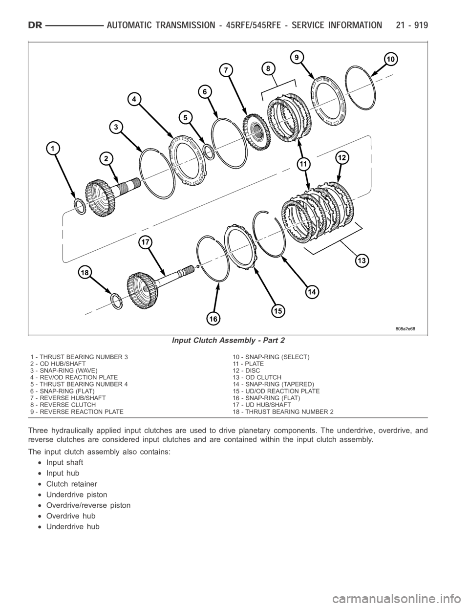
Three hydraulically applied input clutches are used to drive planetary components. The underdrive, overdrive, and
reverse clutches are considered input clutches and are contained within the input clutch assembly.
The input clutch assembly also contains:
Input shaft
Input hub
Clutch retainer
Underdrive piston
Overdrive/reverse piston
Overdrive hub
Underdrive hub
Input Clutch Assembly - Part 2
1 - THRUST BEARING NUMBER 3 10 - SNAP-RING (SELECT)
2 - OD HUB/SHAFT 11 - PLATE
3 - SNAP-RING (WAVE) 12 - DISC
4 - REV/OD REACTION PLATE 13 - OD CLUTCH
5 - THRUST BEARING NUMBER 4 14 - SNAP-RING (TAPERED)
6 - SNAP-RING (FLAT) 15 - UD/OD REACTION PLATE
7 - REVERSE HUB/SHAFT 16 - SNAP-RING (FLAT)
8 - REVERSE CLUTCH 17 - UD HUB/SHAFT
9 - REVERSE REACTION PLATE 18 - THRUST BEARING NUMBER 2