DODGE RAM SRT-10 2006 Service Repair Manual
Manufacturer: DODGE, Model Year: 2006, Model line: RAM SRT-10, Model: DODGE RAM SRT-10 2006Pages: 5267, PDF Size: 68.7 MB
Page 3471 of 5267
SEAL-OIL PUMP FRONT
REMOVAL
1. Remove transmission from the vehicle.
2. Remove the torque converter from the transmission.
3. Usingascrewmountedinaslidehammer,removetheoilpumpfrontseal.
INSTALLATION
1. Clean seal bore of the oil pump of any residue or
particles from the original seal.
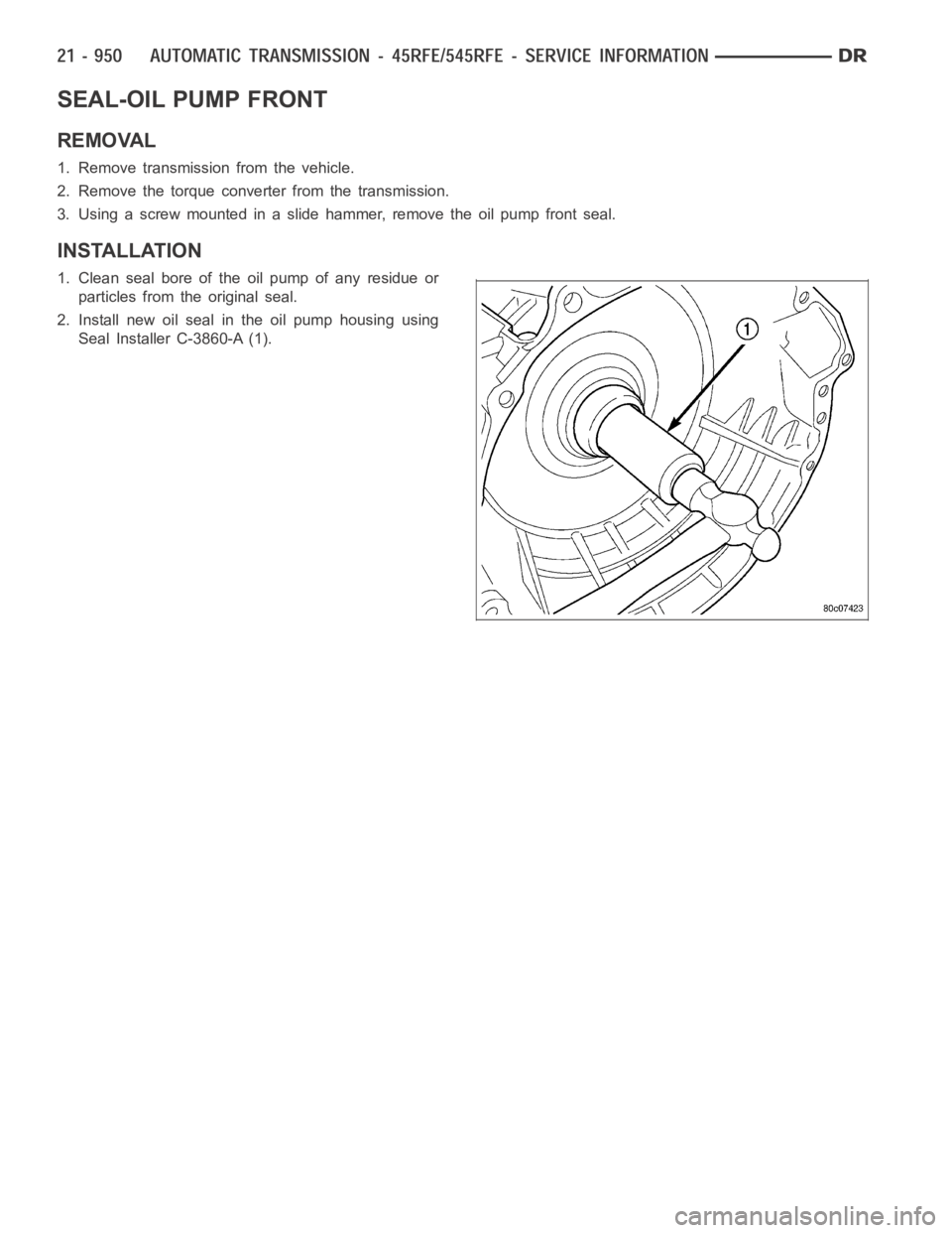
2. Install new oil seal in the oil pump housing using
Seal Installer C-3860-A (1).
Page 3472 of 5267
SENSOR-OUTPUT SPEED
DESCRIPTION
The Input and Output Speed Sensors are two-wire magnetic pickup devices that generate AC signals as rotation
occurs. They are mounted in the left side of the transmission case and are considered primary inputs to the Trans-
mission Control Module (TCM).
OPERATION
The Input Speed Sensor provides information on how fast the input shaft is rotating. As the teeth of the input clutch
hub pass by the sensor coil, an AC voltage is generated and sent to the TCM. The TCM interprets this information
as input shaft rpm.
The Output Speed Sensor generates an AC signal in a similar fashion, thoughitscoilisexcitedbyrotationofthe
rear planetary carrier lugs. The TCM interprets this information as outputshaftrpm.
The TCM compares the input and output speed signals to determine the following:
Transmission gear ratio
Speed ratio error detection
CVI calculation
The TCM also compares the input speed signal and the engine speed signal to determine the following:
Torque converter clutch slippage
Torque converter element speed ratio
REMOVAL
1. Raise vehicle.
2. Place a suitable fluid catch pan under the transmis-
sion.
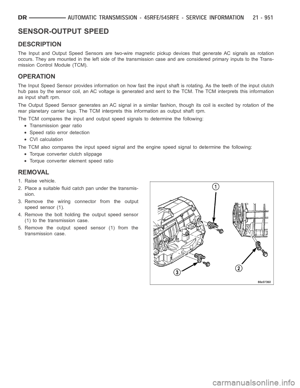
3. Remove the wiring connector from the output
speed sensor (1).
4. Remove the bolt holding the output speed sensor
(1) to the transmission case.
5. Remove the output speed sensor (1) from the
transmission case.
Page 3473 of 5267
INSTALLATION
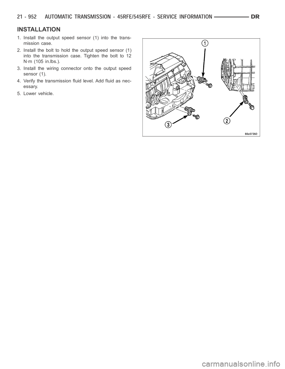
1. Install the output speed sensor (1) into the trans-
mission case.
2. Install the bolt to hold the output speed sensor (1)
into the transmission case. Tighten the bolt to 12
Nꞏm (105 in.lbs.).
3. Install the wiring connector onto the output speed
sensor (1).
4. Verify the transmission fluid level. Add fluid as nec-
essary.
5. Lower vehicle.
Page 3474 of 5267
SWITCH-TOW/HAUL OVERDRIVE
DESCRIPTION
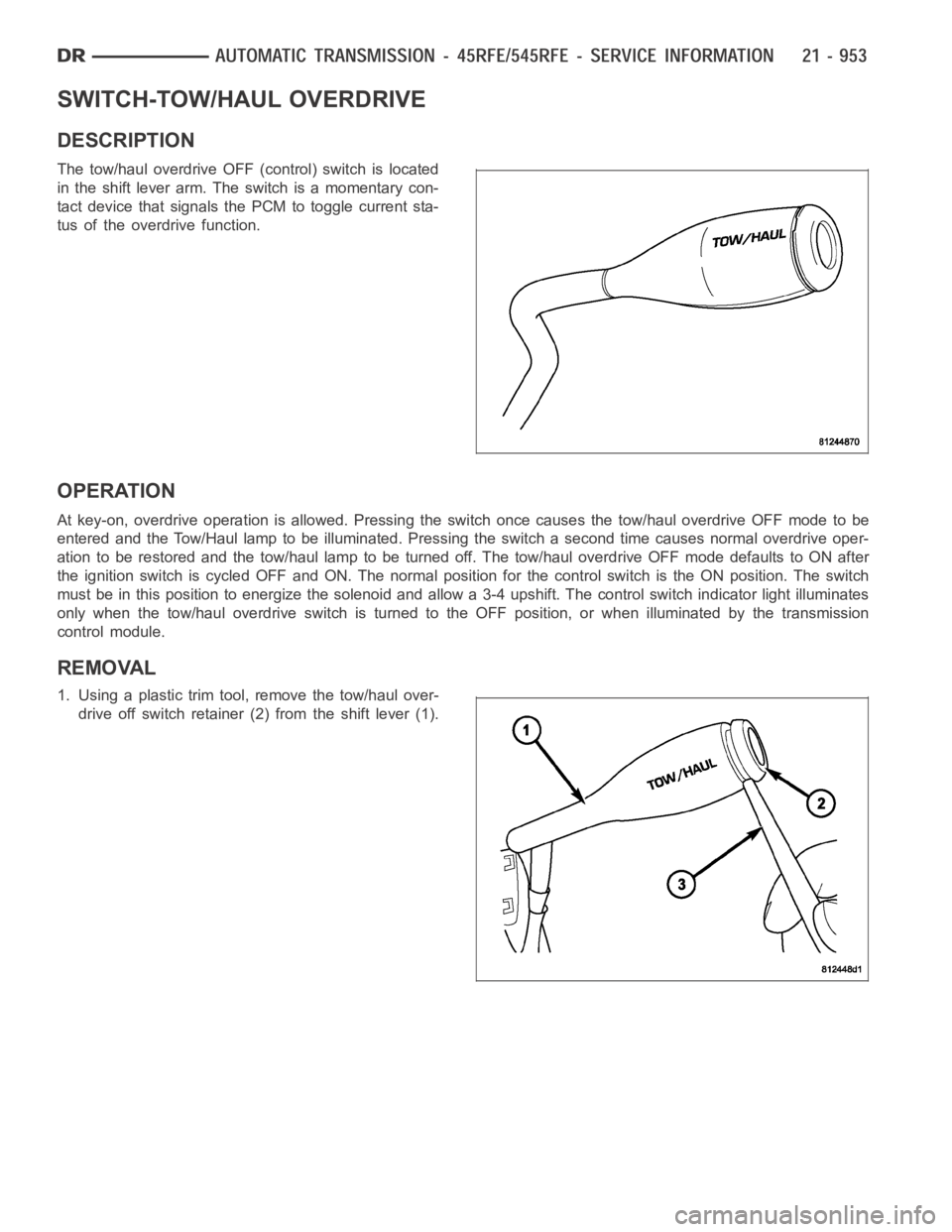
The tow/haul overdrive OFF (control) switch is located
in the shift lever arm. The switch is a momentary con-
tact device that signals the PCM to toggle current sta-
tus of the overdrive function.
OPERATION
At key-on, overdrive operation is allowed. Pressing the switch once causes the tow/haul overdrive OFF mode to be
entered and the Tow/Haul lamp to be illuminated. Pressing the switch a second time causes normal overdrive oper-
ationtoberestoredandthetow/haullamptobeturnedoff.Thetow/hauloverdrive OFF mode defaults to ON after
the ignition switch is cycled OFF and ON. The normal position for the control switch is the ON position. The switch
must be in this position to energize the solenoid and allow a 3-4 upshift. The control switch indicator light illuminates
only when the tow/haul overdrive switch is turned to the OFF position, or when illuminated by the transmission
control module.
REMOVAL
1. Using a plastic trim tool, remove the tow/haul over-
drive off switch retainer (2) from the shift lever (1).
Page 3475 of 5267
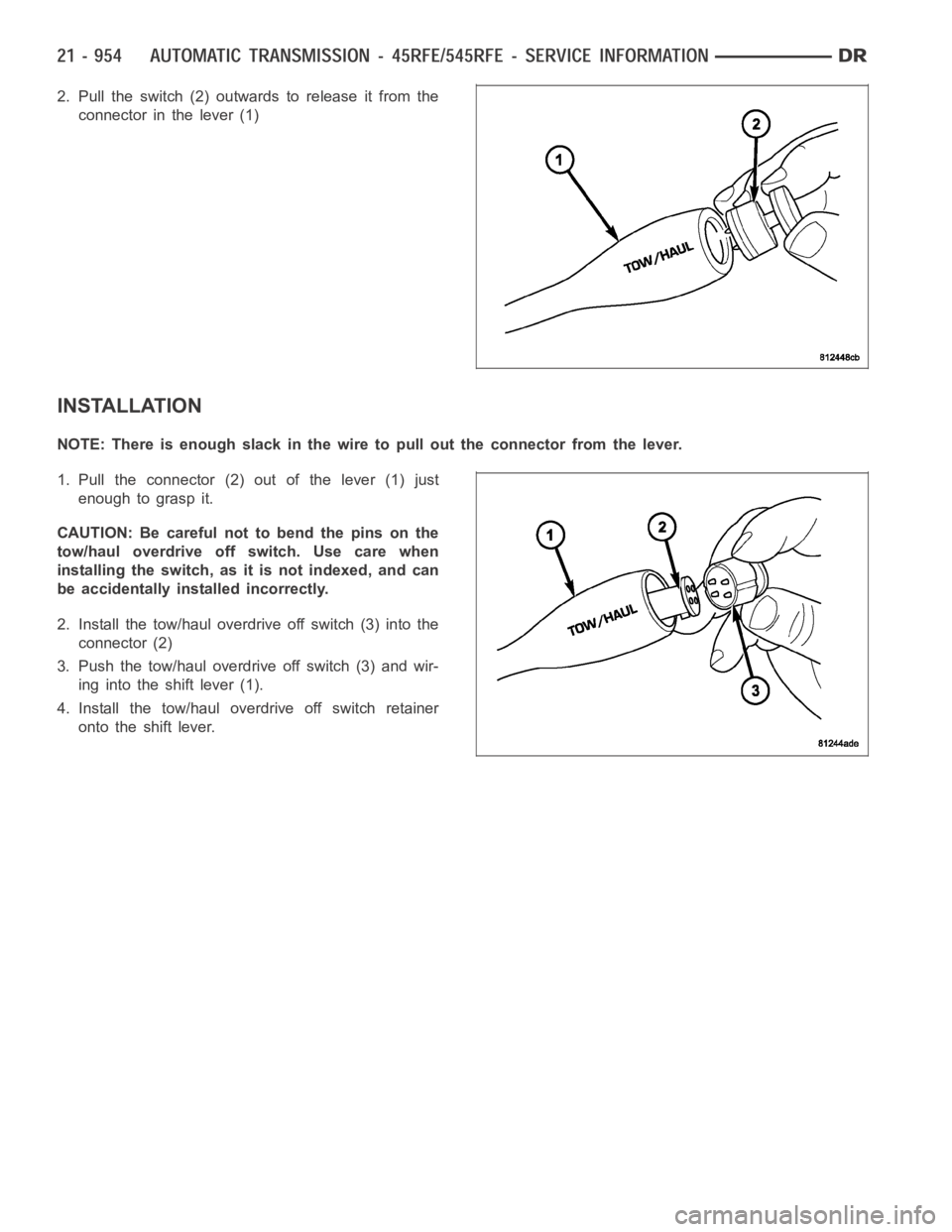
2. Pull the switch (2) outwards to release it from the
connector in the lever (1)
INSTALLATION
NOTE: There is enough slack in the wire to pull out the connector from the lever.
1. Pull the connector (2) out of the lever (1) just
enough to grasp it.
CAUTION: Be careful not to bend the pins on the
tow/haul overdrive off switch. Use care when
installing the switch, as it is not indexed, and can
be accidentally installed incorrectly.
2. Install the tow/haul overdrive off switch (3) into the
connector (2)
3. Push the tow/haul overdrive off switch (3) and wir-
ing into the shift lever (1).
4. Install the tow/haul overdrive off switch retainer
onto the shift lever.
Page 3476 of 5267
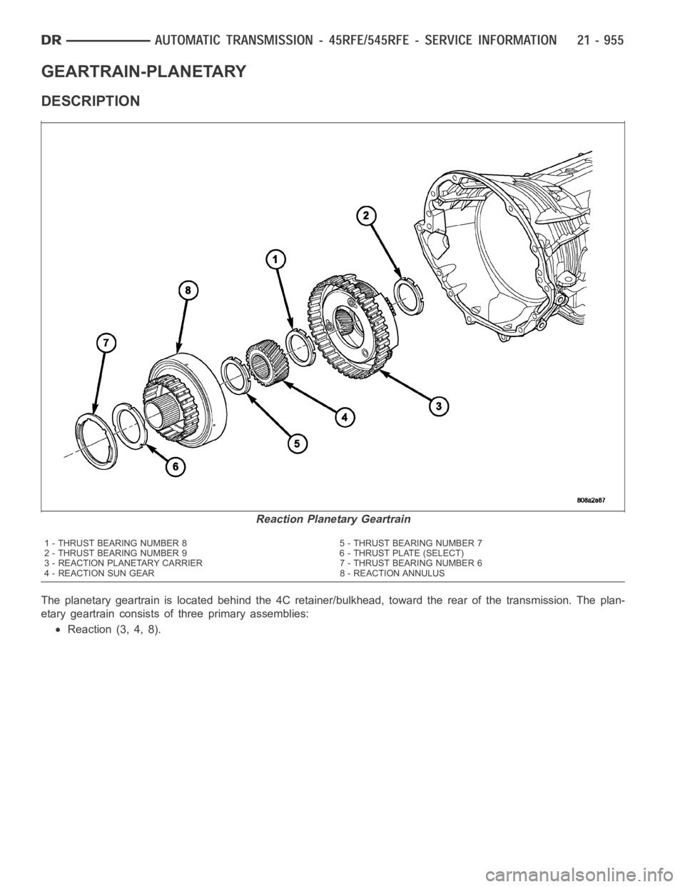
GEARTRAIN-PLANETARY
DESCRIPTION
The planetary geartrain is located behind the 4C retainer/bulkhead, toward the rear of the transmission. The plan-
etary geartrain consists of three primary assemblies:
Reaction (3, 4, 8).
Reaction Planetary Geartrain
1 - THRUST BEARING NUMBER 8 5 - THRUST BEARING NUMBER 7
2 - THRUST BEARING NUMBER 9 6 - THRUST PLATE (SELECT)
3 - REACTION PLANETARY CARRIER 7 - THRUST BEARING NUMBER 6
4 - REACTION SUN GEAR 8 - REACTION ANNULUS
Page 3477 of 5267
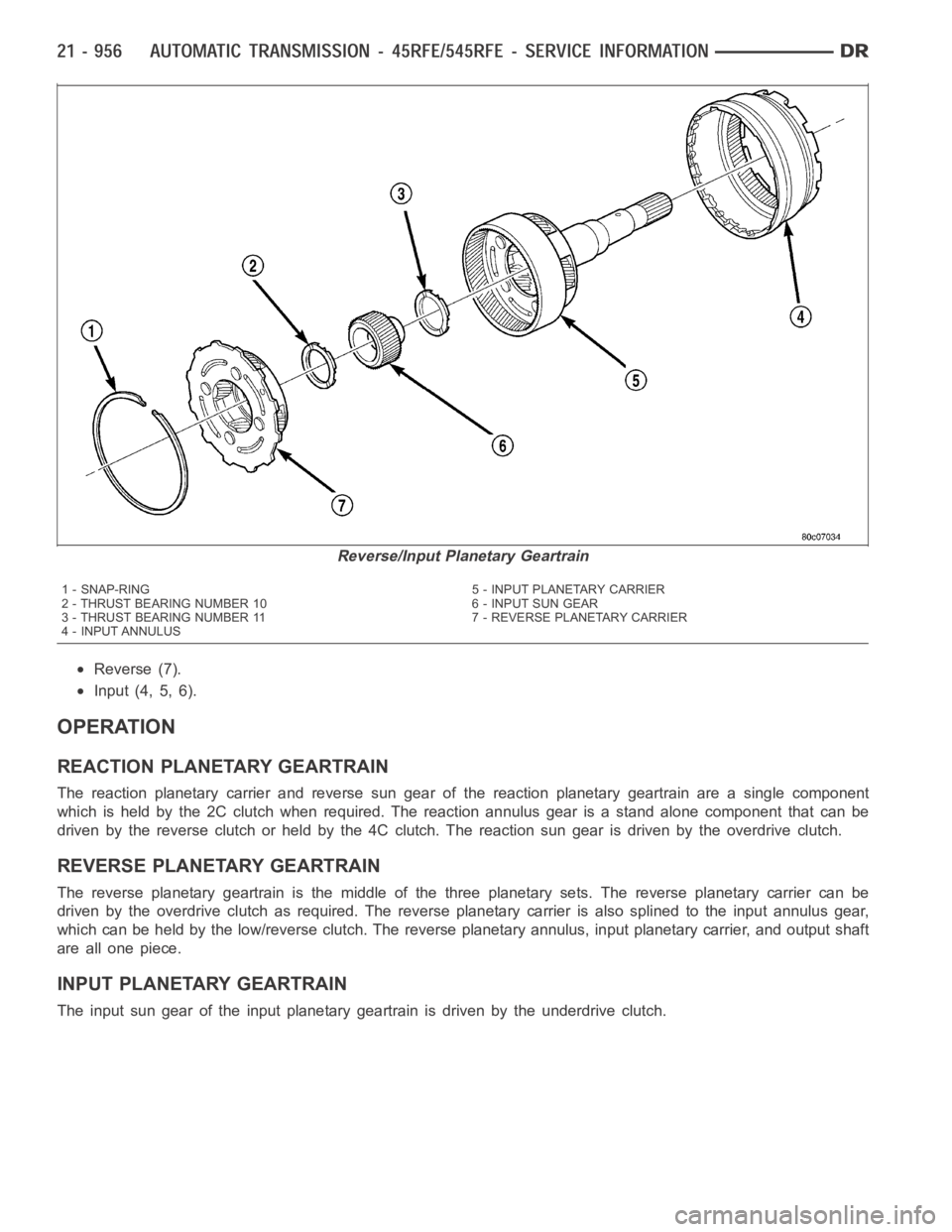
Reverse (7).
Input (4, 5, 6).
OPERATION
REACTION PLANETARY GEARTRAIN
The reaction planetary carrier and reverse sun gear of the reaction planetary geartrain are a single component
which is held by the 2C clutch when required. The reaction annulus gear is a stand alone component that can be
driven by the reverse clutch or held by the 4C clutch. The reaction sun gear is driven by the overdrive clutch.
REVERSE PLANETARY GEARTRAIN
The reverse planetary geartrain is the middle of the three planetary sets.The reverse planetary carrier can be
driven by the overdrive clutch as required. The reverse planetary carrieris also splined to the input annulus gear,
which can be held by the low/reverse clutch. The reverse planetary annulus, input planetary carrier, and output shaft
areallonepiece.
INPUT PLANETARY GEARTRAIN
The input sun gear of the input planetary geartrain is driven by the underdrive clutch.
Reverse/Input Planetary Geartrain
1 - SNAP-RING 5 - INPUT PLANETARY CARRIER
2 - THRUST BEARING NUMBER 10 6 - INPUT SUN GEAR
3 - THRUST BEARING NUMBER 11 7 - REVERSE PLANETARY CARRIER
4 - INPUT ANNULUS
Page 3478 of 5267
DISASSEMBLY
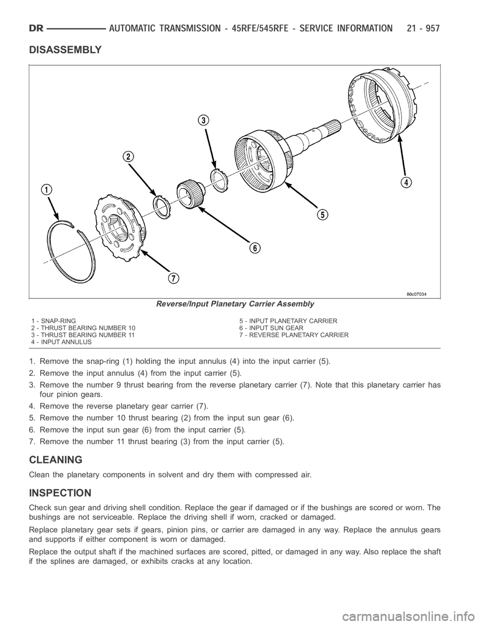
1. Remove the snap-ring (1) holding the input annulus (4) into the input carrier (5).
2. Remove the input annulus (4) from the input carrier (5).
3. Remove the number 9 thrust bearing from the reverse planetary carrier (7). Note that this planetary carrier has
four pinion gears.
4. Remove the reverse planetary gear carrier (7).
5. Remove the number 10 thrust bearing (2) from the input sun gear (6).
6. Remove the input sun gear (6) from the input carrier (5).
7. Remove the number 11 thrust bearing (3) from the input carrier (5).
CLEANING
Clean the planetary components in solvent and dry them with compressed air.
INSPECTION
Check sun gear and driving shell condition. Replace the gear if damaged or if the bushings are scored or worn. The
bushings are not serviceable. Replace the driving shell if worn, cracked or damaged.
Replace planetary gear sets if gears, pinion pins, or carrier are damaged in any way. Replace the annulus gears
and supports if either component is worn or damaged.
Replace the output shaft if the machined surfaces are scored, pitted, or damaged in any way. Also replace the shaft
if the splines are damaged, or exhibits cracks at any location.
Reverse/Input Planetary Carrier Assembly
1 - SNAP-RING 5 - INPUT PLANETARY CARRIER
2 - THRUST BEARING NUMBER 10 6 - INPUT SUN GEAR
3 - THRUST BEARING NUMBER 11 7 - REVERSE PLANETARY CARRIER
4 - INPUT ANNULUS
Page 3479 of 5267
ASSEMBLY
NOTE: Clean and inspect all components. Replace any components which showevidence of excessive wear
or scoring.
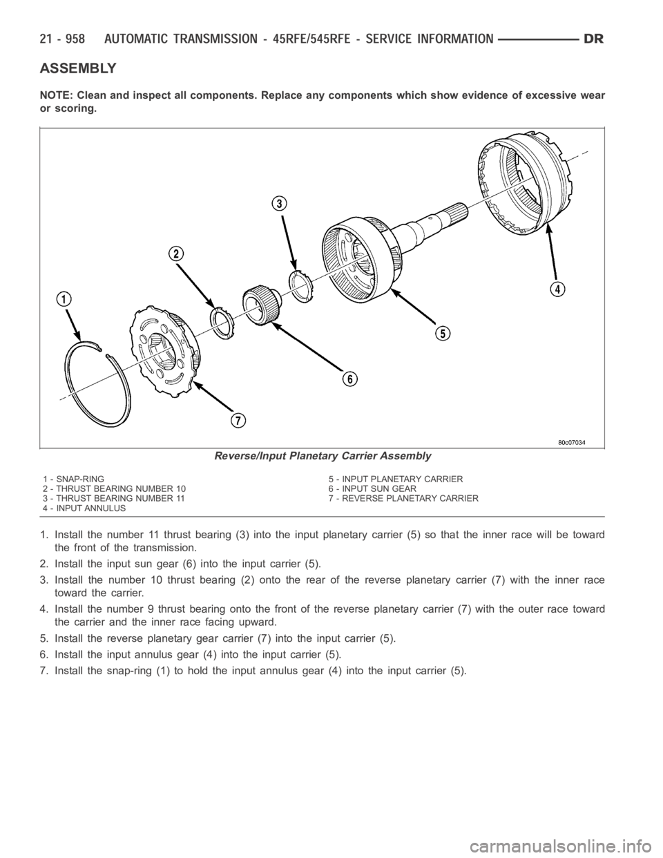
1. Install the number 11 thrust bearing (3) into the input planetary carrier (5) so that the inner race will be toward
the front of the transmission.
2. Install the input sun gear (6) into the input carrier (5).
3. Install the number 10 thrust bearing (2) onto the rear of the reverse planetary carrier (7) with the inner race
toward the carrier.
4. Install the number 9 thrust bearing onto the front of the reverse planetary carrier (7) with the outer race toward
the carrier and the inner race facing upward.
5. Install the reverse planetary gear carrier (7) into the input carrier (5).
6. Install the input annulus gear (4) into the input carrier (5).
7. Install the snap-ring (1) to hold the input annulus gear (4) into the input carrier (5).
Reverse/Input Planetary Carrier Assembly
1 - SNAP-RING 5 - INPUT PLANETARY CARRIER
2 - THRUST BEARING NUMBER 10 6 - INPUT SUN GEAR
3 - THRUST BEARING NUMBER 11 7 - REVERSE PLANETARY CARRIER
4 - INPUT ANNULUS
Page 3480 of 5267
MECHANISM-SHIFT
DESCRIPTION
The gear shift mechanism provides six shift positions which are:
Park (P)
Reverse (R)
Neutral (N)
Drive (D)
Manual second (2)
Manual low (1)
OPERATION
MANUAL LOW (1) range provides first gear only. Overrun braking is also provided in this range. MANUAL SECOND
(2) range provides first and second gear only.
DRIVE range provides FIRST, SECOND, THIRD, OVERDRIVE FOURTH, and OVERDRIVE FIFTH (if applicable)
gear ranges. The shift into OVERDRIVE FOURTH and FIFTH (if applicable) gear ranges occurs only after the trans-
mission has completed the shift into D THIRD gear range. No further movement of the shift mechanism is required
to complete the 3-4 or 4-5 (if applicable) shifts.
The FOURTH and FIFTH (if applicable) gear upshifts occur automatically when the overdrive selector switch is in
the ON position. No upshift to FOURTH or FIFTH (if applicable) gears will occur if any of the following are true:
The transmission fluid temperature is below 10° C (50° F) or above 121° C (250° F).
The shift to THIRD is not yet complete.
Vehicle speed is too low for the 3-4 or 4-5 (if applicable) shifts to occur.
Upshifts into FOURTH or FIFTH (if applicable) will be delayed when the transmission fluid temperature is below 4.5°
C(40°F)orabove115.5°C(240°F).